Aeg-Electrolux 7509D-M/A Benutzerhandbuch
- Kategorie
- Dunstabzugshauben
- Typ
- Benutzerhandbuch

7509D-M/A USER MANUALEN COOKER HOOD 3


FOR PERFECT RESULTS
Thank you for choosing this AEG product. We have created
it to give you impeccable performance for many years, with
innovative technologies that help make life simpler – featu-
res you might not find on ordinary appliances. Please spend
a few minutes reading to get the very best from it.
ACCESSORIES AND CONSUMABLES
In the AEG webshop, you’ll find everything you need to keep
all your AEG appliances looking spotless and working per-
fectly. Along with a wide range of accessories designed and
built to the high quality standards you would expect, from
specialist cookware to cutlery baskets, from bottle holders to
delicate laundry bags…
This appliance is intended to be used in household and similar applications such as:
- Staff kitchen areas in shops, ofces and other working environments
- Farm Houses
- By clients in hotels, motels and other residential type environments
- Bed and breakfast type environments.
Visit the webshop at:
www.aeg-electrolux.com/shop

4
CONTENTS
5
6
8
10
11
Recommendations And Suggestions
Characteristics
Installation
Use
Maintenance
Contents

RECOMMENDATIONS AND SUGGESTIONS
5
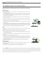
RECOMMENDATIONS AND SUGGESTIONS
The Instructions for Use apply to several versions of this appliance. Accordingly, you
may find descriptions of individual features that do not apply to your specific appli-
ance.
INSTALLATION
• Themanufacturerwillnotbeheldliableforanydamagesresultingfromincorrector
improper installation.
• Theminimumsafetydistancebetweenthecookertopandtheextractorhoodis650mm
(some models can be installed at a lower height, please refer to the paragraphs on work-
ing dimensions and installation).
• Checkthatthemainsvoltagecorrespondstothatindicatedontheratingplatefixedto
the inside of the hood.
• ForClassIappliances,checkthatthedomesticpowersupplyguaranteesadequateearth-
ing.
Connect the extractor to the exhaust flue through a pipe of minimum diameter 120 mm.
The route of the flue must be as short as possible.
• Donotconnecttheextractorhoodtoexhaustductscarryingcombustionfumes(boilers,
fireplaces, etc.).
• Iftheextractorisusedinconjunctionwithnon-electricalappliances(e.g.gasburning
appliances), a sufficient degree of aeration must be guaranteed in the room in order to
prevent the backflow of exhaust gas. The kitchen must have an opening communicating
directly with the open air in order to guarantee the entry of clean air.
USE
• Theextractorhoodhasbeendesignedexclusivelyfordomesticusetoeliminatekitchen
smells.
• Neverusethehoodforpurposesotherthanforwhichithasbendesigned.
• Neverleavehighnakedflamesunderthehoodwhenitisinoperation.
• Adjusttheflameintensitytodirectitontothebottomofthepanonly,makingsurethat
it does not engulf the sides.
• Deepfatfryersmustbecontinuouslymonitoredduringuse:overheatedoilcanburstinto
flames.
• Donotflambèundertherangehood;riskoffire
• Thisapplianceisnotintendedforusebypersons(includingchildren)withreducedphysi-
cal, sensory or mental capabilities, or lack of experience and knowledge, unless they have
been given supervision or instruction concerning use of the appliance by a person re-
sponsible for their safety.
• Childrenshouldbesupervisedtoensurethattheydonotplaywiththeappliance.
MAINTENANCE
• Switchofforunplugtheappliancefromthemainssupplybeforecarryingoutanymain-
tenance work.
• Cleanand/orreplacetheFiltersafterthespecifiedtimeperiod(Firehazard)
• Cleanthehoodusingadampclothandaneutralliquiddetergent.
The symbol on the product or on its packaging indicates that this product may not be treated as household waste. Instead it shall be
handed over to the applicable collection point for the recycling of electrical and electronic equipment. By ensuring this product is disposed
of correctly, you will help prevent potential negative consequences for the environment and human health, which could otherwise be
caused by inappropriate waste handling of this product. For more detailed information about recycling of this product, please contact your
local city office, your household waste disposal service or the shop where you purchased the product.

CHARACTERISTICS
6
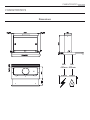
CHARACTERISTICS
Dimensions

CHARACTERISTICS
7
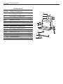
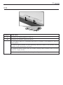
Components
Ref. Q.ty Product Components
1 1 Hood Body, complete with: Controls,
Light, Blower, Filters
8 1 Directional Air Outlet grille
9 1 Reducer Flange ø 150 mm
10a 1 Flange ø 120 mm
10b 1 Adapting ring ø 120-125 mm
20 Closing element
Ref. Q.ty Installation Components
7.1 2 Hood Body Fixing Brackets
12a 8 Screws 3,5 x 16
12e 2 Screws 2,9 x 12,7
12f 5 Screws 2,9 x 9,5
Q.ty Documentation
1 Instruction Manual
12e
8
9
1
12a
20
12f
10a
10b
12a
7.1
12a
7.1

INSTALLATION
8
INSTALLATION
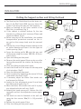
Drilling the Support surface and Fitting the Hood
• TheHoodcanbefitteddirectlyonthelowersur-
face of the Wall Units (650 mm min. above the
Cooker Top) using the snap-on Side Supports.
• Make an opening on the lower surface of the
Wall Unit, as indicated. (fig.1)
• If the cabinet is without bottom, fix the two
brackets at a distance B of minimum 30mm and
maximum 60mm. (fig.2)
• Beforecarryingouttheinstallation,thewooden
transportation protections screwed on the vi-
sor and on the canopy body must be removed.
(fig.3)
• Choosethecorrectflangemeasurebasingonthe
air outlet diameter and insert it to the upper air
outlet opening. (fig.4)
• Screwthe closingprofile20 onto the rear part
of the hood, using the screws 12f (2.9 x 9.5) pro-
vided. (fig.5)
• Opentheslidingsuctionpanel.
• Removethemetalgreasefiltersonebyoneafter
having disconnected the relative fas-tening ele-
ments.
• Closetheslidingsuctionpanelagain.
• InserttheHooduntilthesnap-onsidesup-ports
click into place. (fig.6)
• Opentheslidingsuctionpanel.
• LockinpositionbytighteningthescrewsVffrom
underneath the Hood. (fig.6)
• Ifnecessary, adjust the whole filterholder unit
and proceed as follows:
• LoosenthefouradjustmentscrewsVrandclose
the sliding panel again. (fig.7)
• Movetheentirefilterholderunituntilitisprop-
erly aligned with the wall unit. (fig.8)
• Keepingthehoodcanopystill,removetheslid-
ingpanelandlocktheadjustmentscrewsagain.
(fig.7)
• Thehoodcannowbefastenedtothewallunit
using the four screws 12a (3.5 x 16) provided.
(fig.9)
• Replacethemetalgreasefilters.
• Closetheslidingsuctionpanelagain.
3
DE
1
10
MONTAGE
Bohren der Trägerplatte und Montage der Dunstabzugshaube
• Die Haube kann direkt an der Unterseite der
Hängeschränke (mindestens 650 mm von der
Kochmulde entfernt) mit seitlichen Schnapphal-
terungen fixiert werden.
• An der Unterseite des Hängeschranks, wie in
der Abbildung gezeigt, eine Öffnung anbringen.
(Abb.1)
• Sofern ein Schrank ohne Unterboden benutzt
werden soll, sind die verzinkten Haltewinkel mit
einem Abstand B von 30 bis 60 mm anzubrin-
gen. (Abb.2)
• Vor dem Einbau müssen die als Transportsiche-
rung auf dem Schirm geschraubten Holzleisten
abgenommen werden. (Abb.3)
• Je nach Durchmesser des gewählten Luftaus-
tritts den passenden Flansch in die obere Ab-
luftöffnung einsetzen. (Abb.4)
• Das Abschlussprofil 20 an der Rückseite der
Haube mit den beiliegenden Schrauben 12f
(2,9x9,5) fixieren. (Abb.5)
• Den herausziehbaren Wrasenleitschirm öffnen.
• Die Fettfilter nacheinander entnehmen, indem
die entsprechenden Haltevorrichtungen gelöst
werden.
• Den herausziehbaren Wrasenleitschirm wieder
schließen.
• Die Haube einschieben, bis die seitlichen Halte-
rungen einschnappen. (Abb.6)
• Den herausziehbaren Wrasenleitschirm öffnen.
• Die Haube von unten her mit den Schrauben Vf
fixieren. (Abb.6)
• Falls erforderlichk, das unter Teil wie nachste-
hend beschrieben ausrichten:
• Die vier Einstellschrauben Vr lockern und
den Wrasenleitschirm wieder schließen.
(Abb.7)
• Den gesamten unteren Korpus verschieben,
bis er auf den Oberschrank ausgerichtet ist.
(Abb.8)
• Den Haubenkörper festhalten, den Wrasen-
leitschirms öffnen und die Einstellschrauben
festziehen. (Abb.7)
• Nun kann die Haube am Oberschrank mit den
vier beiliegenden Schrauben 12a (3,5 x 16)
fixiert werden. (Abb.9)
• Die Fettfilter wieder montieren.
• Den herausziehbaren Wrasenleitschirm wieder schließen
1
2
3
4
6
Vr
7
8
9
5
5
6
9
10a
10a
10b
2
4
7
12a
8
9
B

INSTALLATION
9
12e
8
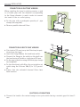
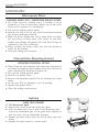
CONNECTION IN DUCTING VERSION
When installing the hood in ducting version, a rigid
or a flexible pipe with the diameter corresponding
to the flange diameter is used in order to connect
the hood to the air outlet piping.
• Fix the pipe with anadequate quantity of pipe
clamps (not supplied).
• Removepossiblecharcoalfilters.
CONNECTION IN RECYCLING VERSION
• Cutaholeø125mminanyshelfthatmaybeposi-
tioned over the hood.
• Inserttheflange10a on the hood body outlet.
• Connecttheflangetotheoutletontheshelfover
the hood using a flexible or rigid pipe ø120 mm.
• Fixthepipeinpositionusingsufficientpipeclamps
(not supplied).
• Fixthedirectionalgrille8 on the recirculation air
outlet using the 2 screws 12e (2,9 x 12,7) provid-
ed.
• Ensure that the activated charcoal filters have
been inserted.
ELECTRICAL CONNECTION
• Connectthehoodtothemainsthroughatwo-poleswitchhavingacontactgapofatleast3
mm.

USE
10
USE
SWITCH FUNCTIONS
L Switches the lighting system on and off
M Switches the extractor motor on and off
1. Low speed, used for a continuous and silent air change in the presence of light co-
oking vapour..
2. Medium speed, suitable for most operating conditions, thanks to an optimum relation
between hood performance and noise.
3. Maximum speed, suitable when the highest cooking vapour emission has to be elimi-
nated for longer periods.
i. Intensive speed, suitable for the strongest cooking vapours and odours.
L
M

MAINTENANCE
11
MAINTENANCE
Metal grease filters
CLEANING METAL SELF- SUPPORTING GREASE FILTERS
• The filters must be cleaned every 2 months, or more
frequently in case of particularly heavy use of the hood.
Filters can be washed in a dishwasher.
• Pullout the sliding suction panel.
• Remove thefilters onebyone, after having disconnected
the relative fastening elements.
• Washthe filters, taking care not to bend them. Let them
get dry before refitting them. (The colour of the filter
surface may change throughout the time but this has no
influence to the filter efficiency).
• When refitting the filters, make sure that the handle is
visible on the outside.
• Closethe sliding suction panel.
Charcoal Filter (Recycling Version)
REPLACING CHARCOAL FILTERS
• Thesefiltersarenotwashableandcannotberegenerated,
and must be replaced approximately every four months or
more frequently by particularly heavy use.
• Pullout the sliding suction panel.
• Removethe greasefilters.
• Removethesaturatedcarbonfilterbyreleasingthefixing
hooks
• Fitthe new filter by hookingit into its seating.
• Replacethe greasefilters.
• Closethe sliding suction panel.
Lighting
LIGHT REPLACEMENT
11 W fluorescent light
• Remove themetal terminals fixing the glass.
• Slide theglass cover out of oneof the fastening clips.
Lower the unfastened part of the glass cover slightly, so
that the cover can be completely removed.
• Replace thelight with a new oneof the same type and
rating.
• Replace theglass cover in reverse order.

www.aeg-electrolux.com/shop
436005589_01 - 111010
-
 1
1
-
 2
2
-
 3
3
-
 4
4
-
 5
5
-
 6
6
-
 7
7
-
 8
8
-
 9
9
-
 10
10
-
 11
11
-
 12
12


Aeg-Electrolux 7509D-M/A Benutzerhandbuch
- Kategorie
- Dunstabzugshauben
- Typ
- Benutzerhandbuch
in anderen Sprachen
- English: Aeg-Electrolux 7509D-M/A User manual