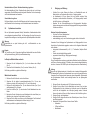
WALTHER PILOT PILOT WA 51 Bedienungsanleitung
- Kategorie
- Power-Feinsprühsysteme
- Typ
- Bedienungsanleitung
Dieses Handbuch eignet sich auch für

Betriebsanleitung / Operating Instruction
PILOT WA 51
Automatik-Spritzpistole / Automatic Spray Gun

Seite 8 - 20
Page 22 - 34

4 5
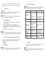
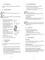
2.1
2.2
Spritzluftanschluss PK 4
Kennzeichung: SP
Atomizing air inlet fitting PK4
Identification: SP
Spritzluftanschluss PK 4
Kennzeichung: SP
Atomizing air inlet fitting PK 4
Identification: SP
Steuerluftanschluss PK 3
Kennzeichnung: ST
Control air connection PK 3
Identification: ST
13
WA 51
Stand: Januar 2011
Materialanschluss PK 4
Kennzeichnung: M
Material conncetion PK 4
Identification: M

6 7
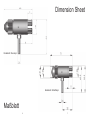
Maßblatt
Dimension Sheet
Rundstrahl / Round jet
Breitstrahl / Wide/flat jet

8 9
EG/EU-Konformitätserklärung
Wir, der Gerätehersteller, erklären in alleiniger Verantwortung, dass das Produkt in der
untenstehenden Beschreibung den einschlägigen grundlegenden Sicherheits- und
Gesundheitsanforderungen entspricht. Bei einer nicht mit uns abgestimmten Änderung
an dem Gerät oder bei einer unsachgemäßen Verwendung verliert diese Erklärung ihre
Gültigkeit.
Hersteller WALTHER Spritz- und Lackiersysteme GmbH
Kärntner Str. 18 - 30
D - 42327 Wuppertal
Tel.: +49(0)202 / 787 - 0
Fax: +49(0)202 / 787 - 2217
www.walther-pilot.de • e-mail: [email protected]
Typenbezeichnung Automatische Spritzpistolen PILOT WA 51
Rundstrahl V 20 306 51
Breitstrahl V 20 306 01
Verwendungszweck Verarbeitung spritzbarer Materialien
Angewandte Normen und Richtlinien
EG-Maschinenrichtlinien 2006/42/EG
2014/34/EU (ATEX Richtlinien)
DIN EN ISO 12100
DIN EN 1953 DIN EN 13463-1
DIN EN 1127-1 DIN EN 13463-5
Spezifikation im Sinne der Richtlinie 2014/34/EU
Kategorie 2 Gerätebezeichnung II 2 G c T 5
Tech.File,Ref.:
2406
Bevollmächtigt mit der Zusammenstellung der technischen Unterlagen:
Nico Kowalski, WALTHER Spritz- und Lackiersysteme GmbH, Kärntner Str. 18 - 30
D- 42327 Wuppertal
Besondere Hinweise :
Das Produkt ist zum Einbau in ein anderes Gerät bestimmt. Die Inbetriebnahme ist
so lange untersagt, bis die Konformität des Endproduktes mit der Richtlinie
2006/42/EG festgestellt ist.
Wuppertal, den 27. April 2017
Name: Torsten Bröker
Stellung im Betrieb: Leiter der Konstruktion und Entwicklung
Diese Erklärung ist keine Zusicherung von Eigenschaften im Sinne der Produkthaftung. Die Sicherheitshinweise
der Produktdokumentation sind zu beachten.
Inhaltsverzeichnis
Explosionszeichnung 4
Maßblatt 6
EG-Konformitätserklärung 9
Ersatzteilliste 10
1 Allgemeines 11
1.1 Kennzeichnung des Modells 11
1.2 Bestimmungsgemäße Verwendung 11
1.3 Sachwidrige Verwendung 12
2 Technische Beschreibung 12
3 Sicherheitshinweise 12
3.1 Kennzeichnung der Sicherheitshinweise 12
3.2 Allgemeine Sicherheitshinweise 13
4 Montage 14
4.1 Spritzpistole befestigen 14
4.2 Versorgungsleitungen anschließen 14
5 Bedienung 14
5.1 Sicherheitshinweise 14
5.2 Inbetrieb- und Außerbetriebsetzen 15
5.3 Spritzbildprobe erzeugen 15
5.4 Spritzbild verändern 15
5.5 Spritzautomat umrüsten 16
6 Reinigung und Wartung 17
7 Instandsetzung 18
7.1 Nadeldichtung wechseln 18
7.2 Materialdüse, -nadel, Federn und Dichtungen austauschen 18
8 Fehlersuche und -beseitigung 19
9 Entsorgung 19
10 Technische Daten 20
ppa.

10 11
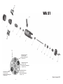
Ersatzteilliste PILOT WA 51
PILOT WA 51
V 20 306
Pos. Bezeichnung Stck Artikelnummer
1 Luftkopfmutter 1 V 20 335 15 000
2 Rundstrahlluftkopf 1 V 20 336 34 . . 5*
2.1 kleiner Breitstrahlluftkopf 1 V 20 336 44 . . 2*
2.2 großer Breitstrahlluftkopf 1 V 20 336 50 . . 5*
3 Materialdüse 1 V 20 336 23 . . 3*
4 Packungsschraube 1 V 20 305 04 003
5 Nadeldichtung 1 V 20 305 13 000
6 Gehäuse kompl. 1 V 20 306 01 003
7 Nutring 1 V 09 220 26 000
8 Materialnadel 1 V 20 306 06 . . 3*
9 O - Ring 1 V 09 102 21 001
10 Kolben 1 V 20 305 03 004
11 Sechskantmutter 1 V 20 305 07 003
12 Kolbenfeder 1 V 20 305 12 005
13 Federbuchse 1 V 20 305 02 003
14 Innensechskantschraube 2 V 20 305 08 003
15 Befestigungsbolzen 1 V 20 305 14 003
* Bei Ersatzteillieferung bitte entsprechende Größe angeben. Wir empfehlen, alle
fettgedruckten Ersatzteile (Verschleißteile) auf Lager zu halten.
Düseneinlage:
Die Düseneinlage besteht aus Luftkopf,
Materialdüse und Materialnadel.
Artikelnummer
V 15 306 02 . . 3
Düsenausstattung nach Wahl:
0,3 • 0,5 • 0,8 • 1,0 • 1,2 • 1,5 mm ø
1 Allgemeines
1.1 Kennzeichnung des Modells
Modell: Automatische Spritzpistole PILOT WA 51
Typ: V 20 306 51 (Rundstrahl)
V 20 306 01 (Breitstrahl)
Hersteller: WALTHER Spritz-und Lackiersysteme GmbH
Kärntner Str. 18-30
D-42327 Wuppertal
Tel.: 0202 / 787-0
Fax: 0202 / 787-2217
www.walther-pilot.de • Email: [email protected]
1.2 Bestimmungsgemäße Verwendung
Die automatische Spritzpistole PILOT WA 51 dient ausschließlich der Verarbeitung
spritzbarer Medien, insbesondere :
• Lacke und Farben
• Fette, Öle und Korrosionsschutzmittel
• Kleber
• Keramikglasuren
• Beizen
Sind Materialien, die Sie verspritzen wollen hier nicht aufgeführt, wenden Sie sich
bitte an WALTHER Spritz- und Lackiersysteme GmbH, Wuppertal.
Sämtliche materialführenden Teile sind aus Edelstahl rostfrei gefertigt.
Die spritzbaren Materialien dürfen lediglich auf Werkstücke bzw. Gegenstände
aufgetragen werden.
Die Temperatur des Spritzmaterials darf 80° C nicht überschreiten.
Das Modell PILOT WA 51 ist kein handgeführter Spritzautomat und muss deshalb an
einer geeigneten Halterung befestigt werden.
Die bestimmungsgemäße Verwendung schließt auch ein, dass alle Hinweise und
Angaben der vorliegenden Betriebsanleitung gelesen, verstanden und beachtet
werden.
Das Gerät erfüllt die Explosionsschutz-Forderungen der Richtlinie 2014/34/EU
(ATEX) für die auf dem Typenschild angegebene Explosionsgruppe, Gerätekategorie,
und Temperaturklasse. Beim Betreiben des Gerätes sind die Vorgaben dieser
Betriebsanleitung unbedingt einzuhalten. Die vorgeschriebenen Inspektions- und
Wartungsintervalle sind einzuhalten.
Die Angaben auf den Geräteschildern bzw. die Angaben in dem Kapitel technische
Daten sind unbedingt einzuhalten und dürfen nicht überschritten werden. Eine
Überlastung des Gerätes muss ausgeschlossen sein. Das Gerät darf in explosions-
gefährdeten Bereichen nur nach Maßgabe der zuständigen Aufsichtsbehörde
eingesetzt werden.

12 13
Der zuständigen Aufsichtsbehörde bzw. dem Betreiber obliegt die Festlegung
der Explosionsgefährdung (Zoneneinteilung).
Es ist betreiberseitig zu prüfen und sicherzustellen, dass alle technischen Daten und
die Kennzeichnung gemäß ATEX mit den notwendigen Vorgaben übereinstimmen.
Bei Anwendungen, bei denen der Ausfall des Gerätes zu einer Personengefährdung
führen könnten, sind betreiberseitig entsprechende Sicherheitsmaßnahmen
vorzusehen.
Falls im Betrieb Auffälligkeiten erkannt werden, muss das Gerät sofort stillgesetzt
werden und es ist mit WALTHER-Spritz-und Lackiersysteme Rücksprache zu halten.
Erdung / Potentialausgleich
Es muss sichergestellt werden, dass die Spritzpistole separat oder in Verbindung mit
dem Gerät auf dem sie aufgebaut ist, ausreichend geerdet ist (maximaler Widerstand
10
6
Ω).
1.3 Sachwidrige Verwendung
Der Spritzautomat darf nicht anders verwendet werden, als es im Abschnitt Bestim-
mungsgemäße Verwendung geschrieben steht. Jede andere Verwendung ist sach-
widrig. Zur sachwidrigen Verwendung gehören z.B.:
• das Verspritzen von Materialien auf Personen und Tiere
• das Verspritzen von flüssigem Stickstoff.
2 Technische Beschreibung
Das Modell PILOT WA 51 arbeitet automatisch über eine Druckluftsteuerung und wird
über 3/2-Wege-Steuerventile angesteuert. Dazu können Hand-, Fuß- oder
Magnetventile eingesetzt werden.
Zunächst wird die Zerstäuberluft über ein 3/2- Wege-Ventil zugeschaltet.
Danach wird das für die Steuerluft erforderliche 3/2-Wege-Steuerventil angesteuert.
Die in den Zylinderraum einströmende Druckluft betätigt den Steuerkolben und öffnet
die Materialzufuhr.
Wird die Steuerluft durch das 3/2-Wege-Ventil unterbrochen, entweicht die im
Zylinderraum befindliche Druckluft. Der Federdruck der Kolbenfeder verschließt die
Materialzufuhr zur Materialdüse.
Anschließend wird die Zerstäuberluft über das 3/2-Wege-Ventil abgeschaltet.
3 Sicherheitshinweise
3.1 Kennzeichnung der Sicherheitshinweise
Warnung
Das Piktogramm und die Dringlichkeitsstufe „Warnung“ kennzeichnen eine
mögliche Gefahr für Personen.
Mögliche Folgen: schwere oder leichte Verletzungen.
Achtung
Das Piktogramm und die Dringlichkeitsstufe „Achtung“ kennzeichnen eine
mögliche Gefahr für Sachwerte. Mögliche Folgen: Beschädigung von Sachen.
Hinweis
Das Piktogramm und die Dringlichkeitsstufe „Hinweis“ kennzeichnen zusätzliche
Informationen für das sichere und effiziente Arbeiten mit dem Spritzautomaten.
3.2 Allgemeine Sicherheitshinweise
• Die einschlägigen Unfallverhütungsvorschriften sowie die sonstigen anerkannten
sicherheitstechnischen und arbeitsmedizinischen Regeln sind einzuhalten.
• Benutzen Sie den Spritzautomaten nur in gut belüfteten Räumen. Im Arbeits-
bereich ist Feuer, offenes Licht und Rauchen verboten. Beim Verspritzen leichtent-
zündlicher Materialien (z. B. Lacke, Kleber, Reinigungsmittel usw.) besteht erhöhte
Gesundheits-, Explosions- und Brandgefahr.
• Es muss sichergestellt werden, dass der Spritzautomat separat oder in Verbindung
mit dem Gerät auf dem sie aufgebaut ist, ausreichend geerdet ist (maximaler
Widerstand 10
6
Ω).
• Schalten Sie vor jeder Wartung und Instandsetzung die Luft- und Materialzufuhr
zum Spritzautomaten drucklos - Verletzungsgefahr.
• Halten Sie beim Verspritzen von Materialien keine Hände oder andere Körperteile
vor die unter Druck stehende Düse des Spritzautomaten - Verletzungsgefahr.
• Richten Sie den Spritzautomaten nicht auf Personen und Tiere - Verletzungsgefahr.
• Beachten Sie die Verarbeitungs- und Sicherheitshinweise der Hersteller von
Spritzmaterial und Reinigungsmittel. Insbesondere aggressive und ätzende
Materialien können gesundheitliche Schäden verursachen.
• Die partikelführende Abluft ist vom Arbeitsbereich und Betriebspersonal fernzuhal-
ten. Tragen Sie dennoch vorschriftsgemäßen Atemschutz und vorschriftsgemäße
Arbeitskleidung, wenn Sie mit dem Spritzautomaten Materialien verarbeiten.
• Umherschwebende Partikel gefährden Ihre Gesundheit.
• Tragen Sie im Arbeitsbereich des Spritzautomaten einen Gehörschutz. Der
erzeugte Schallpegel des Spritzautomaten beträgt ca. 83 dB (A).
• Achten Sie stets darauf, dass bei Inbetriebnahme, insbesondere nach Montage-
und Wartungsarbeiten alle Muttern und Schrauben fest angezogen sind.
• Verwenden Sie nur Original-Ersatzteile, da WALTHER nur für diese eine sichere
und einwandfreie Funktion garantieren kann.
• Bei Nachfragen zur gefahrlosen Benutzung des Spritzautomaten sowie der darin
verwendeten Materialien, wenden Sie sich bitte an WALTHER Spritz- und
Lackiersysteme GmbH, D-42327 Wuppertal.

14 15
4 Montage
Die automatische Spritzpistole ist werkseitig komplett montiert. Bevor Sie die Spritz-
pistole in Betrieb setzen können, sind die folgenden Tätigkeiten durchzuführen:
4.1 Spritzpistole befestigen
Befestigen Sie den Spritzautomaten an einer geeigneten, standsicheren Halterung,
Durchmesser 6,0 mm.
4.2 Versorgungsleitungen anschließen
Warnung
Achten Sie darauf, dass die Anschlüsse nicht vertauscht werden
- Verletzungsgefahr.
Warnung
Material- und Luftschläuche, die mit einer Schlauchtülle befestigt werden, müssen
zusätzlich mit einer Schlauchschelle gesichert sein.
Der Spritzautomat ist nun vollständig montiert und kann in Betrieb gesetzt werden.
5 Bedienung
5.1 Sicherheitshinweise
Beachten Sie bei der Bedienung der Spritzpistole insbesondere die nachfolgenden
Sicherheitshinweise!
• Tragen Sie vorschriftsmäßigen Atemschutz und Arbeitskleidung, wenn Sie mit
der Spritzpistole Materialien verspritzen. Umherschwebende Partikel gefährden
Ihre Gesundheit.
• Tragen Sie im Arbeitsbereich des Spritzautomaten einen Gehörschutz. Der
Materialanschluss
PK 4
Kennzeichnung: M
Spritzluftanschluss
PK 4
Kennzeichung: SP
Spritzluftanschluss
PK 4
Kennzeichung: SP
Steuerluftanschluss
PK 3
Kennzeichnung: ST
• Befestigen Sie den Steuerluftanschuss (über
das 3/2-Wege-Ventil) an dem Spritzautomaten
"ST" und stellen den erforderlichen Steuerluft-
druck ein (min. 4,5 bar).
• Befestigen Sie den Zerstäuberluftanschluss an
der Luftleitung (gereinigte Druckluft) und an den
Zerstäuberluftanschlüssen "SP".
• Schalten Sie die Druckluft ein und stellen am
Reduzierventil den gewünschten Zerstäuberluft-
druck ein (max. 6 bar).
• Füllen Sie Material in das Materialdruckgefäß
ein und verschließen den Deckel.
• Befestigen Sie den Materialzuführungsschlauch
am Materialdruckgefäß bzw. einer Pumpenanla-
ge und am Materialanschluss "M". Stellen Sie
den gewünschten Materialdruck (max. 6 bar)
ein.
• Öffnen Sie den Materialhahn am Druckgefäß.
erzeugte Schallpegel des Spritzautomaten von ca. 83 dB (A) kann einen
Gehörschaden verursachen.
• Im Arbeitsbereich ist Feuer, offenes Licht und Rauchen verboten. Beim
Verspritzen leicht entzündbarer Materialien (z. B. Lacke, Kleber) besteht
erhöhte Explosions- und Brandgefahr.
5.2 Inbetrieb- und Außerbetriebsetzen
Bevor Sie die automatische Spritzpistole in Betrieb setzen können, müssen folgende
Voraussetzungen erfüllt sein:
• Der Steuerluftdruck muss an dem Spritzautomaten anstehen.
• Der Zerstäuberluftdruck (Rund- und Breitstrahl) muss an dem Spritz-automaten
anstehen.
• Der Materialdruck muss an dem Spritzautomaten anstehen.
Achtung
Der Materialdruck darf nicht höher eingestellt sein als • 6 bar, da sonst kein funkti-
onssicherer Betrieb des Spritzautomaten gewährleistet ist.
Stellen Sie den Steuerluftdruck auf • mindestens 4,5 bar, damit der Spritzautomat in
Betrieb gesetzt werden kann.
Sie können den Spritzautomaten in und außer Betrieb setzen, indem Sie das
3/2-Wege-Steuerventil betätigen (siehe Betriebsanleitung des Anlagenherstellers).
Warnung
Der Spritzautomat muss nach Arbeitsende immer drucklos geschaltet werden. Die
unter Druck stehenden Leitungen können platzen und nahestehende Personen
durch das ausströmende Material verletzen.
5.3 Spritzbildprobe erzeugen
Eine Spritzbildprobe sollte immer dann erzeugt werden, wenn:
• der Spritzautomat zum erstenmal in Betrieb gesetzt wird
• das Spritzmaterial ausgetauscht wird
• der Automat zur Wartung oder Instandsetzung zerlegt wurde.
Die Spritzbildprobe kann auf ein Probewerkstück, Blech, Pappe oder Papier
abgegeben werden.
5.4 Spritzbild verändern
Materialdurchflussmenge einstellen (Nadelhubbegrenzung)
Die Bestimmung der Materialdurchflussmenge ist anhand der Auswahl einer geeig-
neten Düsengröße vorzunehmen. Sie ist außerdem abhängig vom anstehenden
Materialdruck.
Materialdruck regulieren
Diese Einstellung nehmen Sie an der Pumpe oder am Druckbehälter vor. Beachten
Sie dabei die Anweisungen und Sicherheitshinweise des Herstellers.

16 17
Zerstäuberluftdruck (Rund- / Breitstrahleinstellung) regulieren
Der Zerstäuberluftdruck (Rund- / Breitstrahl) wird stufenlos über ein in der Anlage
angeordnetes Druckluft-Reduzierventile eingestellt. Beachten Sie die Anweisungen
und Sicherheitshinweise des Herstellers.
Steuerluftdruck regulieren
Der Steuerluftdruck wird am Druckluft-Reduzierventil der Kompressoranlage einge-
stellt. Beachten Sie die Anweisungen und Sicherheitshinweise des Herstellers.
5.5 Spritzautomat umrüsten
Die zum Spritzmaterial passende Luftkopf-, Materialdüse-, Nadelkombination bildet
eine aufeinander abgestimmte Einheit - die Düseneinlage. Tauschen Sie immer die
komplette Düseneinlage aus, damit die gewünschte Spritzbildqualität erhalten bleibt.
Warnung
Unterbrechen sie vor jeder Umrüstung die Luft- und Materialzufuhr zu dem
Spritzautomaten.
Hinweis
Zur Durchführung der im Folgenden aufgeführten Arbeitsschritte benutzen Sie bitte
die Explosionszeichnung (Seite 4) dieser Betriebsanleitung.
Luftkopf und Materialdüse wechseln
1. Schrauben Sie die Luftkopfmutter (Pos. 1) ab und entfernen den Luftkopf
(Pos. 2).
2. Schrauben Sie die Materialdüse (Pos. 3) aus dem Gehäuse (Pos. 6).
Der Einbau geschieht in umgekehrter Reihenfolge.
Materialnadel wechseln
1. Entfernen Sie alle Schläuche von den Anschlüssen.
2. Schrauben Sie die beiden Innensechskantschrauben (Pos. 14) aus dem
Gehäuse und ziehen Sie Federbuchse (Pos. 13) nach hinten heraus .
3. Entfernen Sie die Kolbenfeder (Pos. 12) und ziehen den Kolben (Pos. 10) mit
der Materialnadel (Pos. 8) heraus.
4. Lösen Sie die Mutter (Pos. 11) und schrauben Sie die Materialnadel aus dem
Kolben.
5. Bestreichen Sie das Gewinde der neuen Materialnadel mit einem Kleber (zum
Abdichten) und schrauben Sie die Nadel in den Kolben.
6. Schrauben Sie die Mutter zum Kontern auf die Materialnadel. Das Einstellmaß
der Materialnadel von Nadelspitze bis Kolben beträgt 41,5 mm.
Der Einbau geschieht in umgekehrter Reihenfolge.
6 Reinigung und Wartung
• Schalten Sie vor jeder Wartung die Steuer- und Zerstäuberluft sowie die
Materialzufuhr zum Spritzautomaten drucklos - Verletzungsgefahr.
• Im Arbeitsbereich ist Feuer, offenes Licht und Rauchen verboten. Beim
Verspritzen leichtentzündlicher Materialien (z.B. Reinigungsmittel) besteht
erhöhte Explosions- und Brandgefahr.
• Beachten Sie die Sicherheitshinweise des Reinigungsmittel Herstellers.
Insbesondere aggressive und ätzende Reinigungsmittel können gesundheitliche
Schäden verursachen.
Reinigen Sie den Spritzautomaten
• vor jedem Farb- bzw. Materialwechsel
• mindestens einmal wöchentlich
• materialabhängig und je nach Verschmutzungsgrad mehrfach wöchentlich.
Verwenden Sie zur Reinigung des Spritzautomaten nur Reinigungsmittel, die vom
Hersteller des Spritzmaterials angegeben werden und die folgenden Bestandteile
nicht enthalten:
• halogenierte Kohlenwasserstoffe (z. B. 1,1,1, Trichlorethan, Methylen-Chlorid
usw.)
• Säuren und säurehaltige Reinigungsmittel
• regenerierte Lösemittel (sog. Reinigungsverdünnungen)
• Entlackungsmittel.
Die o.g. Bestandteile verursachen an galvanisierten Bauteilen chemische Reaktionen
und führen zu Korrosionsschäden. Für Schäden, die aus einer derartigen Behandlung
herrühren, übernimmt WALTHER Spritz-und Lackiersysteme keine Gewährleistung.
Achtung
Legen Sie den Spritzautomaten nie in Lösemittel oder ein anderes Reinigungsmittel.
Die einwandfreie Funktion des Spritzautomaten kann sonst nicht garantiert werden.
Verwenden Sie zur Reinigung keine harten oder spitzen Gegenstände. Präzisionsteile
des Spritzautomaten könnten sonst beschädigt werden und das Spritzergebnis
verschlechtern.
1. Zerlegen Sie den Automaten gemäß 5.5 Spritzautomat umrüsten.
2. Reinigen Sie den Luftkopf und die Materialdüse mit einem Pinsel und dem
Reinigungsmittel.Vor dem Aufsetzen des Luftkopfes muss die Materialdüse
außen und die Auflagefläche des Luftkopfes gereinigt werden. Farbreste
können sich zwischen Düse und Luftkopf setzen und die Luftzuführung stören.
3. Reinigen Sie ggf. den Materialkanal.
4. Reinigen Sie alle übrigen Bauteile und den Pistolenkörper mit einem Tuch und
dem Reinigungsmittel.
5. Bestreichen Sie folgende Teile mit einem dünnen Fettfilm:
• Kolbenfeder
• O-Ring des Kolbens
• Materialnadel

18 19
Verwenden Sie dazu ein säurefreies, nicht harzendes Fett und einen Pinsel.
Anschließend wird der Spritzautomat in umgekehrter Reihenfolge zusammenge-
setzt.
7 Instandsetzung
Warnung
Schalten Sie vor jeder Instandsetzung die Steuer- und Zerstäuberluft sowie die
Materialzufuhr zum Spritzautomaten drucklos - Verletzungsgefahr.
Hinweis
Zur Durchführung der im Folgenden aufgeführten Arbeitsschritte benutzen Sie bitte
die Zeichnung (Seite 4) dieser Betriebsanleitung.
7.1 Nadeldichtung wechseln
1. Bauen Sie Luftkopf, Materialdüse und Materialnadel, wie unter 5.5 Spritzautomat
umrüsten beschrieben, aus.
2. Schrauben Sie die Packungsschraube (Pos. 4) aus dem Gehäuse.
3. Ziehen Sie die Nadeldichtung (Pos. 5) mit einem Hilfswerkzeug aus ihrem Sitz.
Verwenden Sie hierzu einen festen Draht, dessen Ende zu einem kleinen Haken
umgebogen ist.
Der Einbau geschieht in umgekehrter Reihenfolge.
Hinweis
Die aus dem Pistolenvorsatz entnommene Nadeldichtung (Pos. 5) darf nicht wieder
verwendet werden, da sonst eine funktionssichere Dichtwirkung nicht gewährleistet
ist.
7.2 Materialdüse, -nadel, Federn und Dichtungen austauschen
Zerlegen Sie den Spritzautomaten gemäß Abschnitt 5.5 Materialdüse und -nadel
wechseln, wenn die folgenden Bauteile ausgetauscht werden müssen:
• Materialdüse
• Materialnadel*
• Kolbenfeder*
• O-Ring des Kolbens*
Hinweis
Die mit * gekennzeichneten Bauteile müssen vor dem Einbau in das Pistolenge-
häuse mit einem säurefreien, nicht harzenden Fett eingefettet werden.
8 Fehlersuche und -beseitigung
Warnung
Schalten Sie vor jeder Wartung und Instandsetzung die Steuer- und Zerstäuberluft
sowie Materialzufuhr zum Spritzautomaten drucklos - Verletzungsgefahr.
Fehler Ursache Abhilfe
Pistole tropft
Materialnadel (Pos. 8)
oder -düse (Pos. 3) ver-
schmutzt
Materialnadel oder -düse
beschädigt
siehe 5.5 Materialnadel oder
-düse ausbauen und reinigen
siehe 5.5 Materialnadel oder
-düse austauschen
Pistole öffnet nicht Steuerluft zu niedrig
Steuerluftdruck erhöhen
auf min. 4,5 bar
Material sprudelt im
Materialbehälter
Zerstäuberluft gelangt
über Materialkanal in den
Materialbehälter.
Materialdüse (Pos. 3) oder
Luftkopf (Pos. 2) nicht
richtig angezogen
Teile reinigen, anziehen oder
ersetzen
Stoßweiser oder
flatternder
Spritzstahl
zu wenig Material im
Materialbehälter
Material auffüllen (siehe
Betriebsanleitung des
Anlagenherstellers)
Spritzstrahl einseitig
Hornbohrung am Luftkopf
verschmutzt
ausbauen und reinigen
Material tritt aus der
Leckagebohrung
Nadeldichtung (Pos. 5)
undicht
austauschen
9 Entsorgung
Die bei der Reinigung und Wartung anfallenden Materialien sind den Gesetzen und
Vorschriften entsprechend sach- und fachgerecht zu entsorgen.
Warnung
Beachten Sie insbesondere die Hinweise des Herstellers der Spritz- und
Reinigungsmittel. Unachtsam entsorgtes Material gefährdet die Gesundheit von
Mensch und Tier.

20
10 Technische Daten
Gewicht: 94 g
Anschluss:
Breitstrahlluft PK 4
Rundstrahlluft PK 4
Steuerluft PK 3
Materialzufuhr PK 4
Druckbereiche:
Steuerluft mind. 4,5 bar
Materialdruck max. 6 bar
Zerstäuberluft max. 6 bar
max. Betriebstemperatur
der Spritzpistole 80 °C
Schallpegel
(gemessen in ca. 1 m
Abstand zur Spritzpistole) 83 dB (A)
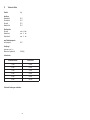
Luftverbrauch:
Zerstäuberluftdruck Luftverbrauch
1,0 bar 50 l/min
2,0 bar 60 l/min
3,0 bar 70 l/min
4,0 bar 85 l/min
5,0 bar 90 l/min
6,0 bar 100 l/min
Technische Änderungen vorbehalten.

22 23
Contents
Exploded Drawing 4
Dimension Sheet 6
Declaration of CE-Conformity 23
List of Replacement Parts 24
1 General 25
1.1 Identification of Model Versions 25
1.2 Normal Use 25
1.3 Improper Use 26
2 Technical Description 26
3 Safety instructions 26
3.1 Identification of safety instructions 26
3.2 General Safety Instructions 27
4 Assembly 27
4.1 Mounting of the Spray Gun 28
4.2 Connection of Input Lines 28
5 Operational Handling 28
5.1 Safety Warnings 28
5.2 Starting / Stopping Requirements 29
5.3 Spray Pattern Test 29
5.4 Spray Pattern Adjustments 29
5.5 Retooling of Spray Gun 30
6 Cleaning and Maintenance 31
7 Repairs 32
7.1 Changing the Needle Seal 32
7.2 Replacement of Nozzles, Needles, Springs and Seals 32
8 Troubleshooting and Corrective Action 33
9 Disposal of Cleaning and Servicing 33
Substances
10 Technical Data 34
Declaration of EC/EU-Conformity
We, the manufacturers of the equipment, hereby declare under our sole responsibility
that the product(s) described below conform to the essential safety requirements. This
declaration will be rendered invalid if any changes are made to the equipment without
prior consultation with us.
Manufacturer WALTHER Spritz- und Lackiersysteme GmbH
Kärntner Str. 18 - 30
D - 42327 Wuppertal
Tel.: +49(0)202 / 787 - 0
Fax: +49(0)202 / 787 - 2217
www.walther-pilot.de • e-mail: [email protected]
Type Designation Automatic spray gun PILOT WA 51
round jet V 20 306 51
wide/flat jet V 20 306 01
Intended purpose Processing of sprayable media
Applied Standards and Directives
EU-Mechanical Engineering Directives 2006/42/EC
2014/34/EU (ATEX Directives)
DIN EN ISO 12100
DIN EN 1953 DIN EN 13463-1
DIN EN 1127-1 DIN EN 13463-5
Specification according 2014/34/EU
Category 2 Part marking II 2 G c T 5
Tech.File,Ref.:
2406
Authorized with the compilation of the technical file:
Nico Kowalski, WALTHER Spritz- und Lackiersysteme GmbH, Kärntner Str. 18 - 30
D- 42327 Wuppertal
Special remarks :
The named product is intended for installation in other equipment. Commissioning is
prohibited until such time as the end product has been proved to conform to the
provision of the Directives 2006/42/EC.
Wuppertal, the 27th of April 2017
Name: Torsten Bröker
Position: Manager, Design and Development
This Declaration does not give assurance of properties in the sense of product liability. The safety instructions
provided in the product documentation must be observed at all times.
p.p.

24 25
List of replacement parts PILOT WA 51
PILOT WA 51
V 20 306
Item Description
Qty.
Art.-No.
1 Air cap nut 1 V 20 335 15 000
2 Round fan cap 1 V 20 336 34 . . 5*
2.1 Wide fan cap, small 1 V 20 336 44 . . 2*
2.2 Wide fan cap, large 1 V 20 336 50 . . 5*
3 Material nozzle 1 V 20 336 23 . . 3*
4 Packing screw 1 V 20 305 04 003
5 Needle seal 1 V 20 305 13 000
6 Housing, complete 1 V 20 306 01 003
7 Lip seal 1 V 09 220 26 000
8 Material needle 1 V 20 306 06 . . 3*
9 O-ring 1 V 09 102 21 001
10 Piston 1 V 20 305 03 004
11 Hexagonal nut 1 V 20 305 07 003
12 Piston spring 1 V 20 305 12 005
13 Spring bushing 1 V 20 305 02 003
14 Hexagonal socket screw 2 V 20 305 08 003
15 Fastening bolt 1 V 20 305 14 003
* Please indicate the required sizes when placing an order for replacement parts.
We recommend that bold-face replacement parts (i.e. wear parts) are hold on stock.
Nozzle Set:
The nozzle insert consists of air cap, material
nozzle and material needle.
Art.-No.
V 15 306 02 . . 3
Nozzle sizes optional:
0,3 • 0,5 • 0,8 • 1,0 • 1,2 • 1,5 mm ø
1 General
1.1 Identification of Model Versions
Models: Automatic Spray Guns PILOT WA 51
Type: V 20 305 51 (round jet)
V 20 305 01 (wide/flat jet)
Manufacturer: WALTHER Spritz-und Lackiersysteme GmbH
Kärntner Str. 18-30
D-42327 Wuppertal
Tel.: 00 49 202 / 787-0
Fax: 00 49 202 / 787-2217
www.walther-pilot.de • Email: [email protected]
1.2 Normal Use
The automatic spray gun PILOT WA 51 must be used only for processing sprayable
materials, in particular :
• lacquers and paints
• grease, oil and anti-corrosion agents
• adhesives
• ceramic glazes
• stains
If you intend to spray materials that are not listed here, please contact WALTHER
Spritz- und Lackiersysteme GmbH, Wuppertal.
All parts which are in contact with the material are made of corrosion-free stainless
steel.
The sprayable materials must be sprayed only on workpieces or objects.
The temperature of the material to be sprayed must not exceed 80°C.
The model PILOT WA 51 is not a hand-held spray gun and must therefore be
mounted in a suitable bracket.
The term normal use also implies that any and all safety warnings, operational
handling details, etc., as stated in these operating instructions, must be carefully
read, understood and duly complied with.
This equipment complies with the explosion protection requirements of Directive
2014/34/EU (ATEX) for the explosion group, equipment category and temperature
class indicated on the type plate. When using the equipment, the requirements
specified in these Operating Instructions must be observed at all times.
The technical data indicated on the equipment rating plates and the specifications in
the chapter "Technical Data" must be complied with at all times and must not be
exceeded. An overloading of the equipment must be ruled out.
The equipment may be used in potentially explosive atmospheres only with the
authorisation of the relevant supervisory authority.
The relevant supervisory authority or the operator of the equipment are
responsible for determining the explosion hazard (zone classification).

26 27
The operator must check and ensure that all technical data and the marking of the
equipment in accordance with ATEX are compliant with the necessary requirements.
The operator must provide corresponding safety measures for all applications in
which the breakdown of the equipment might lead to danger to persons.
If any irregularities are observed while the equipment is in operation, the equipment
must be put out of operation immediately and WALTHER Spritz-und Lackiersysteme
must be consulted.
Grounding / Equipotential Bonding
You must ensure that the spray gun is properly earthed (grounded) either separately
or in connection with the equipment with which it is being used (maximum resistance
10
6
Ω).
1.3 Improper Use
This spray gun shall not be used for purposes other than set forth in the above
Chapter Normal Use. Any other form of use and/or application is prohibited.
Improper use is for example:
• spraying of material onto persons and animals
• spraying of liquid nitrogen, etc.
2 Technical Description
The model PILOT WA 51 is operated automatically by compressed air and is
controlled via 3/2-way control valves. Hand-operated, foot-operated or solenoid-val-
ve-operated valves can be used for this purpose.
First, the atomising air is introduced by a 3/2-way valve.
Then, the 3/2-way control valve required for the control air is actuated. The
compressed air flowing into the cylinder chamber moves the control piston and
opens the material feed.
If the control air is interrupted by the 3/2-way valve, the compressed air in the
cylinder chamber is allowed to escape. The spring pressure of the piston spring
shuts off the material feed to the material nozzle.
After this, the atomising air is switched off by the 3/2-way valve.
3 Safety instructions
3.1 Identification of safety instructions
Warning
The pictogram and the urgency level “Warning“ identify a possible danger to
persons.
Possible consequences: Slight to severe injuries.
Attention
The pictogram and the urgency level “Attention“ identify a possible danger to
material assets.
Possible consequences: Damage to material assets.
Note
The pictogram and the urgency level “Note“ identify additional information for the safe
and efficient operation of the spray gun.
3.2 General Safety Instructions
• All applicable accident prevention rules and regulations as well as other recognised
industrial safety and health rules and regulations must be observed at all times.
• Use the spray gun only in well-ventilated rooms. Fire, naked flames and smoking
are strictly prohibited within the working area. WARNING – during the spraying of
flammable materials (e.g. lacquers, adhesives, cleaning agents, etc.), there is an
increased risk to health as well as an increased risk of explosion and fire.
• Measures must be taken to ensure that the spray gun is sufficiently grounded
(earthed) by means of a conductive air hose (maximum resistance 10
6
Ω).
• Before carrying out maintenance or servicing work, always ensure that the air and
material feed to the spray gun have been de-pressurised. Risk of injury!
• When spraying materials, do not place your hands or other parts of the body in front
of the pressurised nozzle or the spray gun. Risk of injury!
• Never point the spray gun at persons or animals. Risk of injury!
• Always observe the spraying and safety instructions given by the manufacturers of
the spraying material and the cleaning agent. Aggressive and corrosive materials
in particular can be harmful to health.
• Exhaust air containing particles (overspray) must be kept away from the working
area and personnel. In spite of these measures, always wear the regulation
breathing masks and protective overalls when using the gun. Airborne particles
represent a serious health hazard!
• Always wear hearing protection when using the gun or when in the vicinity of a gun
that is in use. The noise level generated by the spray gun is approx. 83 dB (A).
• After carrying out assembly or maintenance work, always ensure that all nuts, bolts
and screw connections have been fully tightened before the gun is used.
• Use only original replacement parts, since WALTHER can only guarantee safe and
fault-free operation for original parts.
• For further information on the safe use of the spray gun and the spraying materials,
please contact WALTHER Spritz- und Lackiersysteme GmbH, D-42327 Wuppertal,
Germany.
4 Assembly
The spray gun is delivered fully assembled. Before using it, the following steps should
be carried out:

28 29
4.1 Mounting of Spray Gun
Install the gun in a suitable and stable mounting device (e.g. fastening bolt, 6.0 mm
diameter).
4.2 Connection of Input Lines
Warning
Make sure not to confuse the control and atomizing air connections -risk of injury.
Warning
Material and air hoses which are installed with a hose grommet must be additionally
secured with a hose clamp.
The spray gun is now properly installed and ready for operation.
5 Operational Handling
5.1 Safty Warnings
Please pay special attention to the following safety warnings prior to taking this spray
gun into operation!
• Wear proper respiratory protection masks and protective overalls, whenever you
are operating this spray gun. Air-borne particles represent a health hazard.
• Make sure to wear suitable hearing protectors. The gun produces sound levels
of up to 83 dB (A) which may cause hearing defects.
• Open fires, naked lights and smoking prohibited in the working area. Spraying
of readily flammable media such as paints and adhesive compounds is always
accompanied by the risk of fire and explosion.
Material conncetion
PK4
Identification: M
Atomizing air inlet fitting
PK4
Identification: SP
Atomizing air inlet fitting
PK4
Identification: SP
Control air connection
PK3
Identification: ST
• Connect the control air connector (via the 3/2-
way valve) to the spray gun at "ST" and set the
control air pressure (min. 4.5 bar).
• Connect the atomising air connector to the air
hose (ltered compressed air supply) and to
the atomising air connections "SP".
• Switch on the compressed air and set the re-
quired atomising air pressure at the reducing
valve (max. 6 bar).
• Fill the pressure pot with the material to be
sprayed and close the lid.
• Connect the material feed hose to the
pressure pot or the pump and to the materi-
al connection "M". Set the required material
pressure (max. 6 bar).
• Open the material valve on the pressure pot.
5.2 Starting/ Stopping Requirements
The following requirements must be met before the spray gun is operated:
• The control air pressure must be available at the gun
• The atomizing air pressure (round jet / flat jet) must be available at the gun
• The material pressure must be available at the gun.
Attention
The material pressure should not exceed
• 6 bar, since otherwise the operational reliability of the spray gun will be impaired.
The control air pressure should be set at
• minimum of 4,5 bar,
in order to operate the gun.
The operation of the spray gun can be started/stopped by way of the 3/2-way control
valve (see the operating instructions of the plant systems manufacturer).
Warning
It is important to remember to relieve the spray gun of all pressures when work is
terminated. Lines left under pressure may burst and the released material may injure
any persons in the vicinity.
5.3 Spray Pattern Test
Spray pattern tests should be performed whenever:
• the spray gun is taken into operation for the first time;
• the spraying medium is changed;
• the spray gun was taken apart for maintenance or repair works.
The spray pattern is best tested using a workpiece sample, a sheet of metal, card-
board or paper.
5.4 Spray Pattern Adjustment
Material flow rate
In order to establish the material flow rate choose a suitable nozzle size. Furthermore
it is dependent on the upcoming material pressure.
Regulate the material pressure
Adjust the material pressure at the pump or the material pressure tank - make sure
to follow relevant instructions and safety warnings of the manufacturer!
Regulate the atomizing air pressure (round - / flat jet adjustment)
The atomizing air pressure (round -/ flat jet) is continuously variable adjusted at the
arranged air pressure-reducer in the plant system. Please comply with the operating
instructions and safety warnings issued by the manufacturer.

30 31
Regulate the control air pressure
The control air pressure is to be adjusted at the air pressure reducing valve of the
compressor system. Please comply with the operating instructions and safety
warnings issued by the manufacturer.
5.5 Retooling the spray gun
The combination of air cap, material nozzle and needle for a certain spraying materi-
al forms a specially matched unit - the nozzle assembly.
Always exchange the complete nozzle assembly in order to maintain the desired
spray pattern quality.
Warning
Before retooling the spray gun, always ensure that the air supply and material supply
to the spray gun have been interrupted.
Note
Please refer to the exploded view (page 4) of these operating instructions to perform
the steps detailed below.
Changing the Air Cap and the Material Nozzle
1. Unscrew the air cap nut (Item 1) and remove the air cap (Item 2).
2. Unscrew the material nozzle (Item 3) from the housing (Item 6).
Installation takes place in reverse order.
Changing the Material Needle
1. Remove all hoses from the connections.
2. Unscrew both hexagonal socket screws (Item 14) of the housing and pull the the
spring bushing (Item 13) backwards.
3. Remove the piston spring (Item 12) and withdraw the piston (Item 9) together
with the material needle (Item 8).
4. Loose the nut (Item 11) and unscrew the material needle from the piston.
5. Brush with adhesive (to seal) the thread of the material needle und screw it into
the piston.
6. Screw the nut to secure the material needle. The distance between the tip of the
material needle and the piston should be set at 41,5 mm.
Installation takes place in reverse order.
6 Cleaning and Maintenance
• Make sure that the spray gun is in unpressurised condition, i.e. all air and mate-
rial inputs must be shut off - if not, imminent Risk of Injury.
• Open fires, naked lights and smoking is prohibited in the working area. There is
an increasing risk of fire and explosion, when spraying readily flammable media
(such as cleaning solutions).
• Observe all processing specifactions and safety warnings issued by the
manufacturer of cleaning media. Especially aggressive and corrosive media
represents risks and hazard to personal health.
Clean the spray gun
• prior to each change of the spraying medium
• at least once a week
• as often as may be required by the spraying medium handled and the resulted
degree of fouling.
Clean the gun only with cleaning solutions recommended by the manufacturer of the
spraying material, which do not contain any of the following constituents:
• halogenated hydrocarbons (e.g. 1,1,1, trichloroethane; methylene chloride, etc.)
• acids and acidiferous cleaning solutions
• regenerated solvents (so-called cleaning dilutions)
• paint removers
The above constituents cause chemical reactions with electroplated components
resulting in corrosion damage. WALTHER Spritz- und Lackiersysteme is not respon-
sible for damages resulting from this kind of treatment.
Attention
Never immerse the spray gun in solvent or any other cleaning solution as such
measure is very likely to affect the functional reliability and efficiency of the gun.
Do not use any hard, pointed or sharp-edged objects when cleaning the spray gun,
as the precision-made parts can be easily damaged and are likely to affect your
spraying results.
1. Dismantle the gun as described in section 5.5 Retooling the Spray Gun.
2. Clean the air cap and nozzle with a brush dipped in the recommended cleaning
solution. Air cap and nozzle should always be cleaned properly to make sure
they fit well together. Material residue, which might impair the airflow, is thus
avoided.
3. Clean, if necessary, the material duct.
4. Clean the gun body and all remaining parts with a soft cloth and the recommen-
ded cleaning solution.
5. Apply a thin layer of grease to the following parts:
• Piston spring
• O-ring of the piston
• Material needle.
Use non-acidic, non-resinogenic grease and a brush. The spray gun is then
reassembled in reverse order.

32 33
7 Repairs
Warning
Prior to any repairs: Make sure that the spray gun is in unpressurized condition, i.e.
all air and material inputs must be shut off - if not, imminent risk of injury.
Note
Please use the drawing (page 4) of these operating instructions to perform the follo-
wing procedures.
7.1 Changing the Needle Seal
1. Remove the air cap, the material nozzle and material as described under 5.5.
2. Unscrew the packing screw (Item 4) from the housing.
3. Pull out the needle seal (Item 5) with an auxilliary tool. Use a strong wire on
which one end is bent making a small hook.
Installation takes place in reverse order.
Note
Never reinstall a used needle seal (Item 5) as otherwise the functional sealing relia-
bility of the spray gun will suffer.
7.2 Replacement of Nozzles, Needles, Springs and Seals
Dismantle the spray gun in accordance with Chapter 5.5 Changing of Material Nozzle
and Needle, if the following components have to be replaced:
• Material Nozzle
• Piston Spring*
• Material Needle*
• Piston O-Ring*
Note
Parts marked with * must be lubricated with non-acidic, non-resinogenic grease prior
to installation.
8 Troubleshooting and Corrective Action
Warning
Prior to any servicing and repair work: Make sure that the spray gun is in unpressu-
rized condition, i.e. all air and material inputs must be shut off - if not, imminent risk
of injury.
Fault Cause Remedy
Gun is dripping
Material control nozzle
(Item 8) or needle (Item
3) fouled
Material control nozzle or
needle damaged
see 5.5 Removing Material
Nozzle or Needle and
cleaning
see 5.5 Replacing Material
Control Nozzle or Needle
Gun fails to open
Control air pressure too
low
Increaese control air pressure
to at least 4.5 bar
Material bubbling in
material container
Atomising air is entering
the material container via
the material channel.
Material nozzle (Item 3)
or air cap (Item 2) not
properly tightened.
Clean the parts, tighten or
replace.
Spray jet pulsating or
unsteady
Level in material tank too
low
Top-up material level (see
operating instructions of plant
systems manufacturer)
Spray fan one-sided Air cap horn bore dirty Remove and clean
Material leaks from
leakage boring
Needle seal packing
(Item 5) leaks
see 7.1 Changing the needle
seal
9 Disposal of Cleaning / Servicing Substances
Disposal of any such substances must be in accordance with all applicable local and
national regulations, directives and laws.
Warning
Pay special attention to all processing specifications and safety warnings issued by
the manufacturers of spraying and cleaning media. The improper disposal of any
toxic waste material represents a serious threat to the environment, i.e. to the health
of mankind and animal life.

34
10 Specification Data
Weight: 94 g
Connections:
Wide/Flat Jet Air PK 4
Round Jet PK 4
Control Air PK 3
Material Inlet PK 4
Pressure Ranges:
Control Air Pressure min. 4,5 bar
Material pressure max. 6 bar
Atomizing Air max. 6 bar
max. Operating Temperature
of Spray gun 80 °C
Sound Level
(measured at a distance
of 1 m from the spray gun) 83 dB (A)
Air Consumption:
Atomizing air pressure Air consumption
1,0 bar 50 l/min
2,0 bar 60 l/min
3,0 bar 70 l/min
4,0 bar 85 l/min
5,0 bar 90 l/min
6,0 bar 100 l/min
Right to effect technical changes reserved.

Das WALTHER PILOT-Programm
• Hand-Spritzpistolen
• Automatik-Spritzpistolen
• Niederdruck-Spritzpistolen
(System HVLP)
• Zweikomponenten-Spritzsysteme
• Materialdruckbehälter
• Drucklose Behälter
• Rührwerk-Systeme
• Airless-Geräte und Flüssigkeitspumpen
• Materialumlaufsysteme
• Kombinierte Spritz- und Trockenboxen
• Absaugsysteme mit
Trockenabscheidung
• Absaugsysteme mit Nassabscheidung
• Trockner
• Zuluft-Systeme
• Atemschutzsysteme und Zubehör
The WALTHER PILOT Programme
• Hand-Held Spray Guns
• Automatic Spray Guns
• Low Pressure Spray Guns
(System HVLP)
• Two -Component Spray Guns
• Material Pressure Tanks
• Nonpressurized Tanks
• Agitator Systems
• Airless Equipment and Transfer Pumps
• Material Circulation Systems
• Combined Spraying and Drying Booths
• Dry Back Overspray Extraction Systems
• Wet Back Overspray Extraction
Systems
• Dryers
• Ventilation Systems
• Protective Respiratory Systems and
Accessory Items
Walther Spritz- und Lackiersysteme GmbH
Kärntner Straße 18 -30
.
D-42327 Wuppertal
T +49 202 787-0
.
F +49 202 787-2217
info@walther-pilot.de
.
www.walther-pilot.de
Technische Änderungen und Irrtümer vorbehalten. © WALTHER PILOT 04/2017
-
 1
1
-
 2
2
-
 3
3
-
 4
4
-
 5
5
-
 6
6
-
 7
7
-
 8
8
-
 9
9
-
 10
10
-
 11
11
-
 12
12
-
 13
13
-
 14
14
-
 15
15
-
 16
16
-
 17
17
-
 18
18
-
 19
19


WALTHER PILOT PILOT WA 51 Bedienungsanleitung
- Kategorie
- Power-Feinsprühsysteme
- Typ
- Bedienungsanleitung
- Dieses Handbuch eignet sich auch für
in anderen Sprachen
Verwandte Artikel
-
WALTHER PILOT V 20 340 Bedienungsanleitung
-
-
-
-
-
-
-
-
-