Pepperl+Fuchs PCV100-F200-SSI-V19 Bedienungsanleitung
- Typ
- Bedienungsanleitung

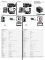
Abmessungen
Elektrischer Anschluss/Kurven/Zusätzliche Informationen Electrical Connection / Curves / Additional Information
Dimensions
Technische Daten
Technical data
PCV100-F200-SSI-V19
7
1
2
3
45
6
8
7
1
2
3
45
6
8
70
80
38.5
70 14.5
1
2
22
51
ø 25
12
M12 x 1
9
4 x M6
40
7
1
2
3
45
6
8
7
1
2
3
45
6
8
70
80
38.5
70 14.5
1
2
22
51
ø 25
12
M12 x 1
9
4 x M6
40
1
2
3
4
5
6
7
8
OUT 2 / IN 2
+ UB
Data +
Data -
CLK+
CLK-
GND
OUT 3 / IN 3
1
4
6
7
8
53
2
X
Z
Y
Koordinaten
COM SERVICE
SSI DATA / CONFIG
OUT2 / ADJ Y
OUT3 / ADJ Z
PWR / ADJ
ERR / NO CODE
INTERNAL
DIAGNOSTIC
ADJUST
CONFIG
1
2
LED 1 2 3 4 5 6 7
COM SERVICE
SSI DATA / CONFIG
OUT2 / ADJ Y
OUT3 / ADJ Z
PWR / ADJ
ERR / NO CODE
INTERNAL
DIAGNOSTIC
ADJUST
CONFIG
1
2
LED 1 2 3 4 5 6 7
X
Z
Y
Coordinates
1
2
3
4
5
6
7
8
OUT 2 / IN 2
+ UB
Data +
Data -
CLK+
CLK-
GND
OUT 3 / IN 3
1
4
6
7
8
53
2
Partnummer / Part.
Datum /
236998
03/28/2017 DIN A3 ->
45-3666H
Doc.
Allgemeine Daten
Überfahrgeschwindigkeit v ≤ 8 m/s
Messlänge max. 10000 m
Lichtart Integrierter LED-Blitz (rot)
Leseabstand 100 mm
Schärfentiefe ± 20 mm
Lesefeld 50 mm x 30 mm
Fremdlichtgrenze 100000 Lux
Auflösung ± 0,1 mm
Kenndaten
Bildaufnehmer
Typ CMOS , Global Shutter
Prozessor
Taktfrequenz 600 MHz
Rechengeschwindigkeit 4800 MIPS
Kenndaten funktionale Sicherheit
MTTF
d
87 a
Gebrauchsdauer (T
M
) 43 a
Diagnosedeckungsgrad (DC) 0 %
Anzeigen/Bedienelemente
LED-Anzeige 7 LEDs (Kommunikation, Ausrichthilfe, Statusmeldungen)
Isolationsspannung
Betriebsspannung U
B
15 ... 30 V DC , PELV
Leerlaufstrom I
0
max. 200 mA
Leistungsaufnahme P
0
3 W
Schnittstelle 1
Schnittstellentyp SSI-Schnittstelle
Ausgabecode Gray-Code, Binär-Code , parametrierbar
Monoflopzeit T
m
= 10 µs
Taktrate 100 ... 1000 kHz
Anfragezykluszeit ≥ 3 ms
Pausenzeit tp ≥ 20 µs
Doppelabfrage möglich, wenn t
p
≤ 10 µs
Schnittstelle 2
Schnittstellentyp USB (seriell comport)
Protokoll 8E1
Übertragungsrate 38,4 ... 460,8 kBit/s
Eingang
Eingangstyp 1 bis 2 Funktionseingänge , parametrierbar
Eingangsimpedanz ≥ 27 kΩ
Ausgang
Ausgangstyp 1 bis 2 Schaltausgänge , PNP , parametrierbar , kurzschlussfest
Schaltspannung Betriebsspannung
Schaltstrom 150 mA je Ausgang
Normenkonformität
Störaussendung EN 61000-6-4:2007+A1:2011
Störfestigkeit EN 61000-6-2:2005
Schockfestigkeit EN 60068-2-27:2009
Schwingungsfestigkeit EN 60068-2-6:2008
Umgebungsbedingungen
Betriebstemperatur 0 ... 60 °C (32 ... 140 °F) , -20 ... 60 °C (-4 ... 140 °F) (nicht kondensierend; Eisbildung an der
Frontscheibe vermeiden!)
Lagertemperatur -20 ... 85 °C (-4 ... 185 °F)
Relative Luftfeuchtigkeit 90 % , nicht kondensierend
General specifications
Passage speed v ≤ 8 m/s
Measuring range max. 10000 m
Light type Integrated LED lightning (red)
Read distance 100 mm
Depth of focus ± 20 mm
Reading field 50 mm x 30 mm
Ambient light limit 100000 Lux
Resolution ± 0.1 mm
Nominal ratings
Camera
Type CMOS , Global shutter
Processor
Clock pulse frequency 600 MHz
Speed of computation 4800 MIPS
Functional safety related parameters
MTTF
d
87 a
Mission Time (T
M
) 43 a
Diagnostic Coverage (DC) 0 %
Indicators/operating means
LED indicator 7 LEDs (communication, alignment aid, status information)
Insulation voltage
Operating voltage U
B
15 ... 30 V DC , PELV
No-load supply current I
0
max. 200 mA
Power consumption P
0
3 W
Interface 1
Interface type SSI interface
Data output code Gray code, binary code , programmable
Monoflop time T
m
= 10 µs
Clock frequency 100 ... 1000 kHz
Query cycle time ≥ 3 ms
Pause time tp ≥ 20 µs
double request possible, if t
p
≤ 10 µs
Interface 2
Interface type USB (serial comport)
Protocol 8E1
Transfer rate 38.4 ... 460.8 kBit/s
Input
Input type 1 to 2 functional inputs , programmable
Input impedance ≥ 27 kΩ
Output
Output type 1 to 2 switch outputs , PNP , programmable , short-circuit protected
Switching voltage Operating voltage
Switching current 150 mA each output
Standard conformity
Emitted interference EN 61000-6-4:2007+A1:2011
Noise immunity EN 61000-6-2:2005
Shock resistance EN 60068-2-27:2009
Vibration resistance EN 60068-2-6:2008
Ambient conditions
Operating temperature 0 ... 60 °C (32 ... 140 °F) , -20 ... 60 °C (-4 ... 140 °F) (noncondensing; prevent icing on the lens!)
Storage temperature -20 ... 85 °C (-4 ... 185 °F)
Relative humidity 90 % , noncondensing
Optischer Lesekopf
Optical reading head
Alle Abmessungen in mm All dimensions im mm

Adressen / Addresses / Adresses / Direcciónes / Indirizzi
Contact Pepperl+Fuchs GmbH · 68301 Mannheim · Germany · Tel. +49 621 776-4411 · Fax +49 621 776-27-4411 · E-mail: fa-info@de.pepperl-fuchs.com
Worldwide Headquarters: Pepperl+Fuchs GmbH · Mannheim · Germany · E-mail: info@de.pepperl-fuchs.com
USA Headquarters: Pepperl+Fuchs Inc. · Twinsburg · USA · E-mail: fa-info@us.pepperl-fuchs.com
Asia Pacific Headquarters: Pepperl+Fuchs Pte Ltd · Singapore · E-mail: fa-info@sg.pepperl-fuchs.com · Company Registration No. 199003130E
For more contact-adresses refer to the catalogue or internet: http://www.pepperl-fuchs.com
Allgemeines
Der Lesekopf PCV... ist Teil des Positioniersystems im Auflichtverfahren von Pepperl+Fuchs. Er besteht unter anderem aus einem Kameramodul
und einer integrierten Beleuchtungseinheit. Damit erfasst der Lesekopf Positionsmarken, welche in Form von DataMatrix-Codes auf einem
selbstklebenden Codeband aufgebracht sind. Die Montage des Codebandes erfolgt in der Regel stationär an einem festen Teil der Anlage
(Fahrstuhlschacht, Tragschiene einer EHB …) - die des Lesekopfes an einem sich parallel dazu beweglichen "Fahrzeug" (Fahrstuhlkabine,
Fahrwerk einer EHB …).
Montage und Inbetriebnahme
Montieren Sie den Lesekopf so, dass seine optische Fläche den optimalen Leseabstand zum Codeband einnimmt (siehe Technische Daten). Die
Stabilität der Montage und die Führung des Fahrzeuges muss so beschaffen sein, dass im laufenden Betrieb der Tiefenschärfebereich des
Lesekopfes nicht verlassen wird.
Alle Leseköpfe lassen sich durch Parametrieren optimal an die spezifischen Anforderungen anpassen.
Anzeigen und Bedienelemente
Der Lesekopf PCV... ist zur optischen Funktionskontrolle und zur schnellen Diagnose mit 7 Anzeige-LEDs ausgestattet. Für die Aktivierung der
Ausrichthilfe und des Parametriermodus verfügt der Lesekopf über 2 Tasten an der Geräterückseite.
LEDs
Datenprotokoll
Positionsdaten kodiert in XP0 ... XP21 (MSB zuerst)
Bedeutung der Statusbits
Error codes
Externe Parametrierung
Für die externe Parametrierung benötigen Sie den Parametriercode als Datamatrix mit den gewünschten Lesekopf-Parametern. Datamatrix
Codekarten für die schrittweise externe Parametrierung sind in der Betriebsanleitung des Lesekopfes abgedruckt.
Eine Parametrierung ist nur innerhalb von 10 Minuten nach dem Einschalten des Lesekopfes möglich. Erfolgt ein Tastendruck nach Ablauf von
10 Minuten nach dem Einschalten, erfolgt eine optische Signalisierung durch die LEDs (LED1, gelb/LED2, rot/LED3, gelb/LED4, gelb/LED5, gelb
blinken für 2 Sekunden)
• Die Umschaltung vom Normalbetrieb in den Parametriermodus erfolgt über die Taste 2 an der Rückseite des Lesekopfes. Die Taste 2 muss
dazu länger als 2 Sekunden gedrückt werden. Die LED3 blinkt nun.
Hinweis: Nach 1 Minute Inaktivität wird der Parametriermodus automatisch verlassen. Der Lesekopf kehrt in den Normalbetrieb zurück
und arbeitet mit unveränderten Einstellungen.
• Bringen Sie den Parametriercode in das Sichtfeld des Kameramoduls. Nach Erkennen des Parametriercodes leuchtet die grüne LED2 1s
lang. Bei ungültigem Parametriercode leuchtet die LED2 für 2 Sekunden rot.
• Ein kurzer Druck auf die Taste 2 beendet den Parametriermodus und die geänderten Parameter werden nicht flüchtig im Lesekopf ab-
gespeichert.
Ausrichthilfe für die Y- und Z-Koordinate
Die Aktivierung der Ausrichthilfe ist nur innerhalb von 10 Minuten nach dem Einschalten des Lesekopfes möglich. Die Umschaltung vom
Normalbetrieb in die Betriebsart „Ausrichthilfe“ erfolgt über die Taste 1 an der Rückseite des Lesekopfes.
• Drücken Sie die Taste 1 länger als 2 Sekunden. Die LED2 blinkt bei erkanntem Codeband in der Farbe grün. Bei nicht erkanntem Codeband
blinkt die LED2 rot.
• Z-Koordinate: Ist der Abstand der Kamera zum Codeband zu klein, leuchtet die gelbe LED5. Ist der Abstand zu groß, erlischt die gelbe
LED5. Innerhalb des Sollbereichs blinkt die gelbe LED5 im Gleichtakt zur grünen LED2.
• Y-Koordinate: Liegt die optische Achse der Kamera zu tief relativ zur Codebandmitte, leuchtet die gelbe LED4. Liegt die optische Achse
zu hoch, erlischt die gelbe LED4. Im Sollbereich blinkt die gelbe LED4 im Gleichtakt zur grünen LED2.
• Ein kurzer Druck auf die Taste 1 beendet die Ausrichthilfe und der Lesekopf wechselt in den Normalbetrieb.
Default-Werte
Die Parameter des Lesekopfs PCV...-SSI-* haben im Auslieferungszustand die folgenden Default-Werte:
Mechanische Daten
Anschlussart Gerätestecker M12 x 1, 8-polig
Gehäusebreite 70 mm
Gehäusehöhe 70 mm
Schutzart IP67
Material
Gehäuse PC/ABS
Masse ca. 160 g
Zulassungen und Zertifikate
EAC-Konformität TR CU 020/2011
UL-Zulassung cULus Listed, General Purpose, Class 2 Power Source, Type 1 enclosure
CCC-Zulassung Produkte, deren max. Betriebsspannung ≤36 V ist, sind nicht zulassungspflichtig und daher nicht
mit einer CCC-Kennzeichnung versehen.
LED Farbe Beschriftung Bedeutung
1 gelb COM Kommunikation aktiv auf USB-Schnittstelle
2 grün/rot PWR/ADJ
ERR/NO CODE
Code erkannt/nicht erkannt, Error
3 gelb SSI DATA/CONFIG Datenfluss auf SSI-Schnittstelle/Konfiguration
4 gelb OUT2/ADJ Y Ausgang 2, Ausrichthilfe Y
5 gelb OUT3/ADJ Z Ausgang 3, Ausrichthilfe Z
6,7 rot/grün/gelb INTERNAL
DIAGNOSTIC
interne Diagnose
1 2 3 4 5 6 7 8 9 10 11 12 13 14 15 16 17 18 19 20 21 22 23 24 25
Data XP21XP20XP19XP18XP17XP16XP15XP14XP13XP12XP11XP10 XP9 XP8 XP7 XP6 XP5 XP4 XP3 XP2 XP1 XP0 Out Wrn Err
MSB LSB Status bits
Out Err Wrn Bedeutung
X X 1 reserviert
X 1 X Fehler, Fehlercode in XP0 ... XP21
1 X X Keine Positionscodes im Lesefenster (XP0 ... XP21 = 0)
Fehlercode Bedeutung
1 falsche Orientierung des Lesekopfs (180° verdreht)
2 Positionsfehler: Positionscodes im Lesefenster sind uneindeutig
>1000 interner Fehler
Parameter Default-Wert
X-Auflösung 1 mm
Y-Auflösung 1 mm
Orientierung 0°
Codebandbreite 2-reihig
X-Position Offset 0
X-Wert bei „No Position“ 0
Y-Wert bei „No Position“ 0
Geschwindigkeitswert bei „No Position“ 127
Übergeschwindigkeitsschwelle bzgl. Protokoll 12,5 m/s
X-Wert bei „Error“ Fehlernummer
Y-Wert bei „Error“ Fehlernummer
Geschwindigkeitswert bei „Error“ Fehlernummer
Input / Output Inaktiv
SSI-Code Binär
General
The PCV… reading head is part of the positioning system in the method for measurement by Pepperl+Fuchs. It consists of a camera module and an
integrated illumination unit among other things. The reading head detects position marks, which are put on an adhesive code band in the form of Data
Matrix code. The mounting of the code band is as a rule stationary on a firm part of the plant (elevator shaft, overhead conveyor mounting rails…); that
of the reading head is parallel on the moving "vehicle" (elevator car, overhead conveyor chassis…).
Mounting and commissioning
Mount the reading head such that its optical surface captures the optimal read distance to the code band (see Technical Data). The stability of the
mounting and the guidance of the vehicle must be provided such that the depth of field of the reading head is not closed during operation.
All reading heads can be optimally customized by parameterization for specific requirements.
Displays and Controls
The PCV... reading head allows visual function check and fast diagnosis with 7 indicator LEDs. The reading head has 2 buttons on the reverse of the
device to activate the alignment aid and parameterization mode.
LEDs
Data protocol
Position data is coded in XP0 ... XP21 (MSB first)
Meaning of the status bits
Error codes
External parameterization
For external parameterization you require the parameterization code as Data Matrix with the desired reading head parameters. Data Matrix code cards
for step-by-step external parameterization are printed in the reading heads operating instructions.
Parameterization is only possible within 10 minutes of switching on the reading head. If a button is pressed after 10 minutes subsequent to switching
on, there is visual signaling via the LEDs (LED1, yellow/LED2, red/LED3, yellow/LED4, yellow/LED5, yellow flash for 2 seconds)
• The switchover from normal operation to parameterization mode is via button 2 on the reverse of the reading head. Button 2 must be pressed
for more than 2 seconds. LED3 now flashes.
Note:Parameterization mode automatically ends after 1 minute of inactivity. The reading head returns to normal operation and works with un-
changed settings.
• Place the parameterization code in the view of the camera module. After recognition of the parameterization code, the green LED2 lights up for
1s. In the event of an invalid parameterization code, the red LED2 lights up for 2 s.
• A short press on button 2 ends the parameterization mode and the changed parameters are not stored volatile in the reading head.
Alignment aid for the Y and Z coordinates
The activation of the alignment aid is only possible within 10 minutes of switching on the reading head. The switchover from normal operation to
“alignment aid operating mode is via button 1 on the reverse of the reading head.
• Press the button 1 for longer than 2 s. LED2 flashes green for a recognized code band. LED2 flashes red for an unrecognized code band.
• Z coordinate: If the distance of the camera to the code band too small, the yellow LED5 lights up. If the distance of the camera to the code band
too large, the yellow LED5 lights up. Within the target range, the yellow LED5 flashes at the same time as the green LED2.
• Y coordinate: If the optical axis of the camera is too deep in relation to the middle of the code band, the yellow LED4 lights up. If the optical axis
is too high, the yellow LED4 extinguishes. Within the target range, the yellow LED4 flashes at the same time as the green LED2.
• A short press on button 1 ends the alignment aid and the reading head changes to normal operation.
Default values
On delivery the parameters of the read head PCV...-SSI-* have the following default values:
Mechanical specifications
Connection type 8-pin, M12 x 1 connector
Housing width 70 mm
Housing height 70 mm
Degree of protection IP67
Material
Housing PC/ABS
Mass approx. 160 g
Approvals and certificates
EAC conformity TR CU 020/2011
UL approval cULus Listed, General Purpose, Class 2 Power Source, Type 1 enclosure
CCC approval CCC approval / marking not required for products rated ≤36 V
LED Color Label Meaning
1 Yellow COM USB interface, communication active
2 Green/red PWR/ADJ
ERR/NO CODE
Code recognized/not recognized, Error
3 Yellow SSI DATA/CONFIG Data flow on SSI interface / configuration
4 Yellow OUT2/ADJ Y Output 2, Alignment aid Y
5 Yellow OUT3/ADJ Z Output 3, Alignment aid Z
6,7 red/green/yellow INTERNAL
DIAGNOSTICS
Internal diagnostics
1 2 3 4 5 6 7 8 9 10 11 12 13 14 15 16 17 18 19 20 21 22 23 24 25
Data XP21XP20XP19XP18XP17XP16XP15XP14XP13XP12XP11XP10 XP9 XP8 XP7 XP6 XP5 XP4 XP3 XP2 XP1 XP0 Out Wrn Err
MSB LSB Status bits
Out Err Wrn Meaning
X X 1 reserved
X 1 X Error, error code in XP0 ... XP21
1 X X No codes in read window (XP0 ... XP21 = 0)
Error code Meaning
1 reverse reading head orientation (180° contorted)
2 position error: unsecure position codes in reading window
>1000 internal error
Parameter Default values
X-Resolution 1 mm
Y-Resolution 1 mm
Orientation 0°
Width code reel 2-row
X-Position Offset 0
X value for „No Position“ 0
Y value for „No Position“ 0
Speed value for „No Position“ 127
Overspeed threshold regarding protocol 12.5 m/s
X value for „Error“ Error number
Y value for „Error“ Error number
Speed value for „Error“ Error number
Input / output Inactive
SSI code Binary
-
 1
1
-
 2
2


Pepperl+Fuchs PCV100-F200-SSI-V19 Bedienungsanleitung
- Typ
- Bedienungsanleitung
in anderen Sprachen
Verwandte Artikel
-
Pepperl+Fuchs PCV80S-F200-SSI-V19 Bedienungsanleitung
-
-
-
-
-
-
-
-
-