Sunny SF-B1423 Benutzerhandbuch
- Kategorie
- Spinbikes
- Typ
- Benutzerhandbuch

BELT DRIVE
INDOOR CYCLING BIKE
SF-B1423
USER MANUAL
English, Page 9~16 IMPORTANT! Please retain owner’s manual for maintenance and adjustment instructions. Your satisfaction is
very important to us, PLEASE DO NOT RETURN UNTIL YOU HAVE CONTACTED US:
support@sunnyhealthfitness.com or 1- 877 - 90SUNNY (877-907- 8669).
Español, Page 17~24 ¡IMPORTANTE! Conserve el manual del propietario para las instrucciones de mantenimiento y ajuste. Su
satisfacción es muy importante para nosotros, NO DEVUELVA HASTA HABERNOS CONTACTADO:
support@sunnyhealthfitness.com ó 1- 877 - 90SUNNY (877-907-8669).
Français, Page 25~32 IMPORTANT! Veuillez conserver le manuel du propriétaire pour les instructions de réglage et d’entretien. Votre
satisfaction est très importante pour nous, VEUILLEZ NE PAS EFFECTUER DE RETOUR AVANT DE NOUS
AVOIR CONTACTÉ: support@sunnyhealthfitness.com ou 1- 877 – 90SUNNY (877-907-8669).
Deutsch, Seite 33~40 WICHTIG! Bitte bewahren Sie das Benutzerhandbuch für Wartungs- und Einstellanweisungen auf. Ihre
Zufriedenheit ist besonders wichtig für uns, BITTE SCHICKEN SIE DAS PRODUKT NICHT ZURÜCK, BEVOR
SIE SICH MIT UNS IN VERBINDUNG GESETZT HABEN: support@sunnyhealthfitness.com oder 1- 877 -
90SUNNY (877-907- 8669).

1
IMPORTANT SAFETY INFORMATION
We thank you for choosing our product. To ensure your safety and health, please use this equipment correctly. It is important to read this entire manual
before assembling and using the equipment. Safe and effective use can only be achieved if the equipment is assembled, maintained, and used
properly. It is your responsibility to ensure that all users of the equipment are informed of all warnings and precautions.
1. Before starting any exercise program, you should consult your physician to determine if you have any medical or physical conditions that could
put your health and safety at risk or prevent you from using the equipment properly. Your physician’s advice is essential if you are taking medication
that affects your heart rate, blood pressure, or cholesterol level.
2. Be aware of your body’s signals. Incorrect or excessive exercise can damage your health. Stop exercising if you experience any of the following
symptoms: pain, tightness in your chest, irregular heartbeat, shortness of breath, lightheadedness, dizziness, or feelings of nausea. If you do
experience any of these conditions, you should consult your physician before continuing with your exercise program.
3. Keep children and pets away from the equipment. The equipment is designed for adult use only.
4. Use the equipment on a solid, flat level surface with a protective cover for your floor or carpet. To ensure safety, the equipment should have at
least 2 feet (60 CM) of free space all around it.
5. Ensure that all nuts and bolts are securely tightened before using the equipment. The safety of the equipment can only be maintained if it is
regularly examined for damage and/or wear and tear.
6. Always use the equipment as indicated. If you find any defective components while assembling or checking the equipment, or if you hear any
unusual noises coming from the equipment during exercise, discontinue use of the equipment immediately and do not use until the problem has
been rectified.
7. Wear suitable clothing while using the equipment. Avoid wearing loose clothing that may become entangled in the equipment.
8. Do not place fingers or objects into the moving parts of the equipment.
9. The maximum weight capacity of this unit is 265 pounds (120 KG).
10. The equipment is not suitable for therapeutic use.
11. To avoid bodily injury and/or damage to the product or property, proper lifting and moving are required.
12. Your product is intended for use in cool and dry conditions. You should avoid storage in extreme cold, hot or damp areas as this may lead to
corrosion and other related problems.
13. This equipment is designed for indoor and home use only; it is not intended for commercial use.
INFORMACIÓN IMPORTANTE DE SEGURIDAD
Gracias por haber elegido nuestro producto. Para garantizar su seguridad y salud, utilice este equipo correctamente. Es importante leer todo el
manual antes de instalar y usar el equipo. Solo se puede garantizar el uso seguro y eficaz del equipo si se instala, mantiene y utiliza correctamente.
Es su responsabilidad asegurarse de que todos los usuarios de los equipos conozcan todas las advertencias y precauciones.
1. Antes de comenzar cualquier programa de ejercicios, consulta con su médico para determinar si tiene alguna condición médica o física que puede
poner en riesgo su salud y seguridad o que podría impedir que utilice el equipo adecuadamente. El consejo de su médico es esencial en caso de
que esté tomando algún medicamento que podría afectar su ritmo cardíaco, presión arterial o nivel de colesterol.
2. Esté atento a las señales de su cuerpo. Ejercitarse de manera incorrecta o excesiva puede dañar su salud. Deje de hacer ejercicio si experimenta
alguno de los siguientes síntomas: dolor, opresión en el pecho, latidos cardíacos irregulares, falta de aliento, sensación de desmayo, mareos o
sensación de náuseas. Si presenta alguna de esas condiciones, consulta con su médico antes de continuar con su programa de ejercicios.
3. Mantenga el equipo lejos del alcance de niños y mascotas. El equipo está diseñado para el uso exclusivo de adultos.
4. Utilice el equipo en una superficie plana y sólida con una cubierta protectora para su piso o alfombra. Para garantizar su seguridad, el equipo
debe tener al menos 60CM (2 pies) de espacio libre a su alrededor.
5. Asegúrese de que todas las tuercas y pernos estén bien ajustados antes de usar el equipo. Solo puede conservarse la seguridad del equipo si
se inspecciona regularmente para detectar daños o desgaste.
6. Siempre utilice el equipo como se indica. Si encuentra algún componente defectuoso mientras instala o revisa el equipo, o si escucha ruidos
extraños que provienen del equipo durante el ejercicio, deje de utilizarlo inmediatamente y no lo utilice hasta que el problema se ha corregido.
7. Use ropa adecuada cuando utilice el equipo. Evite usar ropa suelta que pueda enredarse en el equipo.
8. No coloque los dedos u objetos en las partes móviles del equipo.
9. La capacidad máxima de peso de esta unidad es de 120 KG (265 libras).
10. El equipo no es adecuado para uso terapéutico.
11. Muévase con cuidado cuando levante y mueva el equipo a fin de que no se dañe la espalda. Siempre utilice la técnica de levantamiento adecuada
y pida ayuda en caso de que sea necesario.
12. Su producto está diseñado para usar en condiciones frescas y secas. Debe evitar de tenerlo en lugares extremadamente frías, calientes o
húmedas, ya que pueden provocar corrosión y otros problemas relacionados.
13. ¡Este equipo está diseñado solamente para uso interior! ¡No es para uso comercial!

2
INFORMATIONS DE SÉCURITÉ IMPORTANTES
Nous vous remercions d’avoir choisi notre produit. Pour votre santé et votre sécurité, veuillez utiliser correctement cet appareil. Il est important de lire
entièrement le présent manuel avant d’assembler l’appareil et de l’utiliser. L’utilisation sûre et efficace n’est possible que si l’appareil est correctement
assemblé, entretenu et utilisé. Il vous incombe de vous assurer que tous les utilisateurs de l’appareil soient informés de tous les avertissements et
précautions.
1. Avant d’entamer un programme d’exercices, consultez votre médecin pour déterminer si vous avez une quelconque disposition physique ou
médicale susceptible de mettre en danger votre santé et votre sécurité ou de vous empêcher d’utiliser cet appareil correctement. L’avis de votre
médecin est essentiel si vous prenez un médicament pouvant affecter le rythme cardiaque, la pression ou le niveau de cholestérol.
2. Soyez conscient des signaux de votre corps. Des exercices incorrects ou excessifs peuvent nuire à votre santé. Arrêtez l'exercice si vous ressentez
l'un des symptômes suivants : douleur, oppression thoracique, pouls irrégulier, essoufflement, étourdissements, vertiges ou nausées. Si vous
rencontrez l'une de ces conditions, vous devriez consulter votre médecin avant de poursuivre votre programme d'exercices
3. Gardez les enfants et les animaux de compagnie à distance de l’appareil. L’appareil est conçu pour l’utilisation exclusive par des adultes.
4. Utilisez l’appareil sur une surface dure, plane et de niveau, avec une protection pour votre parquet ou tapis. Pour un usage sûr, l’appareil doit
disposer d’au moins 60 cm (2 pi) d’espace libre tout autour de lui.
5. Assurez-vous que tous les boulons et écrous soient bien serrés avant d’utiliser l’appareil. La sécurité de l’appareil ne peut être entretenue qu’à
condition de régulièrement vérifier l’absence de dommages ou d’usure.
6. Utilisez toujours l'équipement comme indiqué. Si vous trouvez des composants défectueux lors de l'assemblage ou du contrôle de l'équipement,
ou si vous entendez des bruits inhabituels provenant de l'équipement pendant l'exercice, arrêtez immédiatement d'utiliser l'équipement et n'utilisez
plus jusqu'à ce que le problème soit résolu.
7. Portez des vêtements adéquats lors de l’utilisation de l’appareil. Évitez les vêtements amples qui risqueraient de se prendre dans l’appareil.
8. Ne mettez pas le doigt ni aucun objet dans les pièces mobiles de l’appareil.
9. La capacité de poids maximale de cet appareil est de 120 kg (265lb).
10. Cet appareil n’est pas adapté à un usage thérapeutique.
11. Soulevez et déplacez l’appareil avec précaution. Utilisez toujours les techniques adéquates de levage et demandez de l’aide si nécessaire.
12. Votre produit est conçu pour usage dans un endroit sec et frais. Éviter de l’entreposer dans un endroit extrêmement froid, chaud ou humide, car
cela peut entraîner de la corrosion et des problèmes du même ordre.
13. Cet appareil est conçu pour un usage intérieur uniquement; Il n’est pas fait pour une utilisation commerciale.
WICHTIGE SICHERHEITSHINWEISE
Wir danken Ihnen, dass Sie sich für unser Produkt entschieden haben. Zur Gewährleistung Ihrer Sicherheit und Gesundheit verwenden Sie dieses
Gerät bitte ordnungsgemäß. Es ist wichtig, diese gesamte Bedienungsanleitung zu lesen, bevor Sie das Gerät montieren und in Betrieb nehmen.
Eine sichere und effektive Nutzung kann nur erreicht werden, wenn das Gerät ordnungsgemäß montiert, gewartet und verwendet wird. Sie sind dafür
verantwortlich, dass alle Benutzer des Geräts über alle Warnungen und Vorsichtsmaßnahmen informiert werden.
1. Vor Beginn eines jeden Trainingsprogramms ist es ratsam, einen Arzt zu konsultieren, um festzustellen, ob Sie medizinische oder körperliche
Beschwerden haben, die Ihre Gesundheit und Sicherheit gefährden oder verhindern könnten, dass Sie das Gerät ordnungsgemäß benutzen. Der
Rat Ihres Arztes ist unerlässlich, wenn Sie Medikamente einnehmen, die Ihre Herzfrequenz, Ihren Blutdruck oder Ihren Cholesterinspiegel
beeinflussen.
2. Achten Sie auf die Signale Ihres Körpers. Falsches oder übermäßiges Training kann Ihre Gesundheit schädigen. Hören Sie auf zu trainieren,
wenn Sie eines der folgenden Symptome verspüren: Schmerzen, Engegefühl in Ihrer Brust, unregelmäßiger Herzschlag, Kurzatmigkeit,
Benommenheit, Schwindel oder Übelkeit. Wenn Sie einen dieser Zustände bemerken, sollten Sie Ihren Arzt konsultieren, bevor Sie mit Ihrem
Trainingsprogramm fortfahren.
3. Kinder und Haustiere dürfen nicht in der Nähe des Geräts sein. Das Gerät ist nur für den Gebrauch durch Erwachsene bestimmt.
4. Verwenden Sie das Gerät auf einer festen, ebenen Fläche mit einer Schutzabdeckung für Ihren Boden oder Teppich. Um die Sicherheit zu
gewährleisten, sollte das Gerät ringsum mindestens 60 cm (2 ft) Freiraum haben.
5. Vergewissern Sie sich, dass alle Muttern und Bolzen fest angezogen sind, bevor Sie das Gerät benutzen. Die Sicherheit des Gerätes kann nur
gewährleistet werden, wenn es regelmäßig auf Beschädigungen und/oder Verschleiß überprüft wird.
6. Verwenden Sie das Gerät immer entsprechend den Angaben. Wenn Sie bei der Montage oder Überprüfung des Geräts defekte Komponenten
feststellen oder ungewöhnliche Geräusche vom Gerät während des Trainings hören, stellen Sie die Verwendung des Geräts sofort ein. In diesem
Fall sollten Sie es erst dann wieder in Betrieb nehmen, wenn das Problem behoben ist.
7. Tragen Sie bei der Benutzung des Gerätes geeignete Kleidung. Vermeiden Sie das Tragen von loser Kleidung, die sich in der Ausrüstung
verfangen kann.
8. Stecken Sie keine Finger oder Gegenstände in die beweglichen Teile des Gerätes.
9. Die maximale Gewichtsbelastbarkeit dieser Einheit beträgt 120 kg (265 Pfund).
10. Dieses Gerät ist nicht für den therapeutischen Einsatz geeignet.
11. Um Personenschäden und/oder Schäden am Produkt oder Eigentum zu vermeiden, ist ein ordnungsgemäßes Hochheben und Transportieren
erforderlich.
12. Ihr Produkt ist für den Einsatz unter kühlen und trockenen Bedingungen bestimmt. Sie sollten die Lagerung in extrem kalten, heißen oder feuchten
Räumen vermeiden, da dies zu Korrosion und anderen damit verbundenen Problemen führen kann.
13. Dieses Gerät ist nur für den Innen- und Heimgebrauch bestimmt; es ist nicht für die gewerbliche Nutzung bestimmt.

3
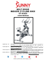
EXPLODED DIAGRAM
HARDWARE PACKAGE
#83 M5*10 1PC
#88 S13-S14-S15 1PC
#6 M10*35*15*H6 2PCS #11 M10*H9.5*S17 2PCS
#76 M8*40*20*S5 4PCS #77 φ8.4*φ16*1.6 4PCS
#89 S10-13-17-22 1PC
#87 S5-S6 1PC
#38 M16*1.5 1PC

4
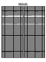
PARTS LIST
No.
Description
Spec.
Qty.
No.
Description
Spec.
Qty.
1
Foam (A)
Φ23*3*550
1
50
Screw
ST4.2*16*Φ8
3
2
Tablet Bracket
1
51
Belt Wheel
Φ204*21*5PK
1
3
Handlebar (A)
1
52
Middle Axle
1
4
End Cap
Φ25*16
2
53
Screw
M10*16*S6
4
5
Screw
M6*16*S4
4
54
Belt
5PK520
1
6
Bolt
M10*35*15*H6
2
55
Screw
ST4.2*13*Φ8
9
7
Foam Grip
Φ23*3*460
2
56
Outer Belt Cover
648*264*45
1
8
Handlebar (B)
1
57
Nut
M12*1*H19.5*S19
2
9 Computer 1 58 Inertial Axle Φ15*165*72*M12*1
*33.5
1
10
Handlebar Post
1
59
Spacer
Φ22*Φ12.5*6
2
11
Nut
M10*H9.5*S17
2
60
Adjusting Screw
M6*50*Φ12*5
2
12
Nut
M8
4
61
Nut
M6*H5*S10
2
13
End Cap
F30*30*16
3
62
Nut
M6*H6*S10
2
14
Bushing
F38*F30*153.3
3
63
Nut
M12*1*H6*S19
3
15
Tension Control Knob
Φ58*44*M8*18
1
64
Bearing
6202-2RS C&U
3
16 Brake Rod Φ10*210*M8*15*M6
*7*M10*95
1 65 Inertial Wheel 18*Φ460*75*30*Φ5
5*42*PK
1
17
Bushing
20*20*65
1
66
Spacer
Φ18*Φ12.2*4
1
18
Washer
D6*Φ12*1.2
2
67
Inductor
1
19
Square Nut
15*15*25*M10
1
68
Magnet
1
20
Nut
M8*H5.5*S14
1
69
Washer
D5*Φ13*1.0
4
21
Spring
Φ2.0*Φ15*54*N12
1
70
Water Bottle Holder
1
22
Decorative Cover
195*161*31
1
71
Washer
D5*Φ13*1
2
23
Nut
M10*H5.5*S17
1
72
Screw
M5*15*Φ10
2
24
Nut
M6*H11*S10
1
73
Front Stabilizer
1
25
Brake Stopper
35*24*2
1
74
Foot Leveler
Φ43*14*M8*25
4
26
Spring
Φ2*Φ24*Φ13*17*N4
1
75
End Cap
30*70*1.5t
4
27
Brake Block
110*27*30
1
76
Screw
M8*40*20*S5
6
28
Washer
D5*Φ10*1
2
77
Washer
Φ8.4*Φ16*1.6
6
29
Nut
M5*H5.5*S10
2
78
Transportation Wheel
Φ42*18*Φ8*22
2
30
Screw
M5*30*Φ8
2
79
Nut
M8*H7.5*S13
2
31
Woolen Felt
110*30*10
1
80
Washer
D8*Φ16*1.5
2
32
Spring Piece
T2*59*185
1
81
Screw
ST4.8*10*Φ8
4
33
Rubber Mat
35*20*3
1
82
Front Shipping Tube
1
34
Bolt
M6*12*S10
2
83
Screw
M5*10
1
35
Seat
98-2
1
84
Rear Stabilizer
1
36
Seat Slider
1
85
Main Frame
1
37
Seat Post
1
86
Spacer
Φ21.8*Φ12.2*11.5
1
38
Adjustment Knob
M16*1.5
3
87
Allen Wrench
S5-S6
1
39
Grommet
Φ12*11*Φ3
2
88
Spanner
S13-14-15
1
40
Screw
M6*10*Φ12
2
89
Spanner
S10-13-17-22
1
41
Front Cover
157*152*38.5 HIPS
1
90L/R
Nylon Nut
9/16*20*H8*S22
2
42
Crank Cap
Φ25*7
2
91
Trunk Wire
1
43
Nut
M10*1.25*H7.5*S14
2
92L/R
Pedal
YH-102 9/16"
2
44L/R
(Refer to Part #92 L/R)
-
93
Spacer
Φ22*Φ15.1*39.1
1
45L/R
Crank
170 “L/R” 9/16
2
94
Spacer
Φ22*Φ17.1*5.5
1
46
Cover for Middle Axle
Φ50*Φ32*33
1
95
Wave Washer
Φ17.5*Φ23*0.3
1
47
C-clip
D17
1
96
Spacer
Φ22*Φ17.1*10
1
48
Bearing
6203-2RS
2
97
Screw
M8*15
2
49
Inner Belt Cover
504*259*23
1
98
Rear Shipping Tube
1

5
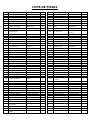
LISTA DE PIEZAS
n.°
Descripción
Especificaciones
Cant.
n.°
Descripción
Especificaciones
Cant.
1
Espuma (A)
Φ23*3*550
1
50
Tornillo
ST4.2*16*Φ8
3
2
Cobertor del Manubrio
1
51
Rueda de la Cinta
Φ204*21*5PK
1
3
Manubrio (A)
1
52
Eje Medio
1
4
Tapón
Φ25*16
2
53
Tornillo
M10*16*S6
4
5
Tornillo
M6*16*S4
4
54
Cinta
5PK520
1
6
Perno
M10*35*15*H6
2
55
Tornillo
ST4.2*13*Φ8
9
7 Agarre de Espuma Φ23*3*460 2 56 Cubierta Externa de la
Cinta
648*264*45 1
8
Manubrio (B)
1
57
Tuerca
M12*1*H19.5*S19
2
9 Computadora 1 58 Eje de Inercia Φ15*165*72*M12*
1*33.5
1
10
Barral del Manubrio
1
59
Espaciador
Φ22*Φ12.5*6
2
11
Tuerca
M10*H9.5*S17
2
60
Tornillo de Ajuste
M6*50*Φ12*5
2
12
Tuerca
M8
4
61
Tuerca
M6*H5*S10
2
13
Tapón
F30*30*16
3
62
Tuerca
M6*H6*S10
2
14
Buje
F38*F30*153.3
3
63
Tuerca
M12*1*H6*S19
3
15
Perilla de Tensión
Φ58*44*M8*18
1
64
Cojinete
6202-2RS C&U
3
16 Varilla del Freno
Φ10*210*M8*15*M6
*7*M10*95
1 65 Rueda Inercial
18*Φ460*75*30*Φ
55*42*PK
1
17
Buje
20*20*65
1
66
Espaciador
Φ18*Φ12.2*4
1
18
Arandela
D6*Φ12*1.2
2
67
Inductor
1
19
Tuerca Cuadrada
15*15*25*M10
1
68
Imán
1
20
Tuerca
M8*H5.5*S14
1
69
Arandela
D5*Φ13*1.0
4
21
Resorte
Φ2.0*Φ15*54*N12
1
70
Soporte para Botella
1
22
Cubierta Decorativa
195*161*31
1
71
Arandela
D5*Φ13*1
2
23
Tuerca
M10*H5.5*S17
1
72
Tornillo
M5*15*Φ10
2
24
Tuerca
M6*H11*S10
1
73
Estabilizador Delantero
1
25
Tope del Freno
35*24*2
1
74
Niveladores de Pie
Φ43*14*M8*25
4
26
Resorte
Φ2*Φ24*Φ13*17*N4
1
75
Tapón
30*70*1.5t
4
27
Bloque de Freno
110*27*30
1
76
Tornillo
M8*40*20*S5
6
28
Arandela
D5*Φ10*1
2
77
Arandela
Φ8.4*Φ16*1.6
6
29
Tuerca
M5*H5.5*S10
2
78
Rueda de Rodillo
Φ42*18*Φ8*22
2
30
Tornillo
M5*30*Φ8
2
79
Tuerca
M8*H7.5*S13
2
31
Fieltro de Lana
110*30*10
1
80
Arandela
D8*Φ16*1.5
2
32
Pieza de Resorte
T2*59*185
1
81
Tornillo
ST4.8*10*Φ8
4
33 Tapete de Goma 35*20*3 1 82
Tubo de Envío
Delantero
1
34
Perno
M6*12*S10
2
83
Tornillo
M5*10
1
35
Asiento
98-2
1
84
Estabilizador Trasero
1
36
Deslizador del Asiento
1
85
Estructura Principal
1
37
Barral del Asiento
1
86
Espaciador
Φ21.8*Φ12.2*11.5
1
38
Perilla de Ajuste
M16*1.5
3
87
Llave Allen
S5-S6
1
39
Ojal
Φ12*11*Φ3
2
88
Llave Inglesa
S13-14-15
1
40
Tornillo
M6*10*Φ12
2
89
Llave Inglesa
S10-13-17-22
1
41
Cubierta Delantera
157*152*38.5 HIPS
1
90L/R
Tuerca de Nailon
9/16*20*H8*S22
2
42
Tapa de la Manivela
Φ25*7
2
91
Cable Troncal
1
43
Tuerca
M10*1.25*H7.5*S14
2
92L/R
Pedal
YH-102 9/16"
2
44L/R
(Consulte la Parte n.° 92)
93
Espaciador
Φ22*Φ15.1*39.1
1
45L/R
Brazo de la Manivela
170 “L/R” 9/16
2
94
Espaciador
Φ22*Φ17.1*5.5
1
46
Cubierta para el Eje
Intermedio
Φ50*Φ32*33 1 95 Arandela Ondulada Φ17.5*Φ23*0.3 1
47
Clip C
D17
1
96
Espaciador
Φ22*Φ17.1*10
1
48
Cojinete
6203-2RS
2
97
Tornillo
M8*15
2
49
Cubierta Interna de la
Cinta
504*259*23 1 98 Tubo de Envío Trasero 1

6
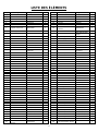
LISTE DES ÉLÉMENTS
N
o
Description
Spécification
Qté.
N
o
Description
Spécification
Qté.
1
Mousse (A)
Φ23*3*550
1
50
Vis
ST4,2*16*Φ8
3
2
Carter du Guidon
1
51
Roue de la Courroie
Φ204*21*5PK
1
3
Guidon (A)
1
52
Axe Central
1
4
Embout d’Extrémité
Φ25*16
2
53
Vis
M10*16*S6
4
5
Vis
M6*16*S4
4
54
Courroie
5PK520
1
6
Boulon
M10*35*15*H6
2
55
Vis
ST4.2*13*Φ8
9
7 Poignée en Mousse Φ23*3*460 2 56
Carter de la Courroie
Extérieur
648*264*45 1
8
Guidon (B)
1
57
Écrou
M12*1*H19,5*S19
2
9 Ordinateur 1 58 Axe d’Inertie Φ15*165*72*M12*
1*33,5
1
10
Tige de Guidon
1
59
Bague d’Espacement
Φ22*Φ12,5*6
2
11
Écrou
M10*H9,5*S17
2
60
Vis de Réglage
M6*50*Φ12*5
2
12
Écrou
M8
4
61
Écrou
M6*H5*S10
2
13
Embout d’Extrémité
F30*30*16
3
62
Écrou
M6*H6*S10
2
14
Manchon
F38*F30*153,3
3
63
Écrou
M12*1*H6*S19
3
15
Contrôleur de Tension
Φ58*44*M8*18
1
64
Roulement
6202-2RS C&U
3
16 Tige de Frein
Φ10*210*M8*15*M6*
7*M10*95
1 65 Volant d’Inertie
18*Φ460*75*30*Φ
55*42*PK
1
17
Manchon
20*20*65
1
66
Bague d’Espacement
Φ18*Φ12,2*4
1
18
Rondelle
D6*Φ12*1,2
2
67
Inducteur
1
19
Écrou Carré
15*15*25*M10
1
68
Aimant
1
20
Écrou
M8*H5,5*S14
1
69
Rondelle
D5*Φ13*1,0
4
21
Ressort
Φ2,0*Φ15*54*N12
1
70
Porte-Bouteille
1
22
Cache Décoratif
195*161*31
1
71
Rondelle
D5*Φ13*1
2
23
Écrou
M10*H5,5*S17
1
72
Vis
M5*15*Φ10
2
24
Écrou
M6*H11*S10
1
73
Stabilisateur Avant
1
25
Butée de Frein
35*24*2
1
74
Pied de Nivellement
Φ43*14*M8*25
4
26
Ressort
Φ2*Φ24*Φ13*17*N4
1
75
Embout d’Extrémité
30*70*1,5t
4
27
Patin de Frein
110*27*30
1
76
Vis
M8*40*20*S5
6
28
Rondelle
D5*Φ10*1
2
77
Rondelle
Φ8,4*Φ16*1,6
6
29 Écrou M5*H5,5*S10 2 78 Roulette de Transport Φ42*18*Φ8*22 2
30
Vis
M5*30*Φ8
2
79
Écrou
M8*H7,5*S13
2
31
Feutre de Laine
110*30*10
1
80
Rondelle
D8*Φ16*1,5
2
32
Élément à Ressort
T2*59*185
1
81
Vis
ST4,8*10*Φ8
4
33
Tapis de Caoutchouc
35*20*3
1
82
Tube d’Expédition Avant
1
34
Boulon
M6*12*S10
2
83
Vis
M5*10
1
35
Selle
98-2
1
84
Stabilisateur Arrière
1
36
Glissoir de Siège
1
85
Cadre Principal
1
37 Tige de Selle 1 86 Bague d’Espacement Φ21,8*Φ12,2*11,5 1
38
Bouton de Réglage
M16*1,5
3
87
Clé Allen
S5-S6
1
39
Passe-fil
Φ12*11*Φ3
2
88
Clé Tricoise
S13-14-15
1
40
Vis
M6*10*Φ12
2
89
Clé Tricoise
S10-13-17-22
1
41
Carter Avant
157*152*38,5 HIPS
1
90L/R
Écrou de Nylon
9/16*20*H8*S22
2
42
Embout Manivelle
Φ25*7
2
91
Câble de Liaison
1
43
Écrou
M10*1,25*H7,5*S14
2
92L/R
Pédale
YH-102 9/16 po
2
44L/R
(Voir la pièce No 92)
-
93
Bague d’Espacement
Φ22*Φ15,1*39,1
1
45L/R
Bras de Manivelle
170 “L/R” 9/16
2
94
Bague d’Espacement
Φ22*Φ17,1*5,5
1
46
Carter de l’Axe
Φ50*Φ32*33
1
95
Rondelle Ondulée
Φ17,5*Φ23*0,3
1
47 Clip C D17 1 96 Bague d’Espacement Φ22*Φ17,1*10 1
48
Roulement
6203-2RS
2
97
Vis
M8*15
2
49
Carter de la Courroie
Intérieur
504*259*23 1 98 Tube d’Expédition Arrière 1

7
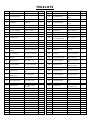
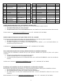
TEILELISTE
Nr.
Bezeichnung
Spezif.
Menge
Nr.
Bezeichnung
Spezif.
Menge
1
Schaumstoff (A)
Φ23 x 3 x 550
1
40
Schraube
M6 x 10 x Φ12
2
2 Tablet-Halterung 1 41 Frontabdeckung 157 x 152 x 38,5
HIPS
1
3
Griffstange (A)
1
42
Kurbelkappe
Φ25 x 7
2
4 Endkappe Φ25 x 16 2 43 Schraubenmutter M10 x 1,25 x H7,5
x S14 2
5
Schraube
M6 x 16 x S4
4
44L/R
(Siehe Teil Nr. 92 L/R)
-
6
Bolzen
M10 x 35 x 15 x H6
2
45L/R
Kurbel
170 “L/R” 9/16
2
7 Schaumstoffgriff Φ23 x 3 x 460 2 46 Abdeckung für
Mittelachse Φ50 x Φ32 x 33 1
8
Griffstange (B)
1
47
Benzingring
D17
1
9
Computer
1
48
Kugellager
6203-2RS
2
10 Lenkerstütze 1 49 Innere
Riemenabdeckung
504 x 259 x 23 1
11
Schraubenmutter
M10 x H9,5 x S17
2
50
Schraube
ST4,2 x 16 x Φ8
3
12
Schraubenmutter
M8
4
51
Riemenrad
Φ204 x 21 x 5 PK
1
13
Endkappe
F30 x 30 x 16
3
52
Mittelachse
1
14
Buchse
F38 x F30 x 153,3
3
53
Schraube
M10 x 16 x S6
4
15 Spannungssteuerung
sknopf Φ58 x 44 x M8 x 18 1 54 Riemen 5PK520 1
16 Bremsstange
Φ10 x 210 x M8 x
15 x M6 x 7 x M10 x
1 55 Schraube ST4,2 x 13 x Φ8 9
17 Buchse 20 x 20 x 65 1 56 Äußere
Riemenabdeckung 648 x 264 x 45 1
18 Beilagscheibe D6 x Φ12 x 1,2 2 57 Schraubenmutter M12 x 1 x H19,5 x
S19
2
19 Vierkantmutter 15 x 15 x 25 x M10 1 58 Trägheitsachse Φ15 x 165 x 72 x
M12 x 1 x 33,5
1
20
Schraubenmutter
M8 x H5,5 x S14
1
59
Abstandhalter
Φ22 x Φ12,5 x 6
2
21 Sprungfeder Φ2,0 x Φ15 x 54 x
N12 1 60 Einstellschraube M6 x 50 x Φ12 x 5 2
22 Dekorative
Abdeckung 195 x 161 x 31 1 61 Schraubenmutter M6 x H5 x S10 2
23
Schraubenmutter
M10 x H5,5 x S17
1
62
Schraubenmutter
M6 x H6 x S10
2
24 Schraubenmutter M6 x H11 x S10 1 63 Schraubenmutter M12 x 1 x H6 x
S19
3
25
Bremsenstopper
35 x 24 x 2
1
64
Kugellager
6202-2RS C&U
3
26 Sprungfeder Φ2 xΦ24 x Φ13 x
17 x N4 1 65 Trägheitsrad
18 x Φ460 x 75 x
30 x Φ55 x 42 x
1
27
Bremsklotz
110 x 27 x 30
1
66
Abstandhalter
Φ18 x Φ12,2 x 4
1
28
Beilagscheibe
D5 x Φ10 x 1
2
67
Induktor
1
29
Schraubenmutter
M5 x H5,5 x S10
2
68
Magnet
1
30
Schraube
M5 x 30 x Φ8
2
69
Beilagscheibe
D5 x Φ13 x 1,0
4
31
Wollfilz
110 x 30 x 10
1
70
Wasserflaschenhalter
1
32
Federelement
T2 x 59 x 185
1
71
Beilagscheibe
D5 x Φ13 x 1
2
33
Gummimatte
35 x 20 x 3
1
72
Schraube
M5 x 15 x Φ10
2
34
Bolzen
M6 x 12 x S10
2
73
Stabilisator Vorne
1
35
Sitz
98-2
1
74
Fußnivellierer
Φ43 x 14 x M8 x
4
36
Sattelschlitten
1
75
Endkappe
30*70*1,5t
4
37
Sattelstütze
1
76
Schraube
M8 x 40 x 20 x S5
6
38
Einstellknopf
M16 x 1,5
3
77
Beilagscheibe
Φ8,4 x Φ16 x 1,6
6
39
Tülle
Φ12 x 11 x Φ3
2
78
Transportrad
Φ42 x 18 x Φ8 x 22
2

8
Nr.
Bezeichnung
Spezif.
Menge
Nr.
Bezeichnung
Spezif.
Menge
79
Schraubenmutter
M8 x H7,5 x S13
2
89
Schraubenschlüssel
S10-13-17-22
1
80 Beilagscheibe D8 x Φ16 x 1,5 2 90L/R Nylonmutter
9/16 x 20 x H8 x
S22
2
81
Schraube
ST4,8 x 10 x Φ8
4
91
Stammkabel
1
82
Versandhülse Vorne
1
92L/R
Pedal
YH-102 9/16"
2
83 Schraube M5*10 1 93 Abstandhalter Φ22 x Φ15,1 x
39,1
1
84
Stabilisator Hhinten
1
94
Abstandhalter
Φ22 x Φ17,1 x 5,5
1
85
Hauptrahmen
1
95
Wellenscheibe
Φ17,5 x Φ23 x 0,3
1
86 Abstandhalter Φ21,8 x Φ12,2 x
11,5 1 96 Abstandhalter Φ22 x Φ17,1 x 10 1
87 Inbusschlüssel S5-S6 1 97 Schraube M8 x 15 2
88
Schraubenschlüssel
S13-14-15
1
98
Hintere Versandhülse
1
Ordering Replacement Parts (U.S. and Canadian Customers only)
Please provide the following information in order for us to accurately identify the part(s) needed:
The model number (found on cover of manual)
The product name (found on cover of manual)
The part number found on the “EXPLODED DIAGRAM” and “PARTS LIST” (found near the front of the manual)
Please contact us at support@sunnyhealthfitness.com or 1- 877 - 90SUNNY (877-907-8669).
Pedido de piezas de repuesto (solo para clientes de EE. UU. y Canadá)
Proporcione la siguiente información para que podamos identificar con precisión las piezas necesarias:
El número de modelo (se encuentra en la portada del manual).
El nombre del producto (se encuentra en la portada del manual).
El número de pieza que se encuentra en el “ESQUEMA DE LAS PIEZAS” y en la “LISTA DE PIEZAS” (se
encuentra al principio del manual).
Contáctenos en support@sunnyhealthfitness.com o 1- 877 - 90SUNNY (877-907-8669).
Pour commander des pièces de rechange (clients américains et canadiens seulement)
Veuillez fournir les informations suivantes afin que nous puissions identifier avec précision la pièce ou les pièces
requise(s):
Le numéro de modèle (situé sur la couverture du manuel)
Le nom du produit (situé sur la couverture du manuel)
Le numéro de pièce figurant sur le «SCHÉMA ÉCLATÉ» et la «LISTE DES ÉLÉMENTS» (situé vers le début du
manuel)
Veuillez nous contacter à support@sunnyhealthfitness.com ou 1- 877 - 90SUNNY (877-907-8669).
Bestellung von Ersatzteilen (nur für US-amerikanische und kanadische Kunden)
Bitte geben Sie die folgenden Informationen an, damit wir das/die benötigte(n) Teil(e) genau identifizieren können:
Die Modellnummer (finden Sie auf dem Umschlag der Anleitung)
Die Produktbezeichnung (finden Sie auf dem Umschlag der Anleitung)
Die Teilenummer auf der „EXPLOSIONSDARSTELLUNG“ und der „TEILELISTE“ (finden Sie vorne in der
Anleitung)
Bitte kontaktieren Sie uns unter support@sunnyhealthfitness.com oder 1- 877 - 90SUNNY (877-907-8669).

9
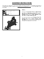
ASSEMBLY INSTRUCTIONS
We value your experience using Sunny Health and Fitness products. For assistance with parts or
troubleshooting, please contact us at support@sunnyhealthfitness.com or 1-877-90SUNNY (877-
907-8669).
77
97
97
77
#77 Φ8.4*Φ16*1.6 2PCS
#97 M8*15 2PCS
#87 S5-S6
85
98
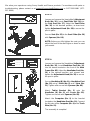
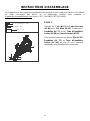
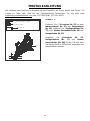
STEP 1:
Unscrew 2 Screws (No. 97) from Main Frame
(No. 85) with Allen Wrench (No. 87), remove 2
Washers (No. 77) and Rear
Shipping Tube
(No. 98) from Main Frame (No. 85).
You may save these parts [Screws (No. 97),
Washers (No. 77), and Rear Shipping Tube
(No. 98)] in case you would like to repackage and
transport this equipment in the future.

10
We value your experience using Sunny Health and Fitness products. For assistance with parts or
troubleshooting, please contact us at support@sunnyhealthfitness.com or 1-877-90SUNNY (877-
907-8669).
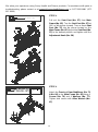
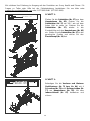
38
85
37
#38 M16*1.5 1PC
38
85
37
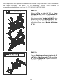
STEP 2:
Pull out the Seat Post (No. 37) from Main
Frame (No. 85). Turn the Seat Post (No. 37) at
180° as left picture showed. Then re-insert Seat
Post (No. 37) into the sleeve located on the
Main Frame (No. 85). Adjust the Seat Post (No.
37) to the desired position and tighten with the
Adjustment Knob (No. 38).
STEP 3:
Attach the Front and Rear Stabilizers (No. 73
& No. 84) to the Main Frame (No. 85) using 4
Screws (No. 76) and 4 Washers (No. 77).
Tighten and secure with Allen Wrench (No.
87).

11
We value your experience using Sunny Health and Fitness products. For assistance with parts or
troubleshooting, please contact us at support@sunnyhealthfitness.com or 1-877-90SUNNY (877-
907-8669).
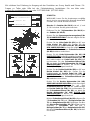
15
85
70
71
72
71
92R
45R
90R
92L
45L
90L
92L
45L
S15
88
S15
88
S22 89
88
88
45R
92R
89 S22
S15
#89 S22
S15
#88
#90L/R 9/16*20*H8*S22 2PCS
#71 D5*φ13*1 2PCS
#72 M5*15*φ10 2PCS
92L
90L 90R
92R
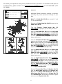
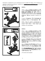
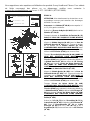
STEP 4:
WARNING! Read instructions carefully as improper
assembly may cause permanent damage to your
bike.
Note: The Pedals (No. 92L/R) are marked "L" and
"R" for Left and Right.
Remove the 2 Nylon Nuts (No. 90L/R) located on the
Pedals (No. 92L/R).
Turn the Tension Control Knob (No. 15)
CLOCKWISE as tightly as you can with your hand.
Align the Left Pedal (No. 92L) with the Left Crank
(No. 45L) at 90°. Turn the pedal bolt on the Left Pedal
(No. 92L) COUNTER-CLOCKWISE as tightly as you
can with your hand. Then, use Spanner (No. 88) to
tighten and secure.
Turn the Left Nylon Nut (No. 90L) CLOCKWISE as
tightly as you can with your hand. Use Spanner (No.
88) to hold the pedal bolt on the Left Pedal (No. 92L)
and use Spanner (No. 89) to turn the Left Nylon Nut
(No. 90L) CLOCKWISE at the same time, until it is
tightened on to the Left Crank (No. 45L).
Align the Right Pedal (No. 92R) with the Right Crank
(No. 45R) at 90°. Turn the pedal bolt on the Right
Pedal (No. 92R) CLOCKWISE as tightly as you can
with your hand. Then, use Spanner (No. 88) to
tighten and secure.
Turn the Right Nylon Nut (No. 90R) COUNTER-
CLOCKWISE as tightly as you can with your hand.
Use Spanner (No. 88) to hold the pedal bolt on the
Right Pedal (No. 92R) and use Spanner (No. 89) to
turn the Right Nylon Nut (No. 90R) COUNTER-
CLOCKWISE at the same time, until it is tightened on
to the Right Crank (No. 45R).
Remove 2 Screws (No. 72) and 2 Washers (No. 71)
from the Main Frame (No. 85) using Spanner (No.
88). Attach the Water Bottle Holder (No. 70) to the
Main Frame (No. 85) using the 2 Screws (No. 72)
and 2 Washers (No. 71) that were removed. Tighten
and secure with Spanner (No. 88).

12
We value your experience using Sunny Health and Fitness products. For assistance with parts or
troubleshooting, please contact us at support@sunnyhealthfitness.com or 1-877-90SUNNY (877-
907-8669).
38
37
S14
#88
35
36
83
91
85
38
#83 M5*10 1PC
#6 M10*35*15*H6 2PCS
#11 M10*H9.5*S17 2PCS
S17
#89
#88
11
9
6
2
8
9
91 10
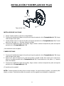
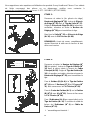
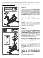
STEP 6:
Loosen and remove the [handlebar] Adjustment
Knob (No. 38). Insert Handlebar Post (No. 10)
into the sleeve located on the front of the Main
Frame (No. 85). Adjust the Handlebar Post (No.
10)
to the desired position and reinsert and
tighten the Adjustment Knob (No. 38) to secure
the post in place.
Secure Handlebar (B) (No. 8) to Handlebar Post
(No. 10) using 2 Bolts (No. 6) and 2 Nuts (No.
11). Tighten and secure with Spanner (No. 89).
Attach Tablet Bracket (No. 2) onto the
Handlebar (B) (No. 8) with Screw (No. 83).
Tighten and secure with Spanner (No. 88).
Attach the Computer (No. 9)
to the bracket
located on the Handlebar Post (No. 10). Connect
the link wire of the Computer (No. 9) to the Trunk
Wire (No. 91).
The assembly is complete!
STEP 5:
Loosen and remove the [seat slider] Adjustment
Knob (No. 38). Insert Seat Slider (No. 36) into
the Seat Post (No. 37). Adjust the Seat Slider
(No. 36) to the desired position, re-insert and
tighten Adjustment Knob (No. 38) to secure the
post in place.
Secure Seat (No. 35) to the Seat Slider (No. 36)
with Spanner (No. 88).
NOTE: Before you fully tighten the seat, you can
adjust the front of the seat higher or lower to meet
your needs.

13
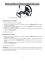
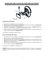
BATTERY INSTALLATION & REPLACEMENT
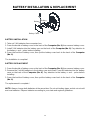
BATTERY INSTALLATION
1. Take out 2 AA batteries from computer box.
2. Press the buckle of battery cover on the back of the Computer (No. 9), then remove battery cover.
3. Install 2 AA batteries into the battery case on the back of the Computer (No. 9). Pay attention to
the battery + and – poles before installing.
4. Press the buckle of battery cover, then put the battery cover back to the back of the Computer
(No. 9).
The installation is complete!
BATTERY REPLACEMENT
1. Press the buckle of battery cover on the back of the Computer (No. 9), then remove battery cover.
2. Remove the 2 old AA batteries in the battery case and install 2 new AA batteries into the battery
case on the back of the Computer (No. 9). Pay attention to the battery + and – poles before
installing.
3. Press the buckle of battery cover, then put the battery cover back to the back of the Computer
(No. 9).
The replacement is complete!
NOTE: Always change both batteries at the same time. Do not mix battery types and do not mix old
and new batteries. Dispose batteries according to your state and regional guidelines.
9
Battery
Battery
Battery Cover

14
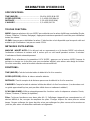
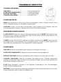
EXERCISE COMPUTER
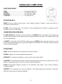
SPECIFICATIONS:
TIME-------------------------------------------00:00-99:59 MIN:SEC
SPEED----------------------------------------0.0-999.9 MI (Mile)/H
DISTANCE-----------------------------------0.00-99.99 MI (Mile)
CALORIES-----------------------------------0.0-999.9 KCAL
FUNCTION KEY:
MODE: Press to select function (Scan, Time, Speed, Distance, Calories). Press and hold for 3
seconds to reset all values.
CLEAR: Press to reset value. This function is only available when the bike is stopped, and the
computer is not in SCAN mode.
OPERATION PROCEDURES:
1. AUTO ON/OFF: If the bike is put into motion or the MODE button is pressed, the computer will
activate and will remain active unless inactive for approximately 4 minutes. The computer power will
turn off automatically.
2. MODE: To select the LOCK MODE setting, press the MODE button when the pointer is on the
function you wish to display, then remove your finger from the button. Once locked, only the selected
function will be displayed.
FUNCTIONS:
TIME: Counts the total time of an exercise from start to finish.
SPEED: Displays the current speed being obtained.
DISTANCE: Counts the total distance of an exercise from start to finish.
CALORIES: Counts the total number of calories burned during an exercise from start to finish. (The
data is a rough guide which can not be used in medical treatment.)
SCAN: Automatically displays functions in the following order shown: Time, Speed, Distance,
Calories (repeat).
BATTERY: This computer uses two AA batteries. If the display appears incorrectly or becomes
difficult to read, please install new batteries.

15
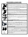
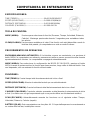
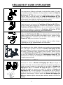
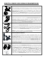
ADJUSTMENTS & USAGE GUIDE
74
ADJUSTING THE BALANCE
In order to achieve a smooth and comfortable ride, you must ensure that the
bike is stabled and
secured. If you notice that the bike is unbalanced during
use, you should adjust the Foot Levelers (No. 74) located beneath the front
and rear stabilizers. To do so, simply rotate the Foot Leveler (No. 74) until
the bike becomes level with the floor surface.
If required, repeat this process
to adjust the remaining Foot Levelers (No. 74).
15
ADJUSTING THE TENSION & EMERGENCY STOP
Adjust the tension by rotating the Tension Control Knob (No. 15) clockwise
to increase the level of resistance. Rotate the Tension Control Knob (No.
15) counter-clockwise
to decrease the level of resistance. Push down on the
Tension Control Knob (No. 15)
to enforce the brake and stop the bike
immediately.
ADJUSTING THE ANGLE OF SEAT
Use Spanner (No. 88)
to unscrew the nut under the seat. Adjust the seat to
the desired angle and reinstall the nut. Check the nut periodically to ensure
that it is tight and secure. Use the Spanner (No. 88)
to tighten when
necessary.
Note: You will need to tighten the nut on
the opposite side at the same time.
The use of an additional spanner is required.
MOVING THE BIKE
To move the bike, first ensure that the handlebar is properly secured. If the
handlebar is loose, tighten the Adjustment Knob (No. 38) to secure it. Next,
stand at the front of the bike so that you’re directly in front of the handlebar.
Firmly grasp and hold each side of the handlebar, place one foot on the
Front Stabilizer (No. 73)
, and tilt the bike towards you until the
transportation wheels on the Front Stabilizer (No. 73)
touches the ground.
With the transportation
wheels on the ground, you can transport the bike to
the desired location with ease.
III
38 3838 38
36
36
ADJUSTING THE HEIGHT
Loosen and pull out the Adjustment Knob (No. 38)
to adjust the height of
the seat. You may also slide the seat forward or backwards by loosening and
pulling out the Adjustment Knob (No. 38) on the Seat Slider (No. 36). You
may adjust the height of the handlebar by using the Adjustment Knob (No.
38)
. When adjusting, you will see a limit on the seat post, seat slider, and
handlebar post. Do not
lift the posts passed this mark. Always check the
Adjustment Knob (No. 38) to ensure that it is fully secured when you finish
making an adjustment.
S
14
#88

16
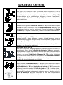
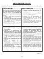
MAINTENANCE INSTRUCTIONS
This is general information for daily, weekly, and monthly maintenance to be performed on your bike.
DAILY MAINTENANCE
After each exercise session, wipe down all the
equipment: seat, frame, and
handlebars. Pay
special attention to the seat post, handlebar
post, and belt/chain guard. Sweat is very
corrosive and may cause problems that require
parts replacement later.
1. Get on the bike and engage the drive train.
2. Pay attention to any vibrations felt through
the pedals. If you feel any vibrations, you
may need to tighten the pedals, bottom
bracket, or adjust the drive belt/chain
tension.
3.
Use a wrench to tighten the pedals until they
are secure.
MONTHLY MAINTENANCE
1. Check if all hardware is secure, such as: water
bottle holder, flywheel nuts, belt/chain guard
bolts, brake caliper lock nuts, and brake caliper
tension rod nuts.
2.
Inspect the brake tension rod for signs of wear
such as missing threads. Clean and lubricate
the brake tension rod.
3. Clean and
lubricate the seat post, handlebar
post and seat slider. Remove any builtup of
foreign material.
WEEKLY MAINTENANCE
1.
Inspect moving parts and tighten the
hardware.
2.
Inspect pull pin frame fittings to make sure
the fittings are secure. Loose frame fittings
may strip out threads over time and cause
extensive damage.
3.
Clean and lubricate pop pin assemblies. Pull
on the pin and spray a small amount of
lubricant onto the shaft.
4.
Tighten the seat hardware to make sure the
seat is level and centered.
5. Brush
and treat the resistance pads.
Remove any foreign material that may have
collected on the pads. Spray the pads with
silicone lubricant. This helps to reduce noise
from friction between the pads and the
flywheel.
6. Visually inspect the bottom bracket, toe clips
and toe straps. If any of them are loose or
disconnected, attach and tighten.
LEATHER BRAKE PAD CARE (If applicable)
1.
Perform this maintenance when the brake pad
is first installed and for the life of the brake pad.
Following these simple guidelines can increase
the life of your brake pads.
2. Some brake pad assemblies are pre-lubricated.
Squeeze the brake pad. If lubricant is released,
then the pad has been pre-lubricated.
3.
If the brake pad is dry, then coat the brake pad
with 3-n-1 oil. Brush the leather
with a clean,
wire bristle brush, and then apply the oil. The oil
should be allowed to soak in to the pad. Repeat
4-
5 times until the pad is saturated, but not
dripping with oil. When the pad is saturated, it
will no longer absorb oil.
4. Inspect the brake p
ad weekly and lubricate if
needed. The pad should not have a glazed
appearance. If the pad appears glazed, then
brush it with wire brush and apply lubricant as
needed. If any of the sponge padding is
showing through the leather pad, the brake pad
should be replaced.
Version: 5.2

17
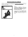
INSTRUCCIONES DE ARMADO
Valoramos su experiencia con los productos de Sunny Health and Fitness. Para asistencia con
repuestos o solución de problemas, contáctenos en support@sunnyhealthfitness.com o al 1-877-
90SUNNY (877-907-8669).
77
97
97
77
#77 Φ8.4*Φ16*1.6 2PCS
#97 M8*15 2PCS
#87 S5-S6
85
98
PASO 1:
Desatornille 2 Tornillos (n.° 97)
de la
Estructura Principal (n.° 85) con la Llave Allen
(n.° 87). Retire las 2 Arandelas (n.° 77) y los 1
Tubo de Envío Trasero (n.° 98)
de la
Estructura Principal (n.° 85).
Puede guardar estas piezas [Tornillos (n.º 97),
Arandelas (n.° 77) y Tubo de Envío Trasero
(n.° 98)]
en caso de que desee volver a
empaquetar y transportar este equipo en el
futuro.

18
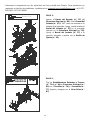
Valoramos su experiencia con los productos de Sunny Health and Fitness. Para asistencia con
repuestos o solución de problemas, contáctenos en support@sunnyhealthfitness.com o al 1-877-
90SUNNY (877-907-8669).
38
85
37
#38 M16*1.5 1PC
38
85
37
PASO 2:
Agarre el Barral del Asiento (n.° 37) del
Estructura Principal (n.° 85). Gire el Barral del
Asiento (n.° 37) a 180° como se muestra en la
imagen de la izquierda. Luego, vuelva insertar el
Barral del Asiento (n.° 37)
en el manguito
ubicado en la Estructura Principal (n.° 85).
Ajuste el Barral del Asiento (n.° 37)
a la
posición deseada y apriete con la Perilla de
Ajuste (n.° 38).
PASO 3:
Fije los Estabilizadores Delantero y Trasero
(n.° 73 & n.° 84) al Estructura Principal (n.°
85) con 4 Tornillos (n.° 76) y 4 Arandelas (n.°
77). Apriete y asegura con la Llave Allen (n.°
87).

19
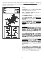
Valoramos su experiencia con los productos de Sunny Health and Fitness. Para asistencia con
repuestos o solución de problemas, contáctenos en support@sunnyhealthfitness.com o al 1-877-
90SUNNY (877-907-8669).
15
85
70
71
72
71
92R
45R
90R
92L
45L
90L
92L
45L
S15
88
S15
88
S22 89
88
88
45R
92R
89 S22
S15
#89 S22
S15
#88
#90L/R 9/16*20*H8*S22 2PCS
#71 D5*φ13*1 2PCS
#72 M5*15*φ10 2PCS
92L
90L 90R
92R
PASO 4:
¡ADVERTENCIA! Lea las instrucciones
detenidamente, ya que un armado incorrecto puede
causar daños permanentes a su bicicleta.
Nota: Los Pedales (n.° 92L/R) están marcados “L” y
“R” para izquierda y derecha.
Retire las 2 Tuercas de Nailon (n.° 90L/R) ubicadas
en los Pedales (n.° 92L/R)
Gire la Perilla de Tensión (n.° 15)
HACIA A LA
DERECHA tan fuerte como puede con su mano.
Alinee el Pedal Izquierdo (n.° 92L) con la Brazo de la
Manivela Izquierda (n.° 45L) a 90°. Gire el perno del
pedal en el Pedal Izquierdo (n.° 92L) HACIA A LA
IZQUIERDA tan fuerte como puede con su mano.
Luego, use la Llave Inglesa (n.° 88) para apretar y
asegurar.
Gire la Tuerca de Nailon Izquierda (n.° 90L) HACIA A
LA DERECHA tan fuerte como pueda con su mano.
Use la Llave Inglesa (n.° 88) para sostener el perno
del pedal en el Pedal Izquierdo (n.° 92L) y use la Llave
Inglesa (n.° 89) para girar la Tuerca de Nailon
Izquierda (n.° 90L) HACIA A LA DERECHA al mismo
tiempo, hasta que esté apretada a la Brazo de la
Manivela Izquierda (n.° 45L).
Alinee el Pedal Derecho (n.° 92R) con la Brazo de la
Manivela Derecha (n.° 45R) a 90 °. Gire el perno del
pedal en el Pedal Derecho (n.° 92R) HACIA A LA
DERECHA tan fuerte como pueda con la mano. Luego,
use la Llave Inglesa (n.° 88) para apretar y asegurar.
Gire la Tuerca de Nailon Derecha (n.° 90R) HACIA A
LA IZQUIERDA con la mano. Use la Llave Inglesa (n.°
88) para sostener el perno del pedal en el Pedal
Derecho (n.° 92R) y use la Llave Inglesa (n.° 89) para
girar la Tuerca de Nailon Derecha (n.° 90R) HACIA A
LA IZQUIERDA
al mismo tiempo, hasta que está
apretado en la Brazo de la Manivela Derecha (n.°
45R).
Retire 2 Tornillos (n.° 72) y 2 Arandelas (n.° 71) del
Estructura Principal (n.° 85) usando la Llave Inglesa
(n.° 88). Fije el Soporte para Botella (n.° 70) al
Estructura Principal (n.° 85) utilizando los 2 Tornillos
(n.° 72) y las 2 Arandelas (n.° 71) que se quitaron.
Apriete y asegure con la Llave Inglesa (n.° 88).
Seite wird geladen ...
Seite wird geladen ...
Seite wird geladen ...
Seite wird geladen ...
Seite wird geladen ...
Seite wird geladen ...
Seite wird geladen ...
Seite wird geladen ...
Seite wird geladen ...
Seite wird geladen ...
Seite wird geladen ...
Seite wird geladen ...
Seite wird geladen ...
Seite wird geladen ...
Seite wird geladen ...
Seite wird geladen ...
Seite wird geladen ...
Seite wird geladen ...
Seite wird geladen ...
Seite wird geladen ...
Seite wird geladen ...
Seite wird geladen ...
-
 1
1
-
 2
2
-
 3
3
-
 4
4
-
 5
5
-
 6
6
-
 7
7
-
 8
8
-
 9
9
-
 10
10
-
 11
11
-
 12
12
-
 13
13
-
 14
14
-
 15
15
-
 16
16
-
 17
17
-
 18
18
-
 19
19
-
 20
20
-
 21
21
-
 22
22
-
 23
23
-
 24
24
-
 25
25
-
 26
26
-
 27
27
-
 28
28
-
 29
29
-
 30
30
-
 31
31
-
 32
32
-
 33
33
-
 34
34
-
 35
35
-
 36
36
-
 37
37
-
 38
38
-
 39
39
-
 40
40
-
 41
41
-
 42
42


Sunny SF-B1423 Benutzerhandbuch
- Kategorie
- Spinbikes
- Typ
- Benutzerhandbuch
in anderen Sprachen
- français: Sunny SF-B1423 Manuel utilisateur
- español: Sunny SF-B1423 Manual de usuario
Verwandte Artikel
Andere Dokumente
-
 Sunny Health & Fitness SF-B1423 Benutzerhandbuch
-
 SUNNY Health Fitness SF-RW5856 Benutzerhandbuch
-
SUNNY Health Fitness SF-B0891 Benutzerhandbuch
-
SUNNY Health Fitness SF-RW5515 Benutzerhandbuch
-
 SUNNY Health Fitness P2100 Benutzerhandbuch
-
 SUNNY Health Fitness SF-RB4905 MAGNETIC RECUMBENT EXERCISE BIKE Benutzerhandbuch
-
 SUNNY Health Fitness SF-E3890 Benutzerhandbuch
-
SUNNY Health Fitness SF-A020052 Benutzerhandbuch
-
SUNNY Health Fitness SF-RB4616 Benutzerhandbuch
-
AsVIVA H22 Bedienungsanleitung


