Pfaff Tipmatic 1119 Bedienungsanleitung
- Kategorie
- Nähmaschinen
- Typ
- Bedienungsanleitung
Dieses Handbuch eignet sich auch für

tipmatic
1119
Bedienungsanleitung
Instruction
Book
Mode
d’emploi
Libretto
istruzioni

Diese
Seite
nach
auen
kiappen
Foki
out
this
page
Rabattre
ce
volet
vers
I’extérieur
Girare
questa
pagina
verso
I’esterno
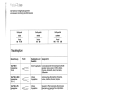
Sicherheitshinweise
für
Haushaltnähmaschinen
nach
DIN
57
700
Tell
28
bzw.
IEC
335
Teil
28
a)
Der
Benutzer
hat
wegen
der
auf-
und
abgehenden
Nadel
genugend
Vorsicht
walten
zu
lassen
und
die
Nähstelle
bei
der
Arbeit
ständig
zu
beobachten.
b)
Beim
Verlassen
der
Maschine,
bei
Wartungsarbeiten
oder
beim
Wech
sein
von
mechanischen
Teilen
oder
Zubehör
ist
die
Maschine durch
Her
ausziehen
des
Netzsteckers aus der
Steckdose
vom
Netz
zu
trennen.
C)
Die
maximal
zulässige
Leistung
der
Lampe
beträgt
15
Watt.
Some
safety
rules
a)
Take
care
to
avoid
injury
to
your
fin
gers
by
the
needle
during
sewing.
b)
Be
sure
to
unplug
the
power
cord
whenever
you
leave
the
machine
or
wish
to
clean
it,
oil
it
or
change
mechanical
and
accessory
parts.
c)
Be
sure
to
use
only
a
15-watt
light
bulb
in
the
sewing
lamp.
d)
The
drive
belt
must
never
be
adjusted
by
anyone
but
an
authorized
Pfaff
agent.
For
safety
rules
applicable
to
the
UK
please
see
page
84.
C:
Mesures
de
sécurité
a)
Toujours
faire
preuve
de
prudence
et
continuellement
surveilier
le
travail.
b)
Toujours
débrancher
Ia
machine
du
secteur
avant
de
quitter
Ia
machine,
avant
les
travaux
d’entretien
et
en
cas
de
remplacement
de
pièces
mécani
ques
ou
d’accessoires.
c)
Puissance
maximale
admissible
de
l’ampoule:
15
Watts.
Norme
di
sicurezza
per
macchine
per
cucire
per
uso
famiglia
secondo
DIN
57
700
parte
28
oppure
IEC
335
parte
28
a)
In
virtü
del
movImento
alternativo
dell’ago,
l’utente
deve
prestare
suffi
ciente
attenzione
e
tenere
costante
mente
d’occhio
ii
punto
di
lavoro.
b)
Nel
cambiare
ago,
piedino,
spolina
e
placca
d’ago,
nelle
interruzioni
non
custodite
del
lavoro
e
durante
i
lavori
di
manutenzione
si
deve
disinserire
Ia
corrente
della
macchina
togliendo
Ia
spina
dalla
presa
a
muro.
c)
La
potenza
massima
consentita
per
Ia
lampadina
è
di
15
Watt.
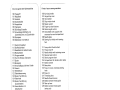
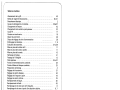
Inhaltsverzeichnis
Contents
on
page
Seite
61
63)
sable
des
mati&es,
pane
klndice
pagina
65
67)
Seite wird geladen ...

1
I
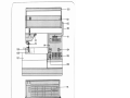
Becenungsteile
der
Na
hmaschine
100
Tragegriff
101
Klappdeckel
102
Handrad
103
Auslösescheibe
104
Hauptschalter
105
Tipptasten
106
Stichlangen-Einsteller
107
Verwandlungs-Nähfläche
mit
Zubehörkästchen
und
Zubehörfach
108
Stichplatte
109
Nähfu1haIter
mit
Nähful3,
111
Zierstich-Einstellrad
11
2
Stoffdrückerhebel
11
3
Nadelhalter
mit
Halteschraube
11
4
Rückwärtstaste
11
5
Programmtabelle
11
6
Fach
für
Bordüren-Ubersicht
117
Spuler
11
8
Bodenplatte
11
9
VerschIufklappe,
dahinter
Greifer
120
Freiarm
121
Einfädelschlitz
122
Oberfadenspannung
123
Spuler-Fadenfuhrung
124
Fadenhebel
125
Spuler-Fadenführung
(ausschwenken)
126
Garnrollenhalter
mit
Ablaufscheibe
127
Zweiter
Garnrollenhalter
(hochschwenken)
1
28
Stoffdruckerstange
mit
Fadenabschneider
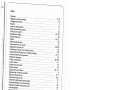
Parts
of
your
sewing
machine
100
Carrying
handle
101
Hinged
top
cover
1
02
Hand
wheel
103
Stop
motion
knob
1
04
Master
switch
1
05
Finger-tip
stitch
buttons
1
06
Stitch
length
control
1
07
Detachable
work
support
with
accessory
box
and
compartment
108
Needle
plate
1
09
Sewing
foot
holder
with
sewing
foot
111
Fancy-stitch
thumb
wheel
112
Presser
bar
lift
11
3
Needle
holder
with
retaining
screw
11
4
Reverse-feed
control
11
5
Stitch
program
chart
11
6
Compartment
for
border-stitch
table
11
7
Bobbin
winder
11
8
Base
plate
11
9
Free
arm
cover
enclosing
sewing
hook
1
20
Free
arm
121
Threading
slots
1
22
Needle
thread
tension
1
23
Bobbin
winder
thread
guide
1
24
Take-up
lever
1
25
Bobbin
winder
thread
guide
(swing-out)
1
26
Spool
holder
with
unreeling
disc
1
27
Sewing
spool
holder
(swing
up)
1
28
Presser
bar
with
thread
cutter
Seite wird geladen ...
Seite wird geladen ...
Seite wird geladen ...
Seite wird geladen ...
Seite wird geladen ...

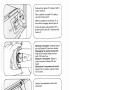
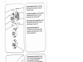
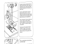
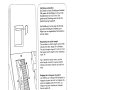
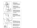
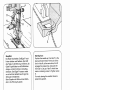
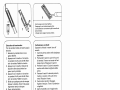
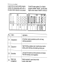
Spulen
von
einer
zweiten
Garnrolle:
Spulerfadenführung
125
nach
vorn
schwenken.
Den
Faden
in
die
Führung
123
und, wie
die
Zeichnung
zeigt,
in
die
Fuhrung
125
ziehen,
wobei
der
Faden
zwischen
die
Führung
und
die
Span
nungsfeder
N
kommen
rnul.
Nun
den
Faden
einige
Male
urn
die
Spule
wickein.
Die
Spule
nach
rechts
drücken.
Den
Anlasser
betätigen
und
aufspuien.
Die
voile
Spule
nach
links
drücken,
abneh
rnen,
den
Faden
nach
vorn
ziehen
und
irn
Abschneider
0
durchschneiden.
Wichtig:
Bei
Garnrollen
rnit
Fadenhalte
schlitz
rnu1
der
Schlitz
beirn
Aufschieben
rechts
sein.
Winding
the
bobbin
from
a
second
spool:
tilt
spool
pin
1
25
forward.
Pull
the
thread
into
guide
1
23
and
into
guide
1
25
as
shown
in
the
drawing,
rnaking
sure
that
the
thread
passes
between
the
guide
and
tension
spring
N.
Now
wind
the
thread
a
few
turns
around
the
bobbin.
Push
the
bobbin
to
the
right.
Press
the
foot
control
to
wind
the
bobbin.
Push
the
filled
bobbin
to
the
left,
rernove
it,
pull
the
thread
to
the
front
and
cut
it
in
thread
cutter
0.
Important
note:
On
spools
with
thread
retaining
slots
the
slot
must
face
right
when
the
spool
is
fitted.
4
6
Seite wird geladen ...

i1ili
I;j
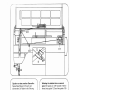
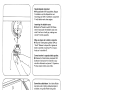
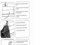
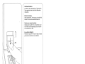
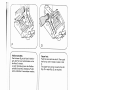
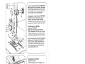
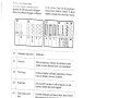
Winding
through
the
needle
eye
(0)
Raise
the
sewing
foot.
The
needle
must
be
in
its
‘up’
position.
Place
a
bobbin
on
spindle
117.
Disengage
the
sewing
mechanism.
Draw
the
needle
thread
under
the
sewing
foot,
up
and
into
guide
125
(see
drawing.
Wind
the
thread
around
the
bobbin
a
few
times
and
push
the
bobbin
toward
the
right>.
Press
the
foot
control
pedal
and
wind
the
bobbin.
Push
the
full
bobbin
toward
the
left
and
take
it
out.
Cut
the
thread
in
thread
cutter
l\j
ft.
7—.-
-fi
U
ii
ii
H__IL__1E
1
_L
/?25-
-F
117
/
1-
‘ni-i
4
Spulen
durch
die
Nadel:
Den
Nähfu1
anheben.
Nadelstellung
oben.
Die
Spule
auf
den
Spuler
117
aufstecken.
Nähwerk
ausschalten.
Den
Oberfaden
unter
dem
Nähfu1
nach
rechts
und
durch
die
Führung
125
ziehen
(siehe
Zeichnung).
Den
Faden
einige
Male
urn
die
Spule
wickeln
und
diese
nach
rechts
drücken.
Den
Anlasser
betätigen
und
aufspulen.
Die
voile
Spule
nach
links
drücken,
abnehmen,
den
Faden
nach
vorn
ziehen
und.
irn
Abschneider
“N”
durchschneiden.
8
Seite wird geladen ...
Seite wird geladen ...

4
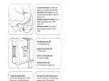
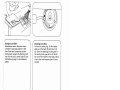
Spulenkapsel
einsetzen:
•
Hauptscha/ter
104
ausschalten.
Kiappe
N
anheben
und
die
Kapsel
bis
zum
Ansch
lag
auf
Stift
0
schieben.
Ausschnitt
P
mu1
dabei
nach
oben
zeigen.
Inserting
the
bobbin
case:
•
Switch
off
master
switch
104.
Raise
latch
N
and
push
the
bobbin
case
onto
stud
0
as
far
as
it
will
go,
making
sure
cutout
P
points
upwards.
Mise
en
place
de
Ia
bolte
a
canette:
•
Tourner
/‘interrupteur
généra/
104
sur
‘Arrêt’
Relever
le
loquet
N
et
glisser
Ia
boIte
a
canette,
l’ouverture
P
en
haut,
a
fond
sur
le
tourillon
0.
Come inserire
Ia
capsula
della
spolina:
•
Disinserire
I’interruttore
princIpale
104.
Sollevare
il
chiusino
N
e
inserire
Ia
cap
sula
fino
all’arresto
sul
perno
0.
L’apertura
P
deve
essere
rivolta
verso
I’alto.
j
r
N
Garnrolle
aufschieben:
Vor
kleine
Rollen
die
kleine
oder
mittlere
Ablaufscheibe
0
schieben,
vor
groRe
Rollen
die
groRe
Ablaufscheibe
R.
Placing
spool
of
thread
on
pin:
Place
the
small
or
medium-size
unwinding
col
lar
0
in
front
of
small
spools,
and
the
large
unreeling
disc
R
in
front
of
large
spools.
Mise
en
place
de
Ia
bobine
de
fil:
Utili
ser
le
dérouleur
0
(petit
diamètre)
devant
les
petites
bobines
et
le
grand
dérouleur
R
devant
les
grosses
bobines.
lnserimento
del
rocchetto
del
fib:
Davanti
a
piccoli
rocchetti
porre
il
disco
di
scorrimento
piccolo
o
medio
0,
davanti
a
grandi
rocchetti
porre
il
disco
di
scorn
mento
grande
R.
/
------
-
ii
Seite wird geladen ...
Seite wird geladen ...
Seite wird geladen ...

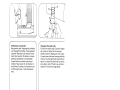
4
Fadenspannung
uberprufen:
Die
normale
Linsteliung
liegt
im
wei1en
Bereich
von
3-5.
Je
häher
die
Zahi,
je
fester
die
Spannung.
Die
Uberprüfung
wird
mit
dem
Zickzack
stich
vorgenommen.
Eine
kurze
Naht
nähen.
Die
Fadenver
knotung
soil
in
der
Mitte
der
Stoffiagen
liegen.
Checking
the
needle
thread
tension:
The
normal
setting
is
in
the
white
range
between
3
and
5.
The
higher
the
number,
the
tighter
the
tension.
To
check
the
tension,
set
the
machine
at
the
zigzag
stitch.
Sew
a
short
seam.
The
threads
should
interlock
in
the
middle
of
the
material.
Anlasser
niedertreten.
Je
tiefer
man
drückt,
um
so
schneller
näht
die
Pfaff.
Operating
the
foot
control:
The
more
you
press
down
the
pedal,
the
faster
the
machine
runs.
Abaisser
Ia
pédale
du
rheostat.
Pius
Ia
pédale
sera
abaissée,
plus
Ia
Pfaff>
coudra
vite.
Premere
ii
reostato:
Piü
a
fondo
si
preme
ii
pedale,
piü
veloce
cucirà
Ia
Pfaff”.
4
Oberfadenspannung
122
N
=
EinsteIlmarkierung.
Needle
thread
tension
122
N
=
Setting
mark.
Tension
du
fil
d’aiguille
122
N
repère
de
régiage.
Tensione
superiore
122
N
=
marcatura
per
Ia
regolazione.
/
4
16
Seite wird geladen ...

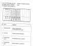
7
/
Die
Abbildung
0
unten
zeigt
die
Einstel
lung
des
Stichlàngen-Einstellers
zum
Nähen
der
rot
abgebildeten
Stretchstiche
auf
den
Tasten.
Regulating
the
stitch
length
The
numbers
on
stitch
length
control
106
indicate
the
stitch
length
in
millimeters.
The
stitch
length
range
is
0
to
6
mm.
Turn
the
desired
stitch
length
to
the
indicating
mark
“N”.
Fig.
0
(bottom)
shows
how
to
set
the
stitch
length
control
for
sewing
stretch
stitches
(red
stitch
symbols
on
push
but
tons).
Réglage
de
Ia
Iongueur
du
point:
Les
chiffres
sur
le
disque
106
indiquent
Ia
longueur
du
point
en
mm.
La
longueur
du
point
est
réglable
entre
0
et
6
mm.
La
longueur
de
point
choisie
est
indiquee
face
au
repère
N.
Lillustration
0
(en
bas)
montre
le
reglage
du
règle-point
pour
Ia
couture
des
points
élastiques
marques
en
rouge
sur
les
tou
ches.
Regolazione
della
lunghezza
del
punto:
I
numeri
sul
bottone
regolatore
della
lun
ghezza
del
punto
106
corrispondono
alla
lunghezza
del
punto
in
mm.
La
regola
zione
si
estende
da
0
a
6
mm.
La
lun
ghezza
del
punto
desiderata
si
regola
sulla
marcatura
N.
La
figura
0
sotto
mostra
Ia
regolazione
del
bottone
regolatore
per
cucire
i
punti
flexi
(stretch)
raffigurati
in
rosso
sui
tasti.
Stichlange
einstellen:
Die
Zahlen
auf
dem
Stichlängen-Einsteller
106
geben
die
Stichlange
in
mm
an.
Der
Einstellbereich
ist
0
bis
6
mm.
Die
gewünschte
Stichlänge
wird
an
die
Em
stellmarkierung
N
gedreht.
18
Seite wird geladen ...

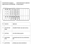
4
20
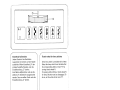
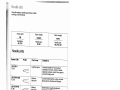
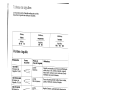
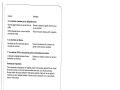
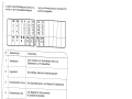
Tipptasten:
Die
verschiedenen
Modefle
haben
elne
unterschiedliche
Anzahi
von
Tipptasten
und
Programmen.
A,
B,
C
Knopflochtasten
Die
Taste
B
ist
gleichzeitig
die
Ausschalt
taste
zum
Lösen
der
getippten
Tasten
und
linke
Stichiage
(siehe
Seite
26).
D
Stretch-3fach-Zickzackstich
2
mm
Zickzackstich
2
mm
E
Stretch-3fach-Zickzackstich
3,5
mm
Zickzackstich
3,5
mm
F
Stretch-3fach-Zickzackstich
5
mm
Zickzackstich
5
mm
G
Stretch-3fach-Geradstich
G
eradstich
H
Pulloverstich
B
Ii
ndstich
I
Geschlossener
Overlockstich
Verbi
nd
u
ngsstich
K
Overlockstich
Muschelkantenstich
L
Federstich
Zierelastikstich
M
Wabenstich
Elastikstich
Bei
Modefl
1119
mu1,
zum
Nähen
der
Stiche
auf
den
Tipptasten
das
Zierstich
Einstellrad
ausgeschaltet
werden.
Dazu
den
wei1.en
Punkt
unter
die
Einstellmar
kierung
drehen,
siehe
Seite
27.
Im
Klappdeckel
ist
die
Programmtabelle
mit
den
Stichen
und
Stichkombinationen
abgebildet.
In
der
Tabelle
auf
den
Seiten
68-71
finden
Sie
die
dazugehorenden
Hinweise
für
ihre
Verwendung.
D’e
Buchstaben
der
Tasten
ihrer
Maschine
bestimmen
die
Programme
und
Kombina
tionen,
weiche
genäht
werden
können.
7
L___
-—J
________
III
__
H
K
L
M
A
B
C
D
E
F
Seite wird geladen ...
Seite wird geladen ...

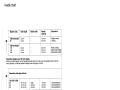
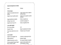
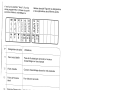
Nutzstiche
einstellen:
(weiRe
Symbole)
Taste
tippen
und
die
gewunschte
Stich
lange
zwischen
1
und
6
einstellen.
4
Alle
Zickzack-
und
Nutzstiche
werden
durch
zusätzliches
Tippen
der
Taste
G
in
der
Breite
halbiert.
Selecting
utility
stitches
(white
symbols)
Push
the
button
required
and
set
the
stitch
length
between
1
and
6.
All
zigzag,
and
utility
stitches
are
halved
in
width
when
button
G
is
pressed.
Réglage
des
points
utilitaires:
(symboles
blancs)
Appuyer
sur
Ia
touche
et
régler
Ia
Ion
gueur
de
point
désirée
entre
1
et
6.
En
appuyant
egalement
sur
Ia
touche
G,
tous
les
points
zigzag
et
utilitaires
sont
réduits
de
moitié
en
largeur.
I
punti
utili:
(simboli
bianchi)
Premere
il
tasto
e
regolare
Ia
lunghezza
del
punto
desiderata
tra
1-6.
Tutti
i
punti
a
zig-zag,
elastici
e
stretch
vengono
dimezzati
nella
loro
larghezza,
se
si
preme
in
aggiunta
il
tasto
G.
I

4
Stretchstiche
einstellen:
(rote
Symbole)
Taste
tippen
und
Stichlangen-Einsteller
bis
zum
Anschlag
auf
rotes
Symbol
stel
len.
Alle
Stretchstiche
werden
durch
zusätz
liches
Tippen
der
Taste
G
in
der
Breite
halbiert.
Selecting
stretch
stitches
(red
symbols>
Push
the
button
required
and
turn
the
stitch
length
control
as
far
as
it
will
go
(red
symbol).
By
also
pressing
button
G,
all
stretch
stit
ches
can
be
halved
in
width.
J
)
4
Regolazione
dei
punti
flexi
(stretch):
(simboli
rossi)
Premere
II
tasto
e
girare
il
regolatore
per
Ia
lunghezza
del
punto
fino
all’arresto
sul
simbolo
rosso.
4
Réglage
des
points
élastiques:
(symboles
rouges)
Appuyer
sur
Ia
touche
et
régler
le
règle
point
de
Ia
longueur
de
points
sur
le
sym
bole
rouge,
jusqu’à
Ia
butée.
Tous
les
points
élastiques
sont
réduits
de
moitié
en
appuyant
sur
Ia
touche
G.
U
Tutti
i
punti
flexi
51
dimezzano
in
lar
ghezza,
premendo
in
aggiunta
il
tasto
G.
-I
24
Seite wird geladen ...

4
C
1
D
__
Stichiage
einstellen
bei
Geradstich:
Selecting
the
needle
position
for
Stichiage
links:
Taste
B
tippen
straight
stitching
Stichiage
Mitte:
Taste
G
tippen
Left
needle
position:
push
button
B
Central
needle
position:
push
button
G
Deport
du
point
droit:
Regolazione
della
posizione
d’ago
nella
Deport
a
gauche:
appuyer
sur
Ia
touche
B
cucitura
diritta:
Deport
au
milieu:
appuyer
sur
Ia
touche
G
Posizione
ago
sinistra:
premere
tasto
B
Posizione
ago
centro:
premere
tasto
G
26

I
Siche
rheitsh
i
nweise
für
Haushaltnähmaschinen
nach
DIN
57
700
Teil
28
bzw.
IEC
335
Tell
28
a)
Der
Ben
utzer
hat
wegen
der
auf-
und
abgehenden
Nadel
genügend
Vorsicht
walten
zu
lassen
und
die
Nähstelle
bei
der
Arbeit
ständig
zu
beobachten.
b)
Beim
Verlassen
der
Maschine,
bei
Wartungsarbeiten
oder
beim
Wech
sein
von
mechanischen
Teilen
oder
Zubehör
ist
die
Maschine
durch
Her
ausziehen
des
Netzsteckers
aus
der
Steckdose
vom
Netz
zu
trennen.
c)
Die
maximal
zulässige
Leistung
der
Lampe
beträgt
15
Watt.
Some
safety
rules
a)
Take
care
to
avoid
injury
to
your
fin
gers
by
the
needle
during
sewing.
b)
Be
sure
to
unplug
the
power
cord
whenever
you
leave
the
machine
or
wish
to
clean
it,
oil
it
or
change
mechanical
and
accessory
parts.
c
Be
sure
to
use
only
a
15-watt
light
bulb
in
the
sewing
lamp.
Mesures
de
sécurité
a)
Toujours
faire
preuve
de
prudence
et
continuellement
surveiller
le
travail.
b)
Toujours
débrancher
Ia
machine
du
secteur
avant
de
quitter
Ia
machine,
avant
les
travaux
d’entretien
et
en
cas
de
remplacement
de
pièces
mécani
ques
ou
d’accessoires.
c)
Puissance
maximale
admissible
de
I’ampoule:
15
Watts.
Norme
di
sicurezza
per
macchine
per
cucire
per
uso
famiglia
secondo
DIN
57
700
parte
28
oppure
IEC
335
parte
28
a)
In
virtü
del
movimento
alternativo
dell’ago,
l’utente
deve
prestare
suffi
ciente
attenzione
e
tenere
costante
mente
d’occhio
il
punto
di
lavoro.
b)
Nel
cambiare
ago,
piedino,
spolina
e
placca
d’ago,
nelle
interruzioni
non
custodite
del
lavoro
e
durante
i
lavori
di
manutenzione
si
deve
disinserire
Ia
corrente
della
macchina
togliendo
Ia
spina
dalla
presa
a
muro.
c)
La
potenza
massima
consentita
per
Ia
lampadina
è
di
15
Watt.
Some
safety
rules
valid
for
United
Kingdom
only
The
wires
in
this
mains
lead
are
coloured
according
to
following
code:
Blue:
Neutral
Brown:
Live
As
the
colours
of
the
wires
in
the
mains
lead
of
this
appliance
may
not
correspond
with
the
colour
coding
of
the
terminals
in
your
plug,
proceed
as
follows:
the
wire
which
is
coloured
blue
must
be
connected
to
the
terminal
which
is
marked
with
the
letter
N
or
coloured
black.
The
wire
which
is
coloured
brown
must
be
connected
to
the
terminal
which
is
marked
with
the
letter
L
or
coloured
red.
Please
note:
When
a
13-ampere
plug
is
used
a
3-ampere
fuse
has
to
be
fitted.

oil
28
4
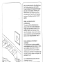
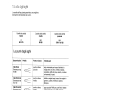
Thumb
wheel
for
fancy
stitches
Every
fancy
stitch
is
provided
with
a
letter.
Select
the
fancy
stitch
from
the
table.
Set
the
corresponding
letter
at
mark
“0”
by
turning
thumb
wheel
N.
For
sewing
utility
stitches,
thumb
wheel
N
for
fancy
stitches
must
be
disengaged.
To
do
so,
set
the
white
dot
at
mark
“0”.
Regolatore
punti
ornamentali
Ad
ogni
punto
ornamentale
corrisponde
una
lettera.
Scegliere
ii
punto
secondo
Ia
riproduzione
nella
tabella.
Col
selettore
di
registrazione
“N”
ruotare
Ia
lettera
deside
rata
sotto
Ia
marca
di
registrazione
“0”.
Per
cucire
con
i
punti
comuni
disinserire
ii
regolatore
“N”
del
punti
ornamentali.
Allo
scopo
ruotare
ii
punto
bianco
sotto
Ia
marca
di
registrazione
“0”.
[jirrflrjwij
N
—
-:
-
=
\
4
Einstellrad
für
Zierstiche
Jedem
Zierstich
ist
em
Buchstabe
zugeordnet.
Den
Zierstich
auf
der
Tabelle
auswählen.
Mit
dem
Einstellrad
,,N”
den
entsprechenden
Buchstaben
unter
die
Einstellmarkierung
,,O”
drehen.
Zum
Nähen
der
Nutzstiche
muR
das
Em
stellrad
,,
N”
der
Zierstiche
ausgeschaltet
werden.
Dazu
den
wei1en
Punkt
unter
die
Einstellmarkierung
,,O”
drehen.
Disque
de
réglage
des
points
d’orne
mentation
Chaque
point
d’ornementation
est
désigné
par
une
Iettre-code.
A
I’aide
du
disque
,,N”
placer
Ia
lettre-code
du
motif
désiré
sous
le
repère
,,0”.
Pour
pouvoir
coudre
les
points
utilitaires,
débrayer
le
disque
de
reglage
,,N”
des
points
d’ornementation
en
plaçant
le
point
blanc
de
ce
disque
sous
le
repère
,,O”.
Seite wird geladen ...

4
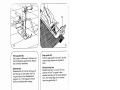
Unter
die
Nähfläche
greifen
und
diese
nach
links
schwenken.
Reach
under
the
work
support
and
swing
it
out
toward
the
left.
Passer
Ia
main
sous
Ia
bolte
de
rangement
et
faire
pivoter
celle-ci
vers
Ia
gauche.
Prendere
ii
piano
variabile
da
sotto
e
spostarlo
verso
sinistra.
4
Q
30

.1
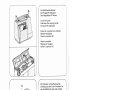
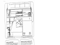
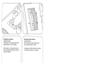
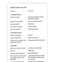
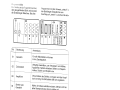
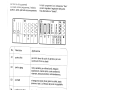
Verwandlungsnähfläche
und
Zubehör:
Nähfläche
kann
herausgenommen
werden
N.
Nähfläche
öffnen,
Zubehörkästchen
P
herausnehmen.
Unter
dem
Zubehärkäst
chen
ist
em
Zubehörfach
0.
Abbildung
Q
zeigt,
wie
Nähfü1e,
Nadein
und
Spulen
eingeordnet
werden
müssen.
o
Stopffu1
1
Normalnähfui
2
Kiarsichtfu1
3
Säumer
4
Biindstichfu1
5
Rei1verschlufMu1
6
Knopflochfu(
7
Lineal
4
Detachable
work
support
and
accessories:
)
The
work
support
can
be
lifted
out
(N).
Open
its
lid
and
take
out
accessory
box
R
Underneath
the
box
is
an
accessory
com
partment
0.
Illustration
Q
shows
hw
to
arrange
sewing
feet,
needles
and
bobbins
in
the
accessory
box.
o
Darning
foot
1
Standard
sewing
foot
2
Clear-view
foot
3
Hemmer
foot
4
Blindstitch
foot
5
Zipper
foot
6
Buttonhole
foot
7
Edge
guide
4
BoIte
de
rangement
et
accessoires:
Enlever
Ia
bolte
de
rangement
N,
l’ouvrir
et
enlever
Ia
boIte
d’accessoires
R
Sous
ceile-ci
se
trouve
le
casier
0.
Figure
0
vous
montre
comment
ranger
les
pieds
presseurs,
les
aiguilles
et
les
canettes.
O
Pied
a
repriser
1
Semelie
normale
2
Semelle
transparente
3
Pied
ourleur
4
Semelle
a
point
invisible
5
Semelle
pour
poser
Ia
fermeture
a
glissière
6
Semelle
pour
boutonniere
7
Guide-bord
4
II
piano
di
lavoro
variabile
e
gil
accessori:
II
piano
di
lavoro
puô
essere
tolto
(N).
Aprire
il
piano
di
lavoro,
togliere
ii
casset
tino
degli
accessori
R
Sotto
il
cassettino
degli
accessori
si
trova
uno
scomparto
per
accessori
0.
Figura
0
mostra
come
siste
mare
piedini,
aghi
e
spoline.
o
piedino
da
rammendo
1
piedino
normale
2
piedino
trasparente
3
orlatore
4
piedino
per
punto
invisibile
5
piedino
per
cerniere
6
piedino
per
occhielli
7
lineale
di
guida
Seite wird geladen ...

0
3
98-694
401-00
5
98-694
404-00
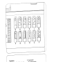
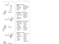
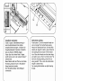
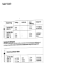
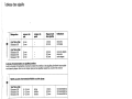
NähfüIe
(Normalzubehör)
0
Stopffu
1
NormalnähfuR
2
KlarsichtfuI
3
Säumer
Sewing
feet
(standard
accessories)
0
Darning
foot
4
Blindstitch
foot
1
Standard
sewing
5
Zipper
foot
6
Buttonhole
foot
7
Edge
guide
foot
2
Clear-view
foot
3
Hemmer
foot
Pieds
presseurs
(accessoires
standards)
0
Pied
a
repriser
5
Semelle
pour
1
Seme!le
normale
poser
Ia
2
Semelle
fermeture
a
transparente
glissière
3
Pied
ourleur
6
Semelle
pour
4
Semelle
a
point
boutonniere
invisible
7
Guide-bord
I
piedini
(corredo
normale)
0
piedino
da
4
piedino
per
punto
rammendo
invisibile
1
piedino
normale
5
piedino
per
2
piedino
cerniere
trasparente
6
piedino
per
3
orlatore
occhielli
7
lineale
di
guida
93-035
960-9
1
98-694
563-0
1
4
8lindstichfuI
5
Rei1,verschlugfug
6
Knopflochfu
7
Lineal
2
98-694
414-00
4
98-694
407-00
98-694
7
98-802
422-00
)

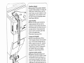
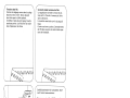
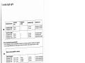
Blindstitching
toot
Blindstitching
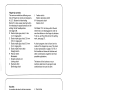
(Q):
turn
screw
R
to
set
guide
at
the
left.
The
guide
is
then
adjusted
according
to
the
needle
penetra—
tions.
The
folded
edge
of
the
material
runs
along
guide
edge
S.
I
4
Lineale
di
guida
(N):
Infilare
II
lineale
nel
foro
0
e
avvitare
Ia
vite
P
dopo
aver
regolato
Ia
distanza
desi
derata.
Piedino
per
punto
invisibile:
Punto
invisibile
(Q):
Portare
con
vite
R
Ia
guida
verso
sinistra.
La
guida
viene
quindi
regolata
per
Ia
corretta
entrata
dell’ago.
La
piegatura
della
stoffa
scorre
lungo
ii
bordo
di
guida
S.
4
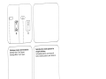
4
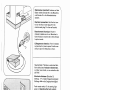
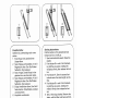
FUhrungslineal
(N):
Das
Lineal
in
die
Bohrung
0
schieben
und
nach
Einstellen
des
gewünschten
Abstan
des
Schraube
P
festdrehen.
Blindstichfu(:
Blindstichnähen
(Q):
Mit
der
Schraube
R
die
Fuhrung
nach
links
stellen.
Die
Füh
rung
wird
dann
für
den
Nadeleinstich
reguliert.
An
der
Fuhrungskante
S
läuft
der
Bruch
des
Oberstoffes
entlang.
Edge
guide
(N):
Push
the
edge
guide
into
hole
0,
set
the
required
edge
distance
and
tighten
it
there.
Guide-bord
(N):
Glisser
le
guide-bord
dans
le
trou
0,
régler
Ia
distance
souhaitée
et
resserrer
ensuite
Ia
vis
P.
Pied
a
point
invisible:
Couture
au
point
invisible
(Q):
Déplacer
le
guide
a
gauche
par
Ia
vis
R.
Le
guide
est
régle
pour
Ia
pénétration
de
l’aiguille
dans
le
tissu.
La
cassure
du
tissu
supérieur
longe
Ie
bord
du
guide
S.
}
34

4
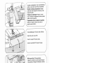
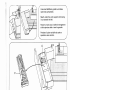
Stopffuf:
Die
Nadel
hochstellen.
Den
Bugel
P
nach
hinten
drUcken
und
festhalten.
Den
Stift
des
Fuf.es
in
die
Bohrung
N
einführen,
die
Gabel
R
greift
dabei
urn
die
Stoffdrücker
stange,
und
den
Fu1
bis
zurn
Anschlag
einsetzen.
Den
Bugel
P
loslassen,
wobei
er
sich
auf
die
Halteschraube
Q
legt.
Die
Schraube
0
festdrehen.
Beim
Stopfen
mit
Wolle
wird
der
Wolifa
den
in
die
Fuhrung
S
gezogen.
Darning
foot:
Position
the
needle
up.
Push
bar
P
to
the
back
and
hold
it
there.
Fit
the
pin
of
the
foot
in
hole
N;
at
the
same
time,
fork
R
engages
the
presser
bar,
and
push
the
foot
fully
in.
Let
go
of
bar
P,
which
then
rests
on
retaining
screw
Q.
Tighten
screw
0.
For
wool
darning
the
woollen
thread
is
pulled
into
guide
S.
j
Pied
a
repriser:
Lever
Ia
barre
a
aiguille.
Déplacer
l’étrier
P
vers
l’arrière
et
le
maintenir.
Introduire
le
tenon
de
Ia
semelle
dans
le
trou
N;
Ia
fourche
R
entoure
Ia
barre
du
pied
pres
seur;
introduire
le
pied
jusqu’à
Ia
butée.
Lâcher
l’étrier
P;
il
se
pose
sur
Ia
vis
de
maintien
Q.
Ensuite
resserrer
Ia
vis
0.
En
reprisant
de
Ia
lame,
enfiler
le
fil
de
lame
dans
le
guide
S.
4
II
piedino
da
rammendo:
Aizare
l’ago.
Premere
Ia
staffa
P
verso
dietro
e
tenerla
ferma.
Inserire
il
perno
del
piedino
nel
foro
N,
Ia
forcella
R
si
aggan
cia
in
tal
maniera
sulla
barra
premistoffa,
quindi
innestare
il
piedino
fino
all’arresto.
Rilasciare
Ia
staffa
P
che
si
appoggerà
sulla
vite
di
fissaggio
Q.
Avvitare
Ia
vite
0.
Rammendando
con
lana
infilarla
nella
guida
S.
\
35

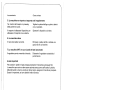
ReiBverschluIfuI:
Den
hinteren
Steg
in
die
Nute
N
einhän
gen,
den
Fuf
vorne
hochdrücken
und
in
die
Nute
0
einrasten.
Je
nach
Verarbeitung
kann
der
ReiLver
schlu1fuI
nach
links,
Abbildung
P
oder
rechts,
Abbildung
Q
verschoben
werden.
Zipper
foot:
Push
the
rear
stud
into
slot
N.
Then
push
the
foot
up
until
it
snaps
in
place
in
slot
0.
The
zipper
foot
can
be
moved
to
the
left
(Fig.
P)
or
right
(Fig.
Q),
as
required.
Pied
pour
fermeture
a
glissiére:
Accrocher
Ia
tige
arrière
dans
Ia
rainure
N
et
soulever
Ia
semelle
du
pied
a
l’avant
pour
l’engager
dans
Ia
rainure
0.
Suivant
besoin,
le
pied
pour
fermeture
a
glissière
peut
être
déplacé
vers
Ia
gauche
(fig.
P)
ou
vers
Ia
droite
(fig.
Q).
Piedino
per
cerniere
lampo:
Agganciare
il
perno
posteriore
nella
scanalatura
N,
premere
ii
piedino
davanti
in
su
e
agganciarlo
nella
scanalatura
0.
A
secondo
della
lavorazione
Si
puô
spostare
il
piedino
per
ceniera
a
sinistra
P
o
a
destra
Q.
36
Seite wird geladen ...
Seite wird geladen ...
Seite wird geladen ...
Seite wird geladen ...
Seite wird geladen ...
Seite wird geladen ...
Seite wird geladen ...
Seite wird geladen ...
Seite wird geladen ...
Seite wird geladen ...
Seite wird geladen ...
Seite wird geladen ...
Seite wird geladen ...
Seite wird geladen ...
Seite wird geladen ...
Seite wird geladen ...
Seite wird geladen ...
Seite wird geladen ...
Seite wird geladen ...
Seite wird geladen ...
Seite wird geladen ...
Seite wird geladen ...
Seite wird geladen ...
Seite wird geladen ...
Seite wird geladen ...
Seite wird geladen ...
Seite wird geladen ...
Seite wird geladen ...
Seite wird geladen ...
Seite wird geladen ...
Seite wird geladen ...
Seite wird geladen ...
Seite wird geladen ...
Seite wird geladen ...
Seite wird geladen ...
Seite wird geladen ...
Seite wird geladen ...
Seite wird geladen ...
Seite wird geladen ...
-
 1
1
-
 2
2
-
 3
3
-
 4
4
-
 5
5
-
 6
6
-
 7
7
-
 8
8
-
 9
9
-
 10
10
-
 11
11
-
 12
12
-
 13
13
-
 14
14
-
 15
15
-
 16
16
-
 17
17
-
 18
18
-
 19
19
-
 20
20
-
 21
21
-
 22
22
-
 23
23
-
 24
24
-
 25
25
-
 26
26
-
 27
27
-
 28
28
-
 29
29
-
 30
30
-
 31
31
-
 32
32
-
 33
33
-
 34
34
-
 35
35
-
 36
36
-
 37
37
-
 38
38
-
 39
39
-
 40
40
-
 41
41
-
 42
42
-
 43
43
-
 44
44
-
 45
45
-
 46
46
-
 47
47
-
 48
48
-
 49
49
-
 50
50
-
 51
51
-
 52
52
-
 53
53
-
 54
54
-
 55
55
-
 56
56
-
 57
57
-
 58
58
-
 59
59
-
 60
60
-
 61
61
-
 62
62
-
 63
63
-
 64
64
-
 65
65
-
 66
66
-
 67
67
-
 68
68
-
 69
69
-
 70
70
-
 71
71
-
 72
72
-
 73
73
-
 74
74
-
 75
75
-
 76
76
-
 77
77
-
 78
78


Pfaff Tipmatic 1119 Bedienungsanleitung
- Kategorie
- Nähmaschinen
- Typ
- Bedienungsanleitung
- Dieses Handbuch eignet sich auch für
in anderen Sprachen
- English: Pfaff Tipmatic 1119 Owner's manual
- français: Pfaff Tipmatic 1119 Le manuel du propriétaire
- italiano: Pfaff Tipmatic 1119 Manuale del proprietario
Verwandte Artikel
-
Pfaff tipmatic 1045 Bedienungsanleitung
-
-
-
-
-
-
-
-
-