ATEN CE250a Schnellstartanleitung
- Kategorie
- KVM-Schalter
- Typ
- Schnellstartanleitung

Quick Start Guide
KVM Extender
© Copyright 2012 ATEN
®
International Co., Ltd.
ATEN and the ATEN logo are trademarks of ATEN International Co., Ltd. All rights reserved. All other
trademarks are the property of their respective owners.
This product is ROHS compliant.
Part No. PAPE-1223-204G Printing Date: 09/2012
CE250
A
KVM Extender Quick Start Guide
Guide de mise en route du système CE250
A
KVM Extender
CE250
A
KVM-Verlängerung Kurzanleitung
Sistema de extensión KVM CE250
A
Guía rápida
CE250
AL
(Local Unit)
CE250
A
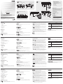
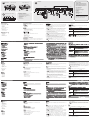
Front View
A
CE250
AL
(Local Unit)
1. Grounding Terminal
2. KVM Port
3. Remote LED
4. Local LED
5. Operating Mode Selection Switch
CE250
AR
(Remote Unit)
1. Grounding Terminal
2. On line LED
3. Power LED
Rear View
B
CE250
AL
/CE250
AR
1. Power Jack
2. Mouse Port
3. Keyboard Port
4. Link Port
5. Video Port
System Requirements:
Console
• AVGA,SVGA,orMultisyncmonitorcapableofthehighestresolutionthatyouwillbeusing
on any computer in the installation
• APS/2stylekeyboard
• APS/2stylemouse
Computers
The following equipment must be installed on each computer that is to be connected to the
system:
• AVGA,SVGA,orMultisynccard
• A6-pinmini-DINmouseport
• A6-pinmini-DINKeyboardport
Operating Systems
• Windows2000andhigher
• Redhat7.1andhigher;Mandrake/Mandriva9.0andhigher
• SuSE9.0andhigher
• AIX4.3,5L(5.2,5.3)andhigher
• FreeBSD4.2,4.5andhigher
• Netware6.0andhigher
• OS/2Warpandhigher
Hardware Installation
Grounding
To prevent damage to your installation it is important that all devices are properly grounded.
Refer to the user manual for grounding procedures.
Connecting Up
C
Refer to the installation diagram (the numbers in the diagram correspond to the numbers of
the steps) as you perform these steps:
1. Plug the cables from the local console devices, into their ports on the rear panel of the
Local Unit (CE250
AL
).
2. Plug the SPHD end of the KVM cable supplied with this unit into the KVM port on the front
panel of the CE250
AL
.
Note:
The shape and function of the connectors on the cable and KVM switch have been
modiedsothatonlyKVMcablesdesignedtoworkwiththisswitchcanbeused.
3. Plug the connectors on the other end of the cable into the appropriate ports on the
computer (or Console section of the KVM switch - if you are using one). Each connector is
marked with an appropriate icon to indicate itself.
4. Plug one end of a Cat 5 cable into the CE250
AL
's Remote I/O port. Plug the other end of
the cable into the CE250
AR
’s Remote I/O port.
Note:
Cat 5 cable is not supplied with this package. It requires a separate purchase. The
cable length can be up to 150 m (500').
5. Plug the cables from the remote console devices (keyboard, monitor, and mouse), into
their ports on the Console side of the CE250
AR
.
6.Plugthepoweradapter(suppliedwiththispackage)intoanACsource;plugtheadapter's
power cable into the CE250
AR
's (Remote Unit) Power Jack.
7.IfyouchoosetouseapoweradapterwiththeCE250
AL
, plug the power adapter into an AC
source;plugtheadapter'spowercableintotheCE250
AL
's Power Jack.
Note:
Use of a power adapter with the CE250
AL
is optional. The Local unit (CE250
AL
) can
get its power from the computer – external power is only required when the power
fromthelocalcomputer/computersintheKVMinstallationisinsufcient.
Operation
Operating Modes
The CE250
A
KVM Extender has two operating modes:Local, and Remote, as described in the
table below:
Mode Selection
The Operating Mode Selection Switch, located on the CE250
AL
’s front panel, controls the
operating mode of the CE250
A
KVM Extender system. Pressing the switch toggles the
CE250
A
between Local and Remote operating modes.
Mode Description
Local
Only the local console has access. The remote console’s monitor
is blank, and the remote console’s keyboard and mouse input is
disabled.
Local / Remote
BoththelocalandremoteconsolescanhaveKVMaccess.
However, they cannot both have access at the same time. The
console without access has to wait until the console with access
stops inputting data before it can gain access.
CE250
AR
(Remote Unit)
Vue avant
A
CE250
AL
(unité locale)
1. Bornedeterre
2. Port KVM
3. Voyant de connexion distante (Remote)
4. Voyant de connexion locale (Local)
5. Boutondesélectiondumodedefonctionnement
CE250
AR
(unité distante)
1. Bornedeterre
2. Voyant de connexion en ligne (On Line)
3. Voyant d'alimentation (Power)
Vue arrière
B
CE250
AL
/CE250
AR
1. Prise d'alimentation
2. Port souris
3. Port clavier
4. Port de liaison
5. Port vidéo
Conguration système
Console
• UnmoniteurVGA,SVGAouMultisyncprenantenchargelaplushauterésolutionàutiliser
surlesordinateursàinstaller
•UnclavierPS/2
•UnesourisPS/2
Ordinateurs
Lescomposantssuivantsdoiventêtreinstalléssurchaqueordinateuràconnecterausystème:
•UnecarteVGA,SVGAouMultisync
•Unportsourismini-DINà6broches
•Unportclaviermini-DINà6broches
Systèmes d'exploitation
• Windows2000ousupérieur
• Redhat7.1ousupérieur;Mandrake/Mandriva9.0ousupérieur
• SuSE9.0ousupérieur
• AIX4.3,5L(5.2,5.3)
• FreeBSD4.2,4.5
• Netware6.0ousupérieur
• OS/2Warpousupérieur
Installation du matériel
Borne
And'éviterd'endommagervotreinstallation,vériezquetouslespériphériquessont
correctementreliésàlaterre.Pourplusd'informationssurlesprocéduresdemiseàlaterre,
consultez le manuel d'utilisation.
Installation
C
Reportez-vous au schéma de connexion (les numéros du schéma correspondent aux
numéros des étapes ci-dessous) en procédant comme suit :
1.Branchezlescâblesdespériphériquesdeconsolelocauxsurlesportsrespectifssituésà
l'arrière de l'unité locale CE250
AL
.
2.Branchezl'extrémitéSPHDducâbleKVMfourniaveccetteunitésurleportKVMsituéà
l'avant de l'unité locale CE250
AL
.
Remarque :
laformeetlafonctiondesconnecteursducâbleetducommutateurKVM
ontétémodiéesdefaçonàcequeseulslescâblesKVMconçuspour
fonctionner avec ce commutateur puissent être utilisés.
3.Branchezlesconnecteursdel'autreextrémitéducâblesurlesportsrespectifsde
l'ordinateur (ou de la partie console du commutateur KVM, si vous en utilisez un). Chaque
connecteurestassociéàuneicônespéciquepermettantdeledistinguerfacilement.
4.Branchezuneextrémitéducâbledecatégorie5surleportRemoteI/O(E/Sdistantes)
de l'unité locale CE250
AL
.Branchezl'autreextrémitéducâblesurleportRemoteI/Ode
l'unité distante CE250
AR
.
Remarque :
lecâbledecatégorie5n'estpasfourniavecceproduit.Ildoitêtreacheté
séparément et ne doit pas mesurer plus de 150 m.
5.Branchezlescâblesdespériphériquesdeconsoledistants(clavier,moniteuretsouris)sur
les ports respectifs de la partie console de l'unité distante CE250
AR
.
6.Connectezuneextrémitéducâbledel'adaptateursecteurfourniàuneprisedecourant,et
l'autreextrémitéàlaprised'alimentationdel'unitédistanteCE250
AR
(unité distante).
7.Sivoussouhaitezutiliserunadaptateursecteuravecl'unitélocaleCE250
AL
, connectez
uneextrémitéducâbledel'adaptateuràuneprisedecourant,etl'autreextrémitéàla
prise d'alimentation de l'unité locale CE250
AL
.
Remarque :
l'utilisation d'un adaptateur secteur avec l'unité locale CE250
AL
est
facultative. L'unité locale (CE250
AL
) peut être alimentée par l'ordinateur. Une
alimentation externe est uniquement nécessaire si l'alimentation fournie par
leoulesordinateurslocauxdel'installationKVMestinsufsante.
Utilisation
Modes de fonctionnement
MisàpartlemodelesystèmeCE250
A
KVM Extender offre deux modes de fonctionnement :
Local (connexion locale) et Remote (connexion distante), décrits dans le tableau ci-dessous :
Sélection du mode
Leboutondesélectiondumodedefonctionnement,situéàl'avantdel'unitélocaleCE250
AL
,
contrôlelemodedefonctionnementdusystèmeCE250
A
KVM Extender. Appuyez sur ce
bouton pour basculer entre les modes de fonctionnement Local et Remote du système
CE250
A
.
Mode Description
Local
Seulelaconsolelocaleyaaccès.Riennes'afchesurl'écrande
la console distante, et l'entrée de son clavier et de sa souris est
désactivée.
Local /Remote
La console locale comme la console distante peuvent avoir le
contrôleKVM.Ellesnepeuventtoutefoispasl'avoirenmêmetemps.
Avantd'yavoiraccès,laconsolen'ayantpaslecontrôledoitpatienter
jusqu'àcequecelleayantlecontrôlecessed'entrerdesdonnées.
Vorderseitige Ansicht
A
CE250
AL
(lokales Gerät)
1. Erdungsanschluss
2. KVM-Port
3. Remote-LED
4. Local-LED
5. Betriebsmodus-Auswahlschalter
CE250
AR
(Gerät für Gegenstelle)
1. Erdungsanschluss
2. Online-LED
3. LED-Betriebsanzeige
Rückseitige Ansicht
B
CE250
AL
/CE250
AR
1. Stromeingangsbuchse
2. Mausanschluss
3. Tastaturanschluss
4. Verbindungs-Port
5. Grakeingang
Systemvoraussetzungen
Konsole
• EinVGA-,SVGA-oderMultisync-Monitor,derinderLageist,diehöchsteAuösung
darzustellen,dieSieaufeinemderzuinstallierendenComputerverwendenmöchten
• EinePS/2-Tastatur
• EinePS/2-Maus
Computer
Auf den Computern, die mit dem System verbunden werden sollen, muss mindestens
Folgendesinstalliertsein:
• EineVGA-,SVGA-oderMultisync-Grakkarte
• Ein6-poligerMini-DIN-Mausport
• Ein6-poligerMini-DIN-Tastaturport
Betriebssysteme
• Windows2000oderhöher
• Redhat7.1oderhöher;Mandrake/Mandriva9.0oderhöher
• SuSE9.0oderhöher
• AIX4.3,5L(5.2,5.3)
• FreeBSD4.2,4.5
• Netware6.0oderhöher
• OS/2Warpoderhöher
Hardware installieren
UmeineBeschädigungIhrerGerätezuvermeiden,müssenalleGeräteordnungsgemäß
geerdetsein.FürweitereDetailszurErdung,siehedasBenutzerhandbuch.
installieren
C
Siehe das Installationsdiagramm (die Zahlen im Diagramm entsprechen der Reihenfolge),
undgehenSiefolgendermaßenvor:
1.VerbindenSiedieKabelderlokalenKonsolgerätemitdenentsprechendenBuchsenauf
der Rückseite des lokalen Gerätes (CE250
AL
).
2. Verbinden Sie den SPHD-Stecker des mitgelieferten KVM-Kabels mit dem KVM-Port auf
der Vorderseite des CE250
AL
.
Hinweis:
Formund Belegungder Stiftedieses Steckersund KVM-Switches wurdenso
hergestellt,dassnurKVM-Kabelangeschlossenwerdenkönnen,diefürdiesen
Switch geeignet sind.
3. Verbinden Sie die Stecker am anderen Kabelende mit den betreffenden Anschlüssen
am Computer (oder des Konsolabschnitts des KVM-Switches, wenn Sie einen
solchenverwendenmöchten).JederAnschlussistdurcheinentsprechendesSymbol
gekennzeichnet.
4. Verbinden Sie ein Ende des Kat. 5-Kabels mit dem Anschluss Remote I/O des CE250
AL
.
Verbinden Sie das andere Ende des Kabels mit dem Anschluss Remote I/O des CE250
AR
.
Hinweis:
Das Kat. 5-Kabel ist nicht im Lieferumfang enthalten. Sie müssen es separat
erwerben. Die Kabellänge darf maximal 150 m betragen.
5. Verbinden Sie die Kabel der Konsolgeräte der Gegenstelle (Maus, Tastatur, Monitor) mit
denentsprechendenBuchsenimKonsolabschnittdesCE250
AR
.
6.Verbinden Sie das mitgelieferte Netzteil mit einer Steckdose und sein Netzkabel mit der
Stromeingangsbuchse des CE250
AR
(Gerät für Gegenstelle).
7.WennSieeinNetzteilfürdenCE250
AL
verwendenmöchten,verbindenSiediesesmit
einer stromführenden Steckdose, und verbinden Sie das Kabel des Netzteils mit der
Stromeingangsbuchse des CE250
AL
.
Hinweis:
Die Speisung des CE250
AL
über ein Netzteil ist optional. Das lokale Gerät
(CE250
AL
) kann direkt über den Computer gespeist werden – eine externe
Stromversorgung ist nur erforderlich, wenn der lokale Computer bzw. die
Computer aus der KVM-Installation nicht ausreichend Strom zur Verfügung
stellen.
Bedienung
Betriebsmodi
Die CE250
A
KVM-VerlängerungunterstütztzweiBetriebsarten:LokalundGegenstelle,siehe
folgende Tabelle:
Betriebsartauswählen
DieBetriebsart-AuswahltasteaufderVorderseitedesCE250
AL
steuertdieBetriebsartdes
gesamten CE250
A
KVM-Systems. Drücken Sie die Taste, um die Steuerung zwischen den
beiden CE250
A
-Einheiten umzuschalten (lokal und Gegenstelle).
Betriebsart Beschreibung
Lokal
Nur die lokale Konsole hat Zugriff. Der Monitor der Konsole der
Gegenstelle bleibt dunkel, und Tastatur und Maus der Gegenstelle
sind deaktiviert.
Lokal /
Gegenstelle
SowohldielokalealsauchdieKonsolederGegenstellekönnendie
KVM-Steuerungübernehmen.AllerdingskönnennichtbeideKonsolen
gleichzeitigeingesetztwerden.BevorsieZugrifferhält,mussdie
Konsole ohne Zugriff warten, bis die Konsole mit aktuellem Zugriff die
Dateneingabe stoppt.
Vista frontal
A
CE250
AL
(unidad local)
1. Terminal de tierra
2. Puerto KVM
3. Indicador de conexión remota (Remote)
4. Indicador de conexión local (Local)
5. Conmutador del modo operativo
CE250
AR
(unidad remota)
1. Terminal de tierra
2. Indicador de conexión en línea (On Line)
3. Indicador de alimentación (Power)
Vista posterior
B
CE250
AL
/CE250
AR
1. Entrada de alimentación
2. Puerto de ratón
3. Puerto de teclado
4. Puerto de enlace
5. Puertográco
Requisitos del sistema
Consola
• UnmonitorVGA,SVGAoMultisynccapazderepresentarlaresoluciónmáselevadaque
vaya a usar con cualquiera de los ordenadores a instalar
• UntecladoPS/2
• UnratónPS/2
Ordenadores
En cada ordenador que vaya a conectar al sistema se tienen que instalar los siguientes
componentes:
• UnatarjetagrácaVGA,SVGAoMultisync
• Unpuertomini-DINpararatónde6patillas
• Unpuertomini-DINparatecladode6patillas
Sistemas operativos
• Windows2000osuperior
• Redhat7.1osuperior;Mandrake/Mandriva9.0osuperior
• SuSE9.0osuperior
• AIX4.3,5L(5.2,5.3)
• FreeBSD4.2,4.5
• Netware6.0osuperior
• OS/2Warposuperior
Instalación del hardware
Conexión a tierra
Paraevitardañosenlosdispositivos,veriquequetodosellosesténconectadosatierra
correctamente. Consulte el manual de usuario para más información sobre la conexión a
tierra.
Instalación
C
Véase el diagrama de instalación (los números en el diagrama equivalen a los números de
los pasos a seguir) y proceda como se indica a continuación:
1. Conecte los cables de los dispositivos de la consola local a los puertos respectivos
situados en el panel posterior de la unidad local CE250
AL
.
2. Conecte el extremo SPHD del cable KVM que viene con esta unidad al puerto KVM
situado en el panel frontal de la unidad local CE250
AL
.
Nota:
la forma y la función de los conectores del cable y del conmutador KVM han sido
modicadasdemaneraquesólosepuedanutilizarloscablesKVMdiseñadospara
funcionar con este conmutador.
3. Enchufe los conectores del otro extremo del cable a los puertos respectivos del ordenador
(o a la sección de consola del concentrador KVM en caso de que desee utilizar una).
Cada conector viene marcado con un icono correspondiente.
4. Conecte un extremo del cable de Cat. 5 al puerto Remote I/O de la unidad local CE250
AL
.
Conecte el otro extremo del cable al puerto Remote I/O de la unidad remota CE250
AR
.
Nota:
el cable de Cat. 5 no está incluido en el paquete. Deberá adquirirlo por separado.
Su longitud máxima puede ser de 150 m.
5. Conecte los cables de los dispositivos de la consola remota (teclado, monitor y ratón) a
los puertos de consola respectivos de la unidad remota CE250
AR
.
6.Conecteunextremodelcabledeladaptadordealimentaciónincluidoaunatomaeléctrica
y el otro extremo a la entrada de alimentación de la unidad remota CE250
AR
(unidad
remota).
7.SideseautilizarunadaptadordealimentaciónconlaunidadlocalCE250
AL
, conecte un
extremo del cable de adaptador a una toma eléctrica y el otro extremo a la entrada de
alimentación de la unidad local CE250
AL
.
Nota:
el uso de un adaptador de alimentación con la unidad local CE250
AL
es opcional.
Se puede alimentar la unidad local (CE250
AL
) mediante el ordenador. Una
alimentación externa sólo es necesaria si la alimentación suministrada por el o los
ordenadoreslocalesdelainstalaciónKVMesinsuciente.
Funcionamiento
Modos operativos
Aparte del modo el sistema de extensión KVM CE250
A
ofrece dos modos operativos: Local
(conexión local) y Remote (conexión remota), que se describen en la siguiente tabla:
Selección de modo
El conmutador del modo operativo, situado en el panel frontal de la unidad local CE250
AL
,
controla el modo operativo del sistema de extensión KVM CE250
A
. Pulse este botón para
alternar entre los modos operativos Local y Remota del sistema CE250
A
.
Modo Descripción
Local
Sólo la consola local tiene acceso. No aparece nada en el monitor de
la consola remota, y su teclado y ratón están desactivados.
Local /Remote
Tanto la consola local como la remota pueden tener el control KVM.
Sin embargo, no lo pueden tener al mismo tiempo. Antes de conseguir
el acceso, la consola que no tiene el control KVM debe esperar hasta
que la consola que lo tiene deje de entrar datos.
www.aten.com
www.aten.com
www.aten.com
www.aten.com
Important Notice
Considering environmental protection, ATEN does not
provide a fully printed user manual for this product. If
the information contained in the Quick Start Guide is not
enoughforyoutocongureandoperateyourproduct,
please visit our website www.aten.com, and download the
full user manual.
Online Registration
http://eservice.aten.com
Technical Phone Support
International:
886-2-86926959
North America:
1-888-999-ATEN Ext: 4988
United Kingdom:
44-8-4481-58923
Package Contents
1 CE250AL KVM Extender (Local Unit)
1 CE250AR KVM Extender (Remote Unit)
1 Custom KVM Cable (1.8 m)
1 Power Adapter
1 Mounting Kit
1 User Instructions
Rear View
(CE250
AL
/ CE250
AR
)
B
1 2 3 4 5
C
CE250
AR
CE250
AL
4
1
7
4
6
11
5
55
(Optional)
CE250
AL
2
3
Allinformation,documentation,andspecications
contained in this media are subject to change without
priornoticationbythemanufacturer.Pleasevisitour
websitetondthemostuptodateversion.
A
FrontView
2 3 4 51
2 31
Seite wird geladen ...
-
 1
1
-
 2
2


ATEN CE250a Schnellstartanleitung
- Kategorie
- KVM-Schalter
- Typ
- Schnellstartanleitung
in anderen Sprachen
- English: ATEN CE250a Quick start guide
- français: ATEN CE250a Guide de démarrage rapide
- español: ATEN CE250a Guía de inicio rápido
- italiano: ATEN CE250a Guida Rapida
Verwandte Artikel
-
ATEN CE250a Schnellstartanleitung
-
ATEN CE750 Schnellstartanleitung
-
ATEN CE770 Schnellstartanleitung
-
-
ATEN CE252 Schnellstartanleitung
-
ATEN CE800 Schnellstartanleitung
-
ATEN CE800b Schnellstartanleitung
-
ATEN CL5800 Schnellstartanleitung
-
ATEN CE370 Schnellstartanleitung
-
ATEN CE100 Benutzerhandbuch