
DTD01
Tank Discharge
Control
EN
DE
FR
ES
NL
IT
FI
SV
DA
NO
Tank Discharge Control
Instruction manual................... 5
Tankentsorgungssteuerung
Einbauanleitung.................... 13
Commande d'évacuation du réservoir
Mode d'emploi .....................19
Control de descarga del depósito
Manual de instrucciones..............26
Tank-afvoerregeling
Gebruiksaanwijzing..................33
Comando di scarico del serbatoio
Manuale di istruzioni .................39
Säiliön tyhjennysohjaus
Ohjekirja...........................45
Styrning för tanktömning
Bruksanvisning .....................51
Tankudledningsstyring
Instruktionsvejledning ................57
Styreanordning for tømming av tank
Brukerhåndbok .....................63

2
Dometic Tank Discharge Control
1
1
2
3
4
5
6
7
2
4
5
3
1
3
2
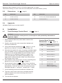
A
B
C
D

3
1
2
3
4
5
Dometic Tank Discharge Control

4
Dometic Tank Discharge Control
1
2
4
3
6
7

5
1 Notes on using the manual .................................................... 5
2 General safety instructions .................................................... 5
3 Intended use ............................................................ 5 - 6
4 Components ............................................................... 6
5 Specications ........................................................... 6 - 7
6 Installation .............................................................. 7 - 8
7 Operation............................................................... 8 - 9
8 Warranty and Product Liability ............................................. 9 - 10
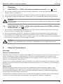
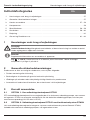
1 Notes on using the manual
Note
Supplementary information for operating the device.
fig. 2 1, page 2 : This refers to an element in an illustration. In this example, item 1 in
gure 2 on page 2.
2
Caution!
Safety Instruction: Failure to observe this instruction can cause material damage and
impair the function of the device.
EN
Table of contents
Dometic Tank Discharge Control Notes on using the manual
2 General safety instructions
The manufacturer will not be held liable for claims for damage resulting from the following:
• Faulty assembly or connection
• Damage to the unit from mechanical inuences, misuse or abuse
• Alterations to the unit without express written permission from the manufacturer
• Use for purposes other than those described in the operating manual
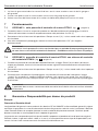
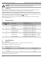
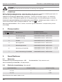
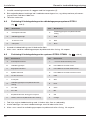
3 Intended use
3.1 OPTION 1: DTD01 discharge control panel only
DTD Tank Discharge Control panel provides a key-operated switch to activate a discharge pump that
will empty a holding tank. The DTD01 can be used with virtually any electric discharge pump that
operates on the same rated voltage (12 V DC or 24 V DC).
3.2 OPTION 2: DTD01 discharge control panel with DTM04 tank monitor system
When integrated with the Dometic DTM04 Tank Monitor System, the DTD Tank Discharge Control panel
will automatically shut off the discharge pump when the holding tank is empty.

6
Dometic Tank Discharge ControlIntended use
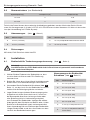
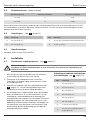
System Voltage Pump Off (amp) Pump On (amp)
12 V DC 0 0.16
24 V DC 0 0.095
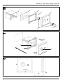
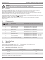
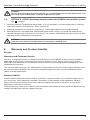
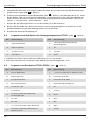
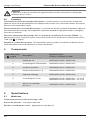
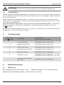
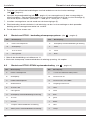
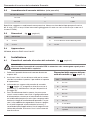
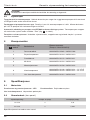
4 Components
Items in fig.
1 page 2
Description Item Number (Europe / North America)
1 Replacement key 860003853110362 / 385311036
2 Switch assembly 860003853116104 / 385311610
3 Panel cover 860003853116112 / 385311611
4 #6 fastener 860003853116120 / 385311612
5 Mounting frame 860003853116138 / 385311613
6 Circuit assembly
860003853116146 / 385311614 – 12 V DC
860003853116153 / 385311615 – 24 V DC
7 Circuit assembly housing 860003853116161 / 385311616
1
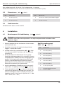
5 Specifications
5.1 Materials
3.3 Features
Secure discharge pump control. Key-operated switch provides convenient means to secure
discharge pump operation without use of padlocks or other mechanical fasteners.
Helps prevent pump burn-out. Activated panel light indicates when discharge pump is operating.
Reminds operator to shut off pump when tank discharge is complete.
Automatic pump shut-off with DTM04 tank monitor system. Discharge pump stops when tank level
drops below “Empty” level probe (g. 6 4, page 4).
Simplifies plumbing system. Eliminates wye valves, seacocks and vented loops of multiple
toilet systems.
5.2 Electrical Current Draw (panel only)
Panel frame and mounting frame: ABS Panel surface: Polycarbonate resin
Circuit assembly housing: High-density polyethylene
6
Specications subject to change without notice.
Caution!
Operator must know local regulations for emptying a holding tank.

7
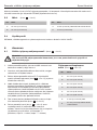
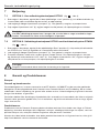
6 Installation
1. Select panel location away from direct contact with
water and oil.
2. Conrm clearance for wire connections behind wall,
hull liner or bulkhead.
3. Using control panel template (g. 8 , page 11), cut out
panel access hole (E, F) and drill fastener holes (G).
4. With electrical power off, route 14-gauge stranded copper
wire from power source, through discharge pump circuit
breaker or fuse (not provided), to panel location. Route
additional wire according to diagram on page 3 or 4
(see wiring diagram keys below), depending on your
application, to panel location. Make sure wires extend
out through access hole.
5. Make proper wiring connections to wires extending from
bottom of circuit assembly (g. 2 4, page 2).
6. Remove panel cover (g. 2 1, page 2) from mounting
frame (2) by carefully pulling them apart. Make sure wires
between key switch (3) and circuit assembly (4) remain
attached. (Key pin 1 – red; pin 2 – brown; pin 7 – blue.)
7. Install mounting frame to wall with four fasteners (5).
8. Tuck key switch wires into circuit assembly housing,
and push panel cover onto mounting frame until it
locks into place.
9. Turn on electrical power.
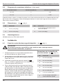
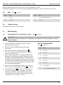
6.1 Tank Discharge Control Panel (g. 2 , page 2)
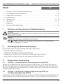
Control Panel Template
Dimensions (g. 8 , page 11)
2
Dometic Tank Discharge Control Specifications
Caution!
Do not install DTD control panel in an atmosphere with potentially flammable or
explosive vapors.
Ref. Dimension
A 83 mm (3.25 in.)
B 83 mm (3.25 in.)
C 67 mm (2.63 in.)
D 67 mm (2.63 in.)
E 55 mm (2.16 in.)
F 68 mm (2.69 in.)
G 2 mm (0.10 in.) dia.
H Cut-out area.
Allow 51 mm (2 in.)
clearance behind wall.
8
8
2
2
ISO8846; EMC Directive 2004/108/EC
5.4 Approvals
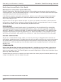
5.3 Dimensions (g. 3 , page 2)
Ref. Dimension
A 83 mm (3.25 in.)
B 83 mm (3.25 in.)
3
Ref. Dimension
C 51 mm (2 in.) clearance behind wall
D 10 mm (0.38 in.)
Maximum relay rating for 12 or 24 V DC discharge pump: 20 amps.
Float Switch Rating: 20 watts with resistive load (when used with DTM04 system).

8
Dometic Tank Discharge ControlInstallation
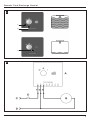
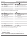
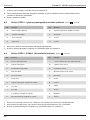
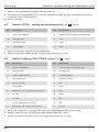
7.1 OPTION 1: DTD01 discharge control panel only (g. 4 , page 3)
1. When boat is in unrestricted waters and pump-out is desired, insert key into switch and turn to
momentary “Start” position (1).
2. Allow key to rebound to “Pump On” position (2). Green light indicates that pump is running.
3. When pump-out is complete, turn key to “Off” position (3) and remove key from switch.
4
7 Operation
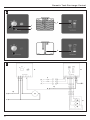
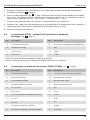
6.3 Key to DTD01-DTM04 system wiring (g. 7 , page 4)
Ref. Description
A DTD01 control panel
B Discharge pump
C DTM04 indicator panel
D Wastewater tank
E 12 or 24 V DC
F V DC ground
G Discharge pump circuit breaker or fuse
H 12 V DC
I 24 V DC
J 1-amp circuit breaker or fuse
K Toilet system circuit breaker or fuse
7
Ref. Description
L + V DC to electric toilet system
M Full level probe
N Mid level probe
O Low/Empty level probe
P Red
Q Black
R Brown
S Green
T Blue
U Yellow
V Orange
6.2 Key to DTD01 - discharge pump system wiring (g. 5 , page 3)
Ref. Description
A DTD01 control panel
B Discharge pump
C 12 or 24 V DC
D V DC ground
5
Ref. Description
E Discharge pump circuit breaker or fuse
F Red
G Black
H Brown
1. Use 14 gauge or larger diameter standard copper wire.
2. Maximum discharge pump circuit breaker or fuse rating: 20 amps.
1. Heavy line indicates 14 gauge or larger stranded copper wire is required.
2. Other wire can be 18 gauge stranded copper wire or larger.
3. Maximum discharge pump circuit breaker or fuse rating: 20 amps.

9
Dometic Tank Discharge Control Warranty and Product Liability
7.2 OPTION 2: DTD01 discharge control panel with DTM04 tank monitor system
(g. 6 , page 4)
1. When the Dometic Tank Monitor panel reads “Full” (3) and boat is in unrestricted waters, insert key
into switch and turn to momentary “Start” position (1).
2. Allow key to rebound to “Pump On” position (2). Green light indicates that pump is running.
3. When pump-out is complete and Tank Monitor panel reads “Empty” (4), pump will automatically
shut off and green light will shut off. Turn key to “Off” position and remove key from switch any time
after pump-out is complete to secure pump.
6
Caution!
Do not allow discharge pump to operate for an extended period of time when there is no
discharge from holding tank. Damage to pump may result.
Europe:
Warranty and Customer Service
Warranty arrangements are in accordance with EC Directive 44/1999/CE and the normal conditions
applicable for the country concerned. For warranty or other service, please contact our Dometic/
Waeco Service department listed elsewhere in this manual. Any damage due to improper use is not
covered by the warranty.
The warranty does not cover any modications to the product or the use of non-original Dometic parts;
the warranty does not apply if the installation and operating instructions are not adhered to and no
liability shall be entertained.
Product Liability
Product liability of Dometic Group and its subsidiary companies does not include damages which
may arise from: faulty operation; improper alterations or intervention in the equipment; adverse
effects from the environment which may impact the equipment itself or the direct vicinity of the
equipment or persons in the area.
To obtain warranty service, rst contact your local dealer from whom you purchased this product or go
to http://www.dometic.com for a dealer near you.
8 Warranty and Product Liability
Caution!
Operator must know local regulations for emptying a holding tank.

10
Dometic Tank Discharge ControlWarranty and Product Liability
® Registered; ™ Trademark of Dometic Corporation
North America and Rest of the World:
Manufacturer’s One-Year Limited Warranty
Dometic Corporation, Sanitation Division warrants to the original purchaser only that this product, if
used for personal, family or household purposes, is free from defects in material and workmanship for
a period of one year from the date of purchase.
If this Dometic product is placed in commercial or business use, it will be warranted to the original
purchaser only to be free of defects in material and workmanship for a period of ninety (90) days
from the date of purchase.
Dometic reserves the right to replace or repair any part of this product that proves, upon inspection
by Dometic, to be defective in material or workmanship. All labor and transportation costs or charges
incidental to warranty service are to be borne by the purchaser-user.
EXCLUSIONS
IN NO EVENT SHALL DOMETIC BE LIABLE FOR INCIDENTAL OR CONSEQUENTIAL DAMAGES,
FOR DAMAGES RESULTING FROM IMPROPER INSTALLATION, OR FOR DAMAGES CAUSED BY
NEGLECT, ABUSE, ALTERATION OR USE OF UNAUTHORIZED COMPONENTS. ALL IMPLIED WAR-
RANTIES, INCLUDING ANY IMPLIED WARRANTY OF MERCHANTABILITY OR FITNESS FOR ANY
PARTICULAR PURPOSE, ARE LIMITED TO A PERIOD OF ONE YEAR FROM DATE OF PURCHASE.
IMPLIED WARRANTIES
No person is authorized to change, add to, or create any warranty or obligation other than that set
forth herein. Implied warranties, including those of merchantability and tness for a particular purpose,
are limited to one (1) year from the date of purchase for products used for personal, family or house-
hold purposes, and ninety (90) days from the date of purchase for products placed in commercial or
business use.
OTHER RIGHTS
Some states do not allow limitations on the duration of an implied warranty and some states do not
allow exclusions or limitations regarding incidental or consequential damages; so, the above limita-
tions may not apply to you. This warranty gives you specic legal rights, and you may have other rights
which vary from state to state.
To obtain warranty service, rst contact your local dealer from whom you purchased this product or go
to http://www.dometic.com for a dealer near you.

11
Dometic Tank Discharge Control Installation template
8
A
C
H
G
F
B D E

12
Dometic Tank Discharge Control
Installation template

13
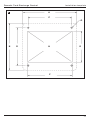
1 Hinweise zur Benutzung der Einbauanleitung..................................... 13
2 Grundlegende Sicherheitshinweise ............................................. 13
3 Vorgesehene Verwendung ................................................ 13 - 14
4 Komponenten ............................................................. 14
5 Spezikationen ........................................................ 14 - 15
6 Installation ............................................................ 15 - 17
7 Bedienung ................................................................ 17
8 Garantie und Produkthaftung ............................................. 17 - 18
1 Hinweise zur Benutzung der Einbauanleitung
Hinweis
Ergänzende Informationen zur Bedienung des Gerätes.
Abb. 1, Seite 2 : Bezeichnet ein Element in einer Illustration. In diesem Beispiel
Element 1 in Abbildung 2 auf Seite 2.
2
Achtung!
Sicherheitshinweis: Nichtbeachtung kann zu Materialschäden führen und die Funktion des
Gerätes beeinträchtigen.
DE
Inhalt
Entsorgungssteuerung Dometic-Tank Hinweise zur Benutzung der Einbauanleitung
2 Grundlegende Sicherheitshinweise
Der Hersteller übernimmt keine Haftung für Schäden aufgrund von
• Montage- oder Anschlussfehlern
• Schäden am Gerät durch mechanische Einwirkung
• Modikationen am Gerät ohne ausdrückliche Genehmigung des Herstellers
• Verwendung für andere als die in der Anleitung beschriebenen Zwecke
3 Vorgesehene Verwendung
3.1 OPTION 1: Nur Bedienfeld für Entsorgungssteuerung DTD01
Auf dem DTD-Bedienfeld für die Tankentsorgungssteuerung bendet sich ein Schlüsselschalter, mit
dem eine Absaugpumpe zur Leerung eines Schmutzwassertanks eingeschaltet wird. Das DTD01 kann
mit praktisch jeder elektrischen Absaugpumpe verwendet werden, die mit derselben Nennspannung
arbeitet (12 V DC oder 24 V DC).
3.2 OPTION 2: Bedienfeld für Entsorgungssteuerung DTD01 mit
Tanküberwachungssystem DTM04
In Verbindung mit dem Tanküberwachungssystem Dometic DTM04 schaltet das DTD-Bedienfeld für die
Tankentsorgungssteuerung die Absaugpumpe automatisch ab, wenn der Schmutzwassertank leer ist.

14
Entsorgungssteuerung Dometic-TankVorgesehene Verwendung
4 Komponenten
Teile in Abb.
. , Seite 2
Beschreibung Artikelnummer (Europa / Nordamerika)
1 Ersatzschlüssel 860003853110362 / 385311036
2 Schlüsselbaugruppe 860003853116104 / 385311610
3 Bedienfeldabdeckung 860003853116112 / 385311611
4 Nr.6 Befestigungselement 860003853116120 / 385311612
5 Montagerahmen 860003853116138 / 385311613
6 Schaltkreisbaugruppe
860003853116146 / 385311614 – 12 V DC
860003853116153 / 385311615 – 24 V DC
7
Gehäuse für
Schaltkreisbaugruppe
860003853116161 / 385311616
1
5 Spezifikationen
5.1 Materialien
3.3 Merkmale
Sichere Absaugpumpensteuerung. Bequeme Möglichkeit zur Absicherung des Absaugpumpenb-
etriebs ohne Vorhängeschloss oder andere mechanische Befestigungsmittel dank Schlüsselschalter.
Hilft, ein Heißlaufen der Pumpe zu vermeiden. Aktivierte Bedienfeldleuchte signalisiert den Betrieb
der Absaugpumpe. Erinnert den Bediener daran, die Pumpe abzuschalten, wenn die Entleerung des
Tanks abgeschlossen ist.
Automatische Pumpenabschaltung in Verbindung mit dem Tanküberwachungssystem DTM04.
Die Absaugpumpe stoppt, wenn der Tankfüllstand unter die Füllstandsmarke “Leer” fällt.
(Abb. 4, Seite 4)
Vereinfacht das Rohrleitungssystem. Vermeidet Y-Ventile, Flutventile und Entlüftungsbögen bei
Systemen mit mehreren Toiletten.
Bedienfeldrahmen und Montagerahmen: ABS Bedienfeldoberfläche: Polycarbonatharz
Gehäuse für Schaltkreisbaugruppe: Hochdruck-Polyethylen
6
Achtung!
Der Betreiber muss die örtlichen Bestimmungen zum Leeren eines
Schmutzwassertanks beachten.

15
6 Installation
1. Wählen Sie den Einbauort des Bedienfelds so, dass
es nicht direkt mit Wasser oder Öl in Berührung
kommen kann.
2. Stellen Sie sicher, dass hinter Wand, Verkleidung oder
Schott Raum für Kabelverbindungen vorhanden ist.
3. Verwenden Sie die Bedienfeld-Schablone (Abb. ,
Seite 11), um das Loch für das Bedienfeld auszusch-
neiden und die Befestigungslöcher zu bohren.
4. Legen Sie bei ausgeschalteter Stromversorgung eine
Kupferlitze mit einem Querschnitt von 2,5 mm2 von
der Stromquelle über einen Leistungsschalter oder
eine Sicherung (nicht im Lieferumfang enthalten)
zum Einbauort des Bedienfelds. Verlegen Sie weitere
Kabel gemäß dem Schaltplan auf Seite 3 oder 4 (siehe
Schlüssel zu Schaltplänen unten) und entsprechend
Ihrem Anwendungsfall zum Einbauort des Bedienfelds.
Längen Sie die Kabel so ab, dass ihre Enden aus dem
Loch für das Bedienfeld herausragen.
6.1 Bedienfeld für Tankentsorgungssteuerung (Abb. 2 , Seite 2)
Abmessungen der Bedienfeld-
Schablone (Abb. , Seite 11)
2
Entsorgungssteuerung Dometic-Tank Spezifikationen
Achtung!
Installieren Sie das DTD-Bedienfeld nicht in Bereichen mit potenziell entflammbaren
oder explosiven Dämpfen.
Ref. Abmessungen
A 83 mm (3,25 Zoll)
B 83 mm (3,25 Zoll)
C 67 mm (2,63 Zoll)
D 67 mm (2,63 Zoll)
E 55 mm (2,16 Zoll)
F 68 mm (2,69 Zoll)
G 2 mm (0,10 Zoll) Durchmesser
H
51 mm ( 2 Zoll) Mindestabstand
hinter Wand
Systemspannung Pumpe aus (A) Pumpe ein (A)
12 V DC 0 0,16
24 V DC 0 0,095
8
8
5.2 Stromaufnahme (nur Bedienfeld)
ISO 8846; EMV-Richtlinie 2004/108/EG
5.4 Zulassungen
5.3 Abmessungen (Abb. 3 , Seite 2)
Ref. Abmessungen
A 83 mm (3,25 Zoll)
B 83 mm (3,25 Zoll)
3
Ref. Abmessungen
C 51 mm (2 Zoll) Mindestabstand hinter Wand
D 10 mm (0,38 Zoll)
Technische Daten können ohne vorherige Ankündigung geändert werden. Maximaler Relais-Schalt-
strom für Absaugpumpe 12 V oder 24 V DC: 20 A. Schwimmerschalter-Nennwert: 20 Watt mit ohmscher
Last (bei Verwendung mit DTM04-System).

16
Entsorgungssteuerung Dometic-TankInstallation
6.3 Legende zum Schaltplan DTD01-DTM04 (Abb. 7 , Seite 4)
Ref. Beschreibung
A DTD01-Bedienfeld
B Abwasserpumpe
C Anzeigefeld DTM04
D Schmutzwassertank
E 12 oder 24 V DC
F V DC Masse
G
Leistungsschalter oder Sicherung
für Absaugpumpe
H 12 V DC
I 24 V DC
J 1-A-Leistungsschalter oder -Sicherung
K
Leistungsschalter oder Sicherung für
Toilettensystem
7
Ref. Beschreibung
L + V DC zum elektrischen Toilettensystem
M Füllstandssonde Voll
N Füllstandssonde Mittel
O Füllstandsonde Niedrig/Leer
P rot
Q schwarz
R braun
S grün
T blau
U gelb
V orange
6.2 Legende zurm Schaltplan des Absaugpumpsystems DTD01 (Abb. , Seite 3)
Ref. Beschreibung
A DTD01-Bedienfeld
B Abwasserpumpe
C 12 oder 24 V DC
D V DC Masse
5
Ref. Beschreibung
E
Leistungsschalter oder Sicherung
für Absaugpumpe
F rot
G schwarz
H braun
1. Kupferlitze mit einem Querschnitt von mindestens 2,5 mm
2
verwenden.
2. Maximaler Nennwert für Leistungsschalter oder Sicherung Absaugpumpe: 20 A.
5. Verbinden Sie die Enden fest mit den Enden der Kabel, die aus der Unterseite der Schaltkreisbau-
gruppe herausragen (Abb. 4, Seite 2).
6. Entfernen Sie die Abdeckung des Bedienfelds (Abb. 1, Seite 2) vom Montagerahmen (2), indem
Sie die beiden Teile vorsichtig auseinanderziehen. Achten Sie darauf, dass die Verbindungen der
Kabel zwischen Schlüsselschalter (3) und Schaltkreisbaugruppe (4) erhalten bleiben. (Schlüssel-
kontakt 1 – rot; Kontakt 2 – braun; Kontakt 7 – blau)
7. Bringen Sie den Montagerahmen mit vier Schrauben (5) an der Wand an.
8. Stecken Sie die Kabel vom Schlüsselschalter in das Baugruppengehäuse und drücken sie die
Bedienfeldabdeckung auf den Montagerahmen, bis sie einrastet.
9. Schalten Sie die Stromversorgung ein.
2
2

17
Entsorgungssteuerung Dometic-Tank Installation
7.2 OPTION 2: Bedienfeld für Entsorgungssteuerung DTD01 mit Tanküberwac-
hungssystem DTM04 (Abb. , Seite 4)
1. Wenn der Dometic-Tankmonitor „Voll“ (3) anzeigt, sich Ihr Boot in freiem Gewässer bendet und Sie
das Schmutzwasser abpumpen möchten, stecken Sie den Schlüssel in den Schalter und drehen ihn
kurz in die Stellung „Start“ (1).
2. Lassen Sie den Schlüssel in die Stellung „Pump On“ (2) zurückfedern. Eine grüne Leuchte zeigt an,
dass die Pumpe läuft.
3. Wenn der Tank leergepumpt ist und der Tankmonitor„Leer“ (4) anzeigt, schaltet sich die Pumpe
automatisch ab und die grüne Leuchte erlischt. Drehen Sie den Schlüssel nach dem Ab-
pumpen jedes Mal in die Stellung „Off“ und ziehen Sie den Schlüssel aus dem Schalter, um
die Pumpe abzusichern.
6
7.1 OPTION 1: Nur Bedienfeld für Entsorgungssteuerung DTD01 (Abb. , Seite 3)
1. Wenn sich Ihr Boot in freiem Gewässer bendet und Sie das Schmutzwasser abpumpen möchten,
stecken Sie den Schlüssel in den Schalter und drehen ihn kurz in die Stellung „Start“ (1).
2. Lassen Sie den Schlüssel in die Stellung „Pump On“ (2) zurückfedern. Eine grüne Leuchte zeigt an,
dass die Pumpe läuft.
3. Wenn der Tank leergepumpt ist, drehen Sie den Schlüssel in die Stellung „Off“ (3) und ziehen den
Schlüssel aus dem Schalter.
4
Achtung!
Lassen Sie die Pumpe nicht längere Zeit bei leerem Schmutzwassertank laufen. Dies
könnte zu Schäden an der Pumpe führen.
7 Bedienung
Europa:
Garantie und Kundendienst
Die Garantievereinbarungen entsprechen der EG-Direktive 44/1999/EG und die normalen Bedingun-
gen gelten für das betreffende Land. Wenden Sie sich an die Dometic/Waeco Service-Abteilung, deren
Adresse Sie an anderer Stelle in diesem Handbuch nden, wenn Sie einen Garantiefall oder eine andere
Serviceleistung vereinbaren möchten. Alle Schäden aufgrund falscher oder missbräuchlicher Bedienung
werden von der Garantie nicht abgedeckt.
Von der Garantie werden keine Änderungen am Produkt oder die Verwendung von anderen Bauteilen als
den Dometic Originalteilen abgedeckt; die Garantie gilt nicht, wenn die Installations- oder Betriebsan-
weisungen nicht beachtet werden. In solchen Fällen wird jedwede Haftung durch den Hersteller abgelehnt.
8 Garantie und Produkthaftung
Achtung!
Der Betreiber muss die örtlichen Bestimmungen zum Leeren eines
Schmutzwassertanks beachten.
1. Dicke Linie steht für Kupferlitze mit Querschnitt von mindestens 2, 5 mm
2
.
2. Der Querschnitt der übrigen Litzen muss mindestens 1 mm
2
betragen.
3. Maximaler Nennwert für Leistungsschalter oder Sicherung Absaugpumpe: 20 A.

18
Entsorgungssteuerung Dometic-TankGarantie und Produkthaftung
Produkthaftung
Die Produkthaftung der Dometic Group und ihrer Niederlassungen umfasst keine Schäden, die
durch das Folgende entstehen: fehlerhafter Betrieb; ungeeignete Änderungen oder Eingriffe in die
Anlage; negative Umgebungsauswirkungen, die die Anlage selbst beeinträchtigen oder die direkte
Umgebung der Anlage oder Personen in diesem Bereich.
Wenn Sie eine Garantieleistung in Anspruch nehmen möchten, wenden Sie sich zuerst an Ihren
Fachhändler vor Ort, bei dem Sie das Produkt erworben haben oder informieren Sie sich im
Internet unter http://www.dometic.com über Händler in Ihrer Nähe.
® Eingetragenes ™ Warenzeichen der Dometic Corporation

19
1 Remarques concernant ce mode d'emploi ....................................... 19
2 Consignes générales de sécurité .............................................. 19
3 Usage conforme ....................................................... 19 - 20
4 Composants .............................................................. 20
5 Spécications ......................................................... 20 - 21
6 Installation ............................................................ 21 - 23
7 Fonctionnement............................................................ 23
8 Garantie et Responsabilité pour le produit ................................... 23 - 25
1 Remarques concernant ce mode d'emploi
Remarque
Informations supplémentaires relatives à l'utilisation de l'appareil.
fig. 1, page 2 : Ceci désigne un élement d'un schéma. Dans cet exemple, l'item 1 du
schéma 2 sur la page 2.
2
Attention !
Consigne de sécurité : Le non-respect de cette consigne peut entraîner des dégâts
matériels et entraver le fonctionnement de l'appareil.
FR
Table des matières
Commande d'évacuation du réservoir Dometic Remarques concernant ce mode d'emploi
2 Consignes générales de sécurité
Le fabricant ne saurait être tenu responsable dans les cas suivants:
• Assemblage ou connections incorrects
• Appareil endommagé par des inuences mécaniques
• Modication de l'appareil sans l'autorisation écrite expresse du fabricant
• Utilisations autres que celles décrites dans le mode d'emploi
3 Usage conforme
3.1 OPTION 1 : panneau de commande d'évacuation DTD01 uniquement
Le panneau de commande d'évacuation du réservoir DTD fournit un commutateur à clé permettant
d'activer une pompe d'évacuation qui vide le réservoir d'eaux usées. Le DTD01 peut a priori être utilisé
avec toutes les pompes électriques d'évacuation fonctionnant avec la même tension nominale (12 V CC
ou 24 V CC).
3.2 OPTION 2 : panneau de commande d'évacuation DTD01 avec système de
surveillance du réservoir DTM04
S'il est combiné avec le système de surveillance du réservoir Dometic DTM04, le panneau de
commande d'évacuation du réservoir DTD éteint automatiquement la pompe d'évacuation lorsque
le réservoir d'eaux usées est vide.

20
Commande d'évacuation du réservoir DometicUsage conforme
4 Composants
Items dans la fig.
, page 2
Description
Numéro d'article
(Europe / Amérique du Nord)
1 Double de clé 860003853110362 / 385311036
2 Assemblage du commutateur 860003853116104 / 385311610
3 Cache du panneau 860003853116112 / 385311611
4 Dispositif de xation n° 6 860003853116120 / 385311612
5 Cadre de montage 860003853116138 / 385311613
6 Assemblage du circuit
860003853116146 / 385311614 – 12 V CC
860003853116153 / 385311615 – 24 V CC
7
Bâti de l'assemblage
du circuit
860003853116161 / 385311616
1
5 Spécifications
5.1 Matériaux
3.3 Fonctions
Commande sécurisée de la pompe d'évacuation. Le commutateur à clé fournit des moyens pra-
tiques de sécuriser le fonctionnement de la pompe d'évacuation sans utiliser de cadenas ou d'autres
éléments mécaniques de xation.
Permet d'éviter une surchauffe de la pompe. L'activation du témoin lumineux du panneau indique le
fonctionnement de la pompe. Cela rappelle à l'opérateur d'éteindre la pompe lorsque la vidange du
réservoir est terminée.
Extinction automatique de la pompe avec le système de surveillance du réservoir DTM04. La
pompe d'évacuation s'arrête lorsque le niveau du réservoir passe en dessous le détecteur de niveau
“Vide” (g. 6 4, page 4).
Simplifie le système de tuyauterie. Plus besoin de vannes en étoiles, de robinets et de boucles de
ventilation présents dans de nombreux systèmes de toilettes.
Cadre du panneau et cadre de montage: ABS
Surface du panneau : résine polycarbonate
Bâti de l'assemblage du circuit : polyéthylène haute densité
6
Attention!
L'opérateur se doit de connaître les réglementations locales concernant la vidange des
réservoirs d'eaux usées.
Seite wird geladen ...
Seite wird geladen ...
Seite wird geladen ...
Seite wird geladen ...
Seite wird geladen ...
Seite wird geladen ...
Seite wird geladen ...
Seite wird geladen ...
Seite wird geladen ...
Seite wird geladen ...
Seite wird geladen ...
Seite wird geladen ...
Seite wird geladen ...
Seite wird geladen ...
Seite wird geladen ...
Seite wird geladen ...
Seite wird geladen ...
Seite wird geladen ...
Seite wird geladen ...
Seite wird geladen ...
Seite wird geladen ...
Seite wird geladen ...
Seite wird geladen ...
Seite wird geladen ...
Seite wird geladen ...
Seite wird geladen ...
Seite wird geladen ...
Seite wird geladen ...
Seite wird geladen ...
Seite wird geladen ...
Seite wird geladen ...
Seite wird geladen ...
Seite wird geladen ...
Seite wird geladen ...
Seite wird geladen ...
Seite wird geladen ...
Seite wird geladen ...
Seite wird geladen ...
Seite wird geladen ...
Seite wird geladen ...
Seite wird geladen ...
Seite wird geladen ...
Seite wird geladen ...
Seite wird geladen ...
Seite wird geladen ...
Seite wird geladen ...
Seite wird geladen ...
Seite wird geladen ...
Seite wird geladen ...
Seite wird geladen ...
Seite wird geladen ...
Seite wird geladen ...
-
 1
1
-
 2
2
-
 3
3
-
 4
4
-
 5
5
-
 6
6
-
 7
7
-
 8
8
-
 9
9
-
 10
10
-
 11
11
-
 12
12
-
 13
13
-
 14
14
-
 15
15
-
 16
16
-
 17
17
-
 18
18
-
 19
19
-
 20
20
-
 21
21
-
 22
22
-
 23
23
-
 24
24
-
 25
25
-
 26
26
-
 27
27
-
 28
28
-
 29
29
-
 30
30
-
 31
31
-
 32
32
-
 33
33
-
 34
34
-
 35
35
-
 36
36
-
 37
37
-
 38
38
-
 39
39
-
 40
40
-
 41
41
-
 42
42
-
 43
43
-
 44
44
-
 45
45
-
 46
46
-
 47
47
-
 48
48
-
 49
49
-
 50
50
-
 51
51
-
 52
52
-
 53
53
-
 54
54
-
 55
55
-
 56
56
-
 57
57
-
 58
58
-
 59
59
-
 60
60
-
 61
61
-
 62
62
-
 63
63
-
 64
64
-
 65
65
-
 66
66
-
 67
67
-
 68
68
-
 69
69
-
 70
70
-
 71
71
-
 72
72


Dometic DTD01 Tank Discharge Control Installationsanleitung
- Typ
- Installationsanleitung
- Dieses Handbuch eignet sich auch für
in anderen Sprachen
- français: Dometic DTD01 Tank Discharge Control Guide d'installation
- español: Dometic DTD01 Tank Discharge Control Guía de instalación
- italiano: Dometic DTD01 Tank Discharge Control Guida d'installazione
- Nederlands: Dometic DTD01 Tank Discharge Control Installatie gids
- dansk: Dometic DTD01 Tank Discharge Control Installationsvejledning
- svenska: Dometic DTD01 Tank Discharge Control Installationsguide
Verwandte Artikel
-
Dometic DTM04 Bedienungsanleitung
-
-
-
-
-
-
-
Dometic Masterflush MF7200 Bedienungsanleitung
-
-