Lutz B4/GT-750 Operating Instructions Manual
- Kategorie
- Spielzeuge
- Typ
- Operating Instructions Manual

Vor Inbetriebnahme Betriebsanleitung lesen!
Read this operating instructions before start up!
Für künftige Verwendung aufbewahren.
To be retained for future reference.
Originalbetriebsanleitung 3–6
MOTOR B4/GT
Operating Instructions
7–10
MOTOR B4/GT
DE
GB

Bild / Fig.1
Bild / Fig.2
Bild / Fig.3

3
DE
Inhaltsverzeichnis
1. Allgemeines....................................................................................... 4
1.1 Lieferumfang .............................................................................. 4
1.2 Baujahr ...................................................................................... 4
2. Motorvarianten .................................................................................. 4
3. Inbetriebnahme ................................................................................. 5
3.1 Montage im Behälter .................................................................. 5
3.2 Netzanschluss ............................................................................ 5
3.3 Drehrichtungskontrolle ................................................................ 5
3.4 Montage am Pumpwerk .............................................................. 5
3.5 Entlüftungsventil montieren ........................................................ 5
3.6 Maximale Eintauchtiefe ............................................................... 5
3.7 Unerwarteter Anlauf der Pumpe nach Spannungsabfall ................. 5
4. Wartung ............................................................................................ 5
5. Reparaturen ...................................................................................... 5
EG-Einbauerklärung ........................................................................... 11

4
DE
Allgemeine Sicherheitshinweise
Die Betriebsanleitung ist vor Inbetriebnahme vom Be-
diener des Motors zu lesen und die Hinweise sind
während des Betriebs einzuhalten.
1. Die Antriebseinheit B4/GT ist nicht explosionsgeschützt.
Sie besteht aus einem Antriebsmotor mit angebautem
Getriebe und darf nicht in explosionsgefährdeter Umgebung
eingesetzt werden.
2. Die komplette Antriebseinheit eignet sich auch nicht für
den Einsatz im explosionsgefährdetem Bereich, wenn ein
explosionsgeschützter Motor an das Getriebe angebaut
wird.
3. Es dürfen keine brennbaren Flüssigkeiten gefördert wer-
den.
4. Die bestimmungsgerechte Gebrauchslage des Motors ist
senkrecht.
5. Die auf dem Typenschild aufgeführte Spannung muss mit
der Netzspannung übereinstimmen.
6. Prüfen Sie ob der Motor ausgeschaltet ist, bevor Sie die
elektrische Verbindung herstellen.
7. Beachten Sie, dass alle Anschlüsse und Verbindungen
richtig befestigt sind.
8. Vor Inbetriebnahme Verschlussstopfen gegen Entlüftungs-
ventil austauschen.
9. Motor nicht ohne Pumpwerk betreiben.
10. Der Motor darf nicht in die Förderflüssigkeit getaucht wer-
den.
11. Instandsetzung nur durch den Hersteller.
Die Unfallverhütungsvorschriften des jeweiligen Landes sind
unbedingt einzuhalten.
1. Allgemeines
Eine elektrische Fass- und Behälterpumpe besteht aus dem
Motor und einem zum jeweiligen Einsatzfall passenden Pump-
werk. An den Motor ist ein einstufiges Getriebe angeflanscht.
Das Getriebe ist ölgeschmiert.
Der Motortyp B4/GT-750 mit den verschiedenen Pumpwerken
eignet sich zum Pumpen nichtbrennbarer, aggressiver, dünn-
flüssiger bis mittelviskoser Medien.
1.1 Lieferumfang
Prüfen Sie die Lieferung mit Hilfe Ihrer Bestellung auf Voll-
ständigkeit.
1.2 Baujahr
Das Baujahr des Gerätes ist aus dem Feld für die Seriennummer
ersichtlich. Dort sind mit einem Bindestrich die letzten beiden
Stellen des Baujahrs an die Seriennummer angehängt (z.B.
-10 für das Jahr 2010).
2. Motorvarianten
Die Motoren der Baureihe B4/GT sind Drehstromgetriebemo-
toren in Betriebsspannung, Leistung und Frequenz gemäß
Tabelle 1 (siehe Seite 6). Spannung und Frequenz sind auf
Übereinstimmung mit dem vorhandenen Netz zu prüfen.
Der Bediener ist Vibrationen ausgesetzt, wenn er den Motor
während des Betriebs in der Hand hält. Die Beschleunigung,
der die oberen Körpergliedmaßen ausgesetzt sind, liegt unter
2,5 m/s².

5
DE
3. Inbetriebnahme
3.1 Montage im Behälter
Befestigen Sie die Pumpe mit geeigneten Fassadaptern im
Behälter. Achten Sie darauf, dass der Behälter auch in leerem
Zustand mit der eingebauten Pumpe standsicher ist. Dies gilt
besonders bei kleinen Gefäßen.
3.2 Netzanschluss
Wir empfehlen dem Motor einen der Stromaufnahme entspre-
chenden Schutzschalter vorzuschalten, um einer Zerstörung
des Motors durch Überlastung vorzubeugen.
Der elektrische Anschluss darf nur durch geschultes
Fachpersonal erfolgen. Dabei sind folgende Bedin-
gungen einzuhalten:
- Alle Arbeiten im spannungslosen Zustand des Motors
vornehmen.
Wenn vorhanden, angebauten Schutzschalter in Aus-Stellung
bringen.
- Netzspannung und Frequenz müssen mit den Angaben auf
dem Typenschild übereinstimmen.
- Abmessung des Anschlusskabels muss dem Nennstrom
angepasst werden.
- Die Isolierung des Anschlusskabels muss den
Umgebungsbedingungen angepasst sein.
3.3 Drehrichtungskontrolle
Nach Einschalten des Motors muss die Drehrichtung der An-
triebswelle mit dem Drehrichtungspfeil auf dem Typenschild
übereinstimmen. Gegebenenfalls ist der Motor umzuklem-
men.
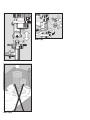
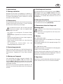
3.4 Montage am Pumpwerk
Der Pumpenmotor wird auf das Pumpwerk aufgesetzt. Hier-
bei greift der Mitnehmer (Bild 1- Pos. 1) am Motor in die
Kupplung (Bild 1 - Pos. 2) am Pumpwerk ein. Nun werden
mit dem Handrad (Rechtsgewinde) Motor und Pumpwerk fest
miteinander verbunden.
Beim Einsatz von Kunststoff-Pumpwerken empfehlen wir, das
Pumpwerk vom Gewicht des Motors durch eine Halterung zu
entlasten.
3.5 Entlüftungsventil montieren
Vor Inbetriebnahme der Pumpe Verschlussstopfen (Bild 2 -
Pos. 1) gegen Entlüftungsventil (Bild 2 - Pos. 2) austauschen.
Danach dürfen Sie den Motor nicht mehr waagrecht oder in
Schräglage ≥ 15° betreiben oder aufbewahren, da sonst Öl
austreten kann.
3.6 Maximale Eintauchtiefe
Es muss gewährleistet sein, dass die Pumpe nicht tiefer als bis
zum Auslaufstutzen eintaucht (siehe Bild 3).
3.7 Unerwarteter Anlauf der Pumpe nach
Spannungsabfall
Der Motor ist nicht mit einer Unterspannungsauslösung
ausgerüstet.
Nach einem Spannungsabfall kann die Pumpe uner-
wartet anlaufen.
4. Wartung
Nach 500 Betriebsstunden:
Ölstand im Getriebe prüfen. Dazu befindet sich ein Ölschauglas
über dem Typenschild.
Bei Ölmangel Getriebeöl ESSO HDX oder gleichwertiges Öl HD
SAE 20 nachfüllen.
Nach 1000 Betriebsstunden:
Getriebeöl auswechseln. 0,2 l Getriebeöl ESSO HDX oder gleich-
wertiges Öl HD SAE 20 verwenden.
Schützen Sie die Umwelt: Handhabung und Entsorgung von
Mineralölen unterliegen gesetzlichen Regelungen. Liefern Sie
Altöl bei einer autorisierten Annahmestelle ab.
5. Reparaturen
Reparaturen nur vom Hersteller oder autorisierten Vertragswerk-
stätten ausführen lassen. Nur Lutz-Ersatzteile verwenden.

6
DE
Tabelle 1
Typ Spannung Frequenz Leistung Schutzart Schall-
druck-
pegel
1)
Gewicht Bestell-Nr.
B4/GT-750 230/400 V 50 Hz 750 W IP 55 77 dB(A) 10 kg 0004+019
B4/GT-750 230/400 V 50 Hz 750 W IP 54,
mit Schutzschalter
77 dB(A) 10 kg 0004+067
1)
Gemessen mit voll gedrosseltem Pumpwerk Niro 41-R, Messabstand 1m

7
GB
Table of Contents
1. General ............................................................................................. 8
1.1 Scope of supply .......................................................................... 8
1.2 Year of construction .................................................................... 8
2. Motor types ....................................................................................... 8
3. Starting up ........................................................................................ 9
3.1 Assembly in the container ........................................................... 9
3.2 Mains connection ....................................................................... 9
3.3 Checking the direction of rotation ................................................ 9
3.4 Connection to the pump tube ...................................................... 9
3.5 Mounting the vent valve ............................................................. 9
3.6 Maximum immersion depth ......................................................... 9
3.7 Uncontrolled re-start of the pump after voltage drop ..................... 9
4. Maintenance ..................................................................................... 9
5. Repairs ............................................................................................. 9
EC Declaration of Incorporation ........................................................... 11

8
GB
General safety information
The operator must read and follow the operating
instructions before starting the motor.
1. The drive unit B4/GT is not explosion proof. It is consisting
of a drive motor with attached gear and is not allowed to
be used in explosion hazard areas.
2. The complete drive unit is not suitable for being used in
explosion hazard areas even if an explosionproof drive
motor is attached onto the gear.
3. The motor must not be used to pump flammable liquids.
4. The motor may only be operated in an upright position.
5. The voltage specified on the rating plate must match that
provided by the mains supply.
6. Ensure that the motor is switched off before connecting to
the electricity supply.
7. Ensure that all connections and fittings are properly
tightened.
8. Before starting up the pump, replace screw plug by vent
valve.
9. Do not operate motor without pump tube.
10. The motor must not be immersed in the liquid being
pumped.
11. Repairs may only be carried out by the manufacturer.
The national accident prevention regulations must be observed
without fail.
1. General
An electric drum and container pump comprises motor and
pump tube to suit the particular application. A single-stage gear
is flanged onto the motor. The gear is oil-lubricated.
Motor type B4/GT-750 with the various pump tubes is suitable
for pumping non-flammable, aggressive, thin-bodied up to
medium viscous liquids.
1.1 Scope of supply
Check that the consignment is complete as ordered.
1.2 Year of construction
The year of construction of the appliance can be seen on the
field for the serial number. Here are attached to the serial
number the both last digits of the year of construction, e.g.
(-10 for the year 2010).
2. Motor types
The motors of series B4/GT are three-phase gear motors with
operating voltage, rating and frequency specified according to
table 1 (see page 10). Check that the specified voltage and
frequency match the available mains supply.
Vibrations are transmitted to the operator as he holds the motor
in his hand during operation. The upper limbs are exposed to
an acceleration of less than 2.5 m/s².

9
GB
3. Starting up
3.1 Assembly in the container
Fasten the pump in the container with appropriate drum ad-
apters. Make sure that the container with the installed pump
is enough stably even in empty condition. This is of special
attention with small containers.
3.2 Mains connection
It is recommended to provide the motor with a protection switch
corresponding to the power consumption so as to prevent motor
destruction by overloading.
The electrical connection may only be carried out by
trained qualified personnel. Following regulations must
be observed:
- All works must only be carried out in voltage-free condition
of the motor.
If available, set the protection switch mounted to OFF.
- Mains voltage and frequency are as specified on the rating
plate.
- Dimension of the connecting cable must be adjusted to the
nominal current.
- The insulation of the connecting cable must be adjusted to
the environmental conditions.
3.3 Checking the direction of rotation
After the motor has been started, the direction of rotation of
the drive shaft must correspond to the rotation arrow on the
rating plate. If necessary, the motor terminal connections must
be reversed.
3.4 Connection to the pump tube
The motor is mounted on the pump tube. The upper cou-
pling (Fig. 1 - Pos.1) on the motor engaging in the coupling
(Fig. 1 - Pos. 2) of the pump tube. The motor and pump
tube are then firmly connected by means of the handwheel
(right-hand thread).
When using plastic pump tubes, it is recommended to relieve
the pump tube of the motor weight by means of a support.
3.5 Mounting the vent valve
Before starting up the pump, replace screw plug (Fig. 2 –
Pos. 1) by vent valve (Fig. 2 – Pos. 2). Thereafter, the motor
may no more be operated or stored in horizontal or inclined
position ≥ 15° as oil will otherwise leak.
3.6 Maximum immersion depth
Care must be taken to ensure that the pump is not submerged
further than its discharge port (see Fig. 3).
3.7 Uncontrolled re-start of the pump after
voltage drop
The motor is not equipped with a low voltage release.
After a voltage drop the pump may re-start
uncontrolled!
4. Maintenance
After 500 working hours:
Check gear oil level by means of an oil sight-glass situated
above the rating plate.
In case of oil deficiency, top up gear oil ESSO HDX or equivalent
oil HD SAE 20.
After 1000 working hours:
Change gear oil. Use 0.2 l gear oil ESSO HDX or equivalent
oil HD SAE 20.
Protect the environment: Handling and waste disposal of
mineral oils are subject to statutory provisions. Deliver waste
oil to an authorized point of acceptance.
5. Repairs
Repairs should only be made by the manufacturer or authorized
Lutz-dealers. Only use genuine Lutz spare parts.

10
GB
Table 1
Type Voltage Frequency Power Type of protection Sound
pressure
level
1)
Weight Order No.
B4/GT-750 230/400 V 50 Hz 750 W IP 55 77 dB(A) 10 kg 0004+019
B4/GT-750 230/400 V 50 Hz 750 W IP 54,
with protection switch
77 dB(A) 10 kg 0004+067
1)
Measured with fully throttled pump tube stainless steel 41-R, measuring distance 1 m

11
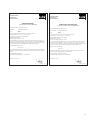
EG-Einbauerklärung
nach Maschinenrichtlinie 2006/42/EG
Hiermit erklären wir, dass das folgende Produkt
Geräteart: Drehstromgetriebemotor
Typ: B4/GT
den folgenden grundlegenden Anforderungen der Richtlinie entspricht:
Anhang I, Artikel 1.1.2, 1.1.3, 1.2.6, 1.3.2, 1.5.1 und 1.7.4
Folgende weitere EU-Richtlinien wurden angewandt:
EMV-Richtlinie 2004/108/EG
Niederspannungsrichtlinie 2006/95/EG
Die Inbetriebnahme dieses Produkts ist so lange untersagt, bis die Maschine oder die Anlage, in
welche dieses Produkt eingebaut werden soll oder von welcher es eine Komponente darstellt, den
Bestimmungen aller relevanten Richtlinien entspricht. Bei Verwendung von Pumpwerken der Firma
Lutz Pumpen GmbH erfüllt die vollständige Maschine die EG-Maschinenrichtlinie.
Angewandte harmonisierte Normen:
EN ISO 12100
Für das Produkt wurden die speziellen technischen Unterlagen gemäß Anhang VII Teil B erstellt, auf
begründetes Verlangen können diese Unterlagen einer einzelstaatlichen Stelle per Post übermittelt
werden.
Dokumentationsbevollmächtigter:
Lutz Pumpen GmbH, Erlenstraße 5-7, D-97877 Wertheim
Wertheim, den 07.11.2013
Jürgen Lutz, Geschäftsführer
Lutz Pumpen GmbH
Erlenstraße 5-7
D-97877 Wertheim
EC Declaration of Incorporation
according to Machinery Directive 2006/42/EC
We herewith declare that the following product
Type of device: Three phase gear motor
Type: B4/GT
fully complies with the following basic requirements of the Directive:
Annex I, Article 1.1.2, 1.1.3, 1.2.6, 1.3.2, 1.5.1 and 1.7.4
Following additional EC Directives were applied:
EMC Directive 2004/108/EC
Directive of low voltage equipment 2006/95/EC
It is not allowed to bring the appliance into service as long as the machine or the system into which
this product shall be incorporated or of which it is a component, does not fully conform with the
requirements of all relevant Directives. The complete machine complies with the provisions of the EC
Directive on machinery safety when pump tubes made by Lutz Pumpen GmbH are used.
Applicable harmonized standards:
EN ISO 12100
Special technical fi les for the product were provided according to Annex VII, Part B. On justifi ed
demand of a national authority these fi les can be sent by post.
Person authorised to compile the technical fi le
Lutz Pumpen GmbH, Erlenstraße 5-7, D-97877 Wertheim
Wertheim, 07.11.2013
Jürgen Lutz, Managing Director
Lutz Pumpen GmbH
Erlenstraße 5-7
D-97877 Wertheim

Technische Änderungen vorbehalten. 11/13
Subject to technical changes. Best.-Nr. 0698-080 Printed in Germany / Dru.
Lutz Pumpen GmbH
Erlenstraße 5 -7
D-97877 Wertheim
Tel. (0 93 42) 8 79-0
Fax (0 93 42) 87 94 04
e-mail: [email protected]
http://www.lutz-pumpen.de
-
 1
1
-
 2
2
-
 3
3
-
 4
4
-
 5
5
-
 6
6
-
 7
7
-
 8
8
-
 9
9
-
 10
10
-
 11
11
-
 12
12


Lutz B4/GT-750 Operating Instructions Manual
- Kategorie
- Spielzeuge
- Typ
- Operating Instructions Manual
in anderen Sprachen
- English: Lutz B4/GT-750
Verwandte Artikel
Andere Dokumente
-
Homa C270 WF Bedienungsanleitung
-
-
MOTO GUZZI V 11 SPORT Workshop Manual
-
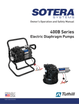 SOTERA SS445B Bedienungsanleitung
-
Cushman SUZUKI 660 K6A Benutzerhandbuch
-
-
APRILIA RS 50 - 1995 Bedienungsanleitung
-
Flux VISCO Lite Bedienungsanleitung
-
