
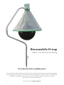
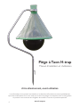
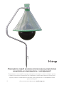
H-TRAP
HORSEFLY CONTROL SYSTEM
English
Deutsch
Français
Nederlands
Español
Pусский
Service Manual
The professional
horsefly control system

English Service manual
Deutsch Gebrauchsanweisung
Français Manuel d’utilisation
Nederlands Installatie handleiding
Español Manual de instrucciones
Pусский Инструкция по применению
3
6
10
14
18
22
Please read carefully, before using your unit!
The information in this service manual is based on the latest information, and is provided
subject to alterations. We reserve the right to change the construction and/or conguration
of the product at any time without obligation to modify earlier versions of the product.
For further data: www.h-trap.net
UK
DE
FR
NL
ES
RU

3
All rights reserved. No part of this document may be reproduced, stored in a database or any other retrieval system, or published, in any form or in
any way, electronically, mechanically, digitally per photo print or microlm or any other way without written permission from the writer. © 2019 Copyright
Alcochem, The Netherlands
Service manual H-trap / English version 3.1
A. Read this manual carefully before taking any action
Congratulations with the purchase of this high quality horse y trap. Before using this model we
would like to ask you to read this manual carefully. If you have questions afterwards feel free to
contact your local supplier.
The information in this manual is based upon the latest information, and is provided subject to
alterations. We reserve the right to change the construction and/or conguration of the product
at any time without obligation to modify earlier versions of the product. Store this manual
carefully for future use.
B. Receipt of unit
While unpacking, check for any signs of shipment damage. If found, notify both your transporter
and supplier in writing, within 8 days after receipt, with full details of the damage that has
occurred. Retain the equipment and packing materials for inspection. Check that all parts have
been received as ordered. Make sure that all packaging is removed from the unit before use.
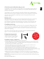
C. Installation of the H-trap
The H-trap needs to be installed in the direct vicinity of the resting and/or feeding places of the
animals, in the ground or against a wall or pole. Horses are especially curious animals and may
want to nibble at the plastic hood. This needs to be avoided . If required, protect the H-trap to
avoid this from happening.
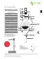
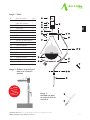
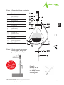
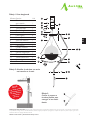
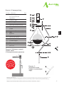
The numbers in the text below refer to the numbers used in the exploded view drawings,
gures 1 to 3, which are placed at the back of this manual.
D. Required mounting materials
• Hammer (not in scope of supply)
• Wrench (2 pieces in scope of supply)
• Pump (1 piece in scope of supply)
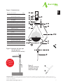
E. Installation: see gure 1 Exploded view
1. Mark the spot in the ground where you want to place the unit.
2. Once the base pipe (1) is rmly placed onto the ground use a hammer to drive the pipe into the
ground, till the anti-rotation anchor is completely under the soil. If the ground is very hard you can
use a ground drill. (not included in scope of supply)
3. Mount the middle pipe (2) onto the base pipe (1) using the long bolt (4) and the nut (5).
For this action the supplied two wrenches (6) can be used.
4. Mount the top pipe (3) onto the middle pipe (2) using the long bolt (4) and the nut (5)
5. Mount the bracket (7) on the top into the top pipe (3) using the long bolt (4) and the nut (5).
6. Make sure that the bracket (7) and stabilising ring (8) are rmly connected with the two M8 (17) bolts.
7. Place the metal holder (11) into the stabilising ring (8) by means of two bolts (17)
8. Inate the ball (9) using a compressed air unit, a pump for an airbed, or use the included pump.
The diameter of the ball must be approx. 60 cm. Put in the white plastic plug after inating the ball.
Attention!!
If the ground
is very hard, please
use a
ground drill
Please read carefully, before using your unit!
The information in this service manual is based on the latest information, and is provided
subject to alterations. We reserve the right to change the construction and/or conguration
of the product at any time without obligation to modify earlier versions of the product.
For further data: www.h-trap.net
UK

4
9. Place the funnel (10) onto the metal holder (11) by means of the Velcro band (12)
10. Lift up the funnel (10) mount the ball (9) on the metal holder (11) using the ball hook (13)
11. Put one side of the pipe connector (14) into the reinforcement pipe (15), see g 3.
12. Insert the reinforcement pipe (15) with the pipe connector (14) into the opening in the lower base
of the funnel (10). If needed, the use of soap to lubricate the pipe will simplify this process. Connect
the other end of the 1st reinforcement pipe to the next pipe connector and continue to thread
through the base of the funnel until all three reinforcement pipes and 3 pipe connectors form into
one round ring.
13. Place the collection tray (16) with the lid closed into the holder (11)
The H-trap is ready for use now.
F. Periodic maintenance
• The collection bin of the horse y trap needs to be checked, (lled with water if necessary)
and emptied regularly.
• Make sure that the ball stays inated.
• Storms and high winds will have an impact on the stability of the H-trap.
Check this periodically or after storms.
• The plug in the ball can be removed with included white plastic plug removal tool
G. Key features
• Galvanised, corrosion proof construction.
• Weather-proof design.
• Easy & fast installation.
• Environmental friendly.
• Ergonomic design, allows easy handling of the trap.
• Effective and easy control of horse ies.
• 2 years warranty on mechanical defects.
H. Key specications
Dimensions : 1.20 m middle diameter, height above the ground ±1.95 m
Colour : black ball & green conical plastic funnel
Material : hot zinc dipped mounting frame, thickness 2.0 mm
Weight : about 15 kg
Tools : manual pump/ Wrench included
Collect tray : 1 included
Packing size : 1130 x 220 x 200 mm

5
All rights reserved. No part of this document may be reproduced, stored in a database or any other retrieval system, or published, in any form or in
any way, electronically, mechanically, digitally per photo print or microlm or any other way without written permission from the writer. © 2019 Copyright
Alcochem, The Netherlands
Service manual H-trap / English version 3.1
15
14
Attention!!
If the ground
is very hard, please
use a
ground drill
5
2
14
4
5
3
11
16
17
12
8
13
7
10
9
4
5
6
4
1
15
Figure 1: Exploded view
Figure 2: Hammer the base pipe
into the ground
(with Anti-rotation anchor)
Figure 3:
Assembly of the pipe
connector onto the
reinforcement pipe
Part no. Part name Qty
1 Base pipe with
Anti-rotation anchor
2 Middle pipe 1
3 Top pipe 1
4 Long bolt 3
5 Nut for long bolt 3
6 Wrench 2
7 Bracket 1
8 Stabilising ring 1
9 Ball 1
10 Funnel 1
11 Metal holder 1
12 Velcro band 1
13 Ball hook 1
14 Pipe connector 3
15 Reinforcement pipe 3
16 Collect tray 1
17 M8 bolt 4
UK

6
Bremsenfalle H-trap
Aufbau- und Gebrauchsanweisung
Vor Gebrauch bitte sorgfältig lesen!
Der Inhalt dieser Gebrauchsanweisung entspricht den neuesten Erkenntnissen und unterliegt ständiger
Überarbeitung. Änderungen der Konstruktion und/oder Konguration dieses Produkts sind ausdrücklich
vorbehalten und gewähren keinen Anspruch auf nachträgliche Anpassung früherer in Verkehr
gebrachter Versionen dieses Produkts.
Mehr Information: www.h-trap.net

7
Alle Rechte vorbehalten. Die Vervielfältigung, Speicherung in Datenspeichern oder jedem anderen System, Veröffentlichung in jedweder Form, sei
es elektronisch, mechanisch, digitalisiert per Foto, Mikrolm oder in jedweder anderen Form auch in Auszügen bedürfen der vorherigen schriftlichen
Einwilligung des Verfassers. © 2019 Copyright Alcochem, Niederlande
Gebrauchsanweisung H-trap / Bremsenfalle deutsche Fassung 3.1
A. Lesen Sie diese Anweisung sorgfältig vor Aufstellung und Gebrauch der Bremsenfalle:
Wir gratulieren Ihnen zum Erwerb dieser hochwertigen Pferdeiegenfalle. Bevor Sie die Bremsenfalle
in Gebrauch nehmen, lesen Sie sich diese Gebrauchsanweisung sorgfältig durch. Bei Fragen wenden
Sie sich bitte an Ihren örtlichen Lieferanten. Der Inhalt dieser Anweisung entspricht den neuesten
Erkenntnissen und wird ständig aktualisiert. Änderungen der Konstruktion und/oder Konguration
dieses Produktes sind ausdrücklich vorbehalten und gewähren keinen Anspruch auf nachträgliche
Anpassung früherer in Verkehr gebrachter Versionen dieses Produkts. Bewahren Sie diese
Gebrauchsanweisung für den späteren /weiteren Gebrauch auf.
B. Lieferung und Empfang der Bremsenfalle:
Achten Sie während des Auspackens auf Transportbeschädigungen jeglicher Art und teilen sie diese dem
Lieferanten unverzüglich mit. Bewahren Sie bitte sowohl das Produkt, als auch das Verpackungsmaterial
für eine mögliche Begutachtung auf. Überprüfen Sie die Vollständigkeit der von Ihnen gekauften Ware.
Entfernen Sie sämtliche Verpackung vor Ingebrauchnahme dieses Produkts.
C. Aufbau der Bremsenfalle:
Positionieren Sie die Falle für maximalen Erfolg in den Flugbahnen der Bremsen zwischen den
bevorzugten Feuchtgebieten (z.B. Teich, Flussufer, etc.), aber auch Wäldern, Kornfeldern usw. und
den geplagten Pferden oder Menschen, tendenziell räumlich näher an den geplagten Opfern. Eine
Bremsenfalle wird für max. 5 Pferde empfohlen. Die Falle sollte kurz vor dem Ausug der weiblichen
Pferdebremsen (ab ca. April) aufgestellt werden. Bei unzureichender Fangquote überprüfen Sie bitte
zuerst den Standort. Stellen Sie sicher, dass Pferde den Schirm nicht anknabbern etc. Schützen Sie die
Bremsenfalle gegebenenfalls mittels einer Einzäunung.
Die nachfolgenden Nummern entsprechen denen der auf der Rückseite dieser Gebrauchs-
anweisung abgebildeten Explosionszeichnung.
D. Benötigte Werkzeuge:
• Hammer (nicht enthalten)
• Luftpumpe (1x enthalten)
• Schraubenschlüssel (2 Stück enthalten)
E. Aufbau: Vorbereitung: Montage Ball und Schirm
1. Pumpen Sie den Ball (9) mittels eines Kompressors oder der beigefügten Pumpe auf. Der
Durchmesser des Balls sollte ca. 60 cm betragen (Umfang ca. 170 cm). Verschließen Sie den Ball
danach mit dem Verschlussstöpsel.
2. Befestigen Sie den Ball (9) an der abgeachten Fläche des Ball-Hakens (13).
3. Stecken Sie ein Ende des Schlauchverbinders (14) in den Verstärkungsschlauch (15),
entsprechend Abb. 3.
4. Verbinden Sie die Verstärkungsschläuche (15) mittels Schlauchverbinder (14) und schieben
Sie diese in die unten am Schirm (10) bendliche Öffnung. Benutzen Sie ggf. Seife, um das
Einführen zu erleichtern. Verbinden Sie nun das andere Ende des Schlauchs mit dem
Schlauchverbinder.
Achtung!!
Wenn der Boden
sehr hart ist,
verwenden Sie
bitte einen
Erdbohrer.
DE

8
Aufbau Metall-Gehäuse
5. Schlagen Sie das Sockelrohr (1) entsprechend Abb. 2. in die Erde. Benutzen Sie eine Wasserwaage,
um den senkrechten Stand der Bremsenfalle zu gewährleisten. Bauen Sie jetzt das Metall-Gehäuse,
wie abgebildet in Abbildung 1 auf Seite 4, auf.
Befestigung von Ball und Trichter an das Metall-Gehäuse
6. Befestigen Sie den Schirm (10) mittels der Klettbänder an der Halterung (11).
7. Befestigen Sie den Ball-Haken (13) mit dem daran hängenden Ball an der Halterung (11).
8. Stecken Sie das Sammelgefäß (16) mit Deckel in die Halterung (11).
Die Bremsenfalle ist nunmehr gebrauchsfertig.
F. Regelmäßige Pege und Wartung:
• Das Sammelgefäß der Fliegenfalle muss regelmäßig überprüft und entleert werden. Falls
erforderlich, muss Seifenwasser nachgefüllt werden.
• Stellen Sie sicher, dass der Ball ständig aufgeblasen ist.
• Sturm und starke Winde beeinussen die Stabilität der Bremsenfalle. Überprüfen Sie diese
Regelmäßig und im Bedarfsfall.
• Der Verschlussstöpsel des Balles kann leicht mittels des beigefügten Werkzeugs
Herausgenommen werden
G. Besondere Produktmerkmale:
• Galvanisierte, korrosionsgeschützte Konstruktion
• Witterungsbeständig
• Verringert die Bremsenpopulation um bis zu 95 %
• Leichter Aufbau
• Umweltfreundlich, ohne Insektizide
• Leichte Handhabung durch ergonomisches Design
• 2 Jahre Garantie auf mechanische Teile
H. Technische Merkmale:
Abmessungen : Mittlerer Durchmesser: 1,20 m, Höhe ab Boden: 1,95 m
Farben : Schwarz (Ball) & Grün (Kunststoff-Schirm)
Material : Feuerverzinkter Rohrrahmen, Wandung: 2.0 mm
Gewicht : ca. 15 kg
Zubehör : Luftpumpe / Schraubenschlüssel
Verpackung : 1130 x 220 x 200 mm

9
Alle Rechte vorbehalten. Die Vervielfältigung, Speicherung in Datenspeichern oder jedem anderen System, Veröffentlichung in jedweder Form, sei
es elektronisch, mechanisch, digitalisiert per Foto, Mikrolm oder in jedweder anderen Form auch in Auszügen bedürfen der vorherigen schriftlichen
Einwilligung des Verfassers. © 2019 Copyright Alcochem, Niederlande
Gebrauchsanweisung H-trap / Bremsenfalle deutsche Fassung 3.1
15
14
Achtung!!
Wenn der Boden sehr
hart ist, verwenden
Sie bitte einen
Erdbohrer.
5
2
14
4
5
3
11
16
17
12
8
13
7
10
9
4
5
6
4
1
15
Abb. 1: Explosionszeichnung
Abb. 2: Detailansichten :
(Sicherungspin zur Verhinderung
von Rotationsbewegungen)
Abb. 3:
Verbindung von
Verstärkungsschlauch
und Schlauchverbindern
Nr
Unterteil St
1 Sockelrohr, Sicherungspin
zur Verhinderung von
Rotationsbewegungen 1
2 Mitte Rohr 1
3 Top Rohr 1
4 Schraube 3
5 Nuss-Schlossschraube 3
6 Schraubenschlüssel 2
7 Befestigungsgabel 1
8 Befestigungsring 1
9 Ball 1
10 Schirm 1
11 Halterung 1
12 Klettbänder 1
13 Ball-Haken 1
14 Schlauchverbinder 3
15 Verstärkungsschlauch 3
16 Sammelgefäß 1
17 M8 Schraube 4
DE

10
Piège à Taon H-trap
Manuel d’installation et d’utilisation
A lire attentivement, avant utilisation
Les informations de ce manuel, sont basées sur les dernières informations, et seront probablement
sujet à des modications. Nous nous réservons le droit de changer la conception et/ou la conguration
du produit à tout moment sans obligation de modier la version du produit auparavant.
www.h-trap.net

11
Tous droits réservés. © 2019 Copyright Alcochem. Sous réserve de modications sans préavis.
Attention!!
Si le sol est
très dur,
veuillez utiliser
une foreuse
A. Lisez ce manuel avec attention avant toute action :
Félicitation pour votre commande de ce piège à taon haute qualité. Avant d’utiliser ce modèle, nous
vous demandons de lire ce manuel attentivement. Si vous avez des questions, n’hésitez pas à nous
contacter.
Les informations de ce manuel, sont basées sur les dernières informations, et seront probablement
sujet à des modications. Nous nous réservons le droit de changer la conception et/ou la
conguration du produit à tout moment sans obligation de modier la version du produit auparavant.
Conservez ce manuel pour vos prochaines utilisations.
B. Réception du matériel :
Pendant le déballage, vérier qu’il n’est pas été abimé lors du transport. Si cela était le cas, le
notier par écrit sous 8 jours. Conservez aussi bien le produit que son conditionnement pour une
éventuelle expertise. Inspectez l’intégrité du produit que vous avez acheté. Eliminez tout objet de
conditionnement avant toute mise en marche de ce produit.
C. Installation du H-trap :
Le H-trap doit être placé sur le sable, contre un mur ou sur pieu, à proximité des endroits de repos
et/ou d’alimentation des animaux. Durant le montage, veillez à ce qu’aucun animal ne puisse grignoter
la boule en plastique. Clôturez le H-trap si besoin.
Les numéros suivants correspondent à ceux de l’éclaté à la n de ce manuel.
D. Outils nécessaires au montage :
• Marteau (non inclus)
• Clé (2 clés incluses)
• Pompe (incluse)
E. Installation (voir éclaté image 1) :
1. Marquer l’emplacement où vous souhaitez installer le H-trap.
2. Placer la base du pied (1) dans le sol, puis l’enfoncer au marteau (voir image 2)
3. Monter le tube central (2) sur le tube de base (1) en utilisant le boulon (4) et l’écrou (5).
Pour cette action, les deux clés fournies (6) peuvent être utilisées
4. Monter le tube supérieur (3) sur le tube central (2) à l’aide du boulon (4), et l’écrou (5).
5. Monter le support (7) sur le tube supérieur (3) en utilisant le boulon (4) l’écrou (5).
6. Vérier que le support (7) et l’anneau de stabilisation (8) sont solidement xés avec les 2
vis M8 (17).
7. Placer le support métallique (11) sur le support de stabilisation (8) à l’aide des deux vis (17)
8. Goner la boule noire (9) en utilisant un compresseur d’air , une pompe pour matelas gonable
ou la pompe incluse. Le diamètre de la boule gonée doit étre d’environ 60 cm. Reboucher à
l’aide du bouchon en plastique blanc
Manuel d’utilisation H-trap / H-trap F version 3.1
FR

12
9. Installer le cone entonnoir (10) sur le support métallique (11) à l’aide la bande velcro (12)
10. Soulever le cone entonnoir (10) pour xer la boule noire (9) sur le support metallique en
utilisant le crochet (13)
11. Assembler le raccord de tube de renfort (14) avec le tube (15) puis insérer le tout dans
l’ouverture de la partie basse du cône. Si besoin, utiliser du savon pour faciliter l’opération.
Assembler les 3 morceaux de tubes de renfort à l’aide des 3 raccords de tubes de renfort
pour former un seul grand anneau.
12. Placer le récipient à insectes (16) avec le couvercle fermé dans le support (11)
Le H-trap est maintenant prêt à l’utilisation.
F. Entretien :
• Le récipient de collecte du piège à taon doit être régulièrement vidé et inspecté.
Si nécessaire, remplir d’eau le recipient à insectes.
• Vérier que la boule reste gonée
• La tempête et le vent fort peuvent inuencer la stabilité du H-trap.
En cas de besoin, vérier régulièrement.
• Le bouchon de la boule doit être retiré à l’aide de l’outil en plastique blanc inclus
G. Caractéristiques particulières :
• Fabrication galvanisée anticorrosion
• Résistant aux intempéries
• Ecologique, sans insecticide
• Ergonomique et facile d’entretien
• Efcace et simple
• Garanti 2 ans sur les composants mécaniques
H. Caractéristiques techniques :
Hauteur : ± 1,95 m
Couleurs : boule noire & cône vert en plastique souple
Matériaux : Structure tubulaire galvanisé
Poids: : 15 kg
Outils : Pompe manuel/Clé incluse
Conditionnement : 1130 x 220 x 200 mm

13
Tous droits réservés. © 2019 Copyright Alcochem. Sous réserve de modications sans préavis.
Manuel d’utilisation H-trap / H-trap F version 3.1
15
14
5
2
14
4
5
3
11
16
17
12
8
13
7
10
9
4
5
6
4
1
15
Image 1 : Eclaté
Image 2 : Enfoncer la base du pied
dans le sol à l’aide d’u
marteau.
Image 3 :
Assembler les tubes
de renfort à l’aide du
raccord de
N° Nom de la pièce Qté
1 Base du pied avec
patte anti-rotation 1
2 Tube central 1
3 Tube haut 1
4 Boulon 3
5 Ecrou 3
6 Clé 2
7 Support 1
8 Anneau de stabilisation 1
9 Boule noire 1
10 Cone entonnoir 1
11 Support métallique 1
12 Bande velcro 1
13 Crochet de la boule 1
14
Raccord tubes de renfort
3
15 Tube de renfort 3
16 Récipient à insectes 1
17 Vis M8 4
Attention!!
Si le sol est
très dur,
veuillez utiliser
une foreuse
FR

14
H-trap Dazenval
Installatie handleiding
Lees de handleiding zorgvuldig door voor
ingebruikname van de unit!
De informatie in deze handleiding is gebaseerd op de laatst bekende informatie en is onderhevig aan
veranderingen. Wij behouden ons het recht voor de constructie en/of de uitvoering van het product
te allen tijde te wijzigen zonder de verplichting eerdere uitvoeringen van het product te wijzigen.
Voor meer informatie bezoekt u www.h-trap.net

15
Alle rechten voorbehouden. © 2018 Copyright Alcochem, Nederland
Let op!!
Bij een harde
ondergrond gebruik
maken van een
grondboor
A. Lees deze handleiding zorgvuldig alvorens met de H-trap aan de slag te gaan:
Gefeliciteerd met de aankoop van deze kwaliteitsdazenval. Alvorens het model in gebruik te nemen
vragen wij u aandachtig de gebruikshandleiding door te lezen. Indien u, na het lezen van de handleiding
vragen heeft, voelt u zich dan vrij contact op te nemen met uw lokale dealer. De informatie in deze
handleiding is gebaseerd op de laatst bekende informatie en is onderhevig aan veranderingen. Wij
behouden ons het recht voor de constructie en/of de uitvoering van het product te allen tijde te
wijzigen zonder de verplichting eerdere uitvoeringen van het product te wijzigen. Bewaar deze
handleiding zorgvuldig.
B. Ontvangst van de unit:
Indien bij het uitpakken blijkt dat er schade is ontstaan tijdens transport, informeer dan de
transporteur en leverancier schriftelijk binnen 8 dagen na ontvangst met volledige details van de
schade en bewaar verpakking en materialen voor nadere inspectie. Controleer of alle onderdelen
aanwezig zijn. Zorg er voor dat alle verpakkingsmaterialen zijn verwijderd voor ingebruikname.
C. Installatie van de H-trap:
De H-trap dient bij voorkeur te worden geïnstalleerd in de nabijheid van rust en/of voederplaatsen
voor de dieren, in de weidegrond, aan een paal of wand. In het bijzonder paarden zijn nieuwsgierige
dieren, voorkom dat zij aan het plastic of andere onderdelen kunnen knagen. De nummers in de
onderstaande tekst verwijzen naar de nummers zoals weergegeven in de tekeningen die u achterin
deze gebruiksaanwijzing vind, guur 1 t/m 4.
D. Benodigd materiaal:
• Hamer (niet meegeleverd)
• Moersleutel (2 stuks meegeleverd)
• Pomp (meegeleverd)
E. Installatie (zie guur 1)
1. Markeer de plaats waar u de H-trap in de grond wilt plaatsen.
2. Plaats de grondbuis (1) d.m.v. een hamer voorzichtig in de grond totdat de anti-rotatie pin
geheel in de grond is geslagen. Bij een harde ondergrond kunt u gebruik maken van een
grondboor (niet meegeleverd)
3. Monteer de middelste buis (2) op de grondbuis (1) gebruik makend van de bout (4) en
de moer (5) Voor deze actie kunnen de 2 meegeleverde sleutels (6) worden gebruikt.
4. Monteer de bovenste buis (3) op de grondbuis (2) gebruik makend van de lange bout (4)
en de moer (5).
5. Monteer de beugel (7) in de bovenste buis (3) gebruik makend van de lange bout (4),
en de moer (5).
6. Zorg dat beugel (7) en stabilisatiering (8) stevig vastgezet worden met behulp van de
2 x M8 bouten. (17)
7. Plaats de metalen houder (11) in de stabilisatiering (8) door middel van twee bouten (17)
8. Blaas nu de bal (9) met behulp van de meegeleverde pomp of gebruik b.v. een compressor.
De bal hoeft alleen gevuld te zijn met lucht, zodat hij zijn volle ronde vorm krijgt. Plaats hierna
het kunststof ventielplug in de bal. De bal dient nog niet geplaatst te worden in de H trap.
Installatie handleiding H-trap / H-trap NL versie 3.1
NL

16
9. Plaats de groene kap (10) op de metalen houder (11) door gebruik te maken
van het klittenband. (12)
10. Til de kap (10) nu omhoog en monteer de bal (9) aan de metalen kap (11) met behulp
van de balhaak (13).
11. Verbind de drie bevestigingsbuizen van de kap (15) met de verbindingsstukken van de buis (14).
12. Plaats de bevestigingsbuis (15) met verbindingsstuk (14) in de opening in de onderste basis
van de trechter (10). Indien nodig, zal het gebruik van zeep om de pijp te smeren dit proces
te vereenvoudigen. Sluit het andere uiteinde van de bevestigingsbuis aan op het volgende
verbindingsstuk en zo ook de laatste tot drie bevestigingsbuizen en verbindingsstukken een
ronde ring vormen.
13. Plaats de opvangtrechter (16) met deksel in de metalen houder (11).
De unit is nu klaar voor gebruik.
F. Periodiek onderhoud:
• De opvangbak dient regelmatig gecontroleerd, eventueel met water gevuld en geleegd te worden.
• Zorg dat de bal goed opgeblazen blijft.
• Controleer de H-trap regelmatig op stabiliteit en of alle onderdelen nog in de juiste positie zijn.
• De plug van de bal kan eenvoudig verwijderd worden met behulp van het hulpgereedschap,
een witte kunststof ventielclip.
Normaal gesproken wordt de H-trap alleen toegepast in het “dazen seizoen” dat normaal van begin
april tot en met eind september is. Voor de houdbaarheid van de dazenval wordt geadviseerd om
deze buiten het seizoen te demonteren en binnen op te slaan.
G. Eigenschappen:
• Thermisch verzinkte buisconstructie.
• Weervast ontwerp.
• Eenvoudig te installeren door middel van de geïntegreerde grondpin.
• Vriendelijk voor het milieu.
• Ergonomisch ontwerp vergemakkelijkt hanteren van de val.
• Effectieve en eenvoudige vangst van dazen.
• 2 jaar garantie op mechanische defecten.
H. Specicaties:
Afmetingen : omtrek 1.2 m, hoogte ± 1.95 m.
Kleur : zwart (bal), transparant kunststof trechter.
Materiaal : thermisch verzinkt staal 2 mm.
Gewicht : ong.15 kg.
Gereedschappen : handpomp, Moersleutel & ventielclip inbegrepen.
Opvangtrechter : 1 stuks.
Afm. Verpakking : 1130 x 220 x 200 mm.
Verpakking : export kwaliteit.

17
Alle rechten voorbehouden. © 2018 Copyright Alcochem, Nederland
Installatie handleiding H-trap / H-trap NL versie 3.1
15
14
5
2
14
4
5
3
11
16
17
12
8
13
7
10
9
4
5
6
4
1
15
Figuur 1: Onderdelen H-trap en tekening
Figuur 2: Sla de grondbuis, na plaatsing
van de slagpen, stevig in de
grond. (met Anti-rotatie pin)
Figuur 3:
Montage van de
bevestigingsbuis
van de kap met het
verbindingsstuk.
Nr. Naam onderdeel
1 Grondbuis, met
Anti-rotatie pin 1
2 Middelste buis 1
3 Bovenste buis 1
4 Lange bout 3
5 Moer 3
6 Moersleutel 2
7 Beugel 1
8 Stabilisatiering 1
9 Bal 1
10 Groene kap 1
11 Metalen houder 1
12 Klittenband 1
13 Bal haak 1
14 Verbindingsstukken 3
15 Bevestigingsbuizen 3
16 Opvangtrechter 1
17 M8 bouten 4
Let op!!
Bij een harde
ondergrond gebruik
maken van een
grondboor
NL

18
H-trap
Trampa para tábanos
Manual de instrucciones y mantenimiento
Lee el manual detenidamente antes de utilizar el equipo !
Los detalles del manual de instrucciones están basadas en la más reciente información, que a su
vez está sujeta a cambios y actualizaciones. Alcochem se reserva el derecho de cambiar la
confección o conguración del producto en cada y cualquier momento sin la obligación de
modicar versiones o modelos previos.
Para más detalles : www.h-trap.net

19
Todos los derechos reservados. Ninguna parte del documento puede ser reproducido, almacenado en una base de datos u otro sistema de reproducción,
o ser publicado, de ningún modo, ni manual, electrónico, mecánico, digital por impresión o fotograado, o cualquier otra forma sin permiso expreso y por escrito
del redactor. © 2019 Copyright Alcochem, Holanda
Manual de instrucciones y mantenimiento H-trap / ES 3.1
NOTA:
Si el suelo resulta
demasiado duro
se debe utilizar
un taladro
de tierra.
A. Lee el manual de instrucciones detenidamente antes de dar uso al equipo:
Enhorabuena con la adquisición de la H-trap, trampa natural y de primera calidad para capturar
tábanos. Previo a darle uso le recomendamos leer el manual de instrucciones detenidamente.
Si le restan preguntas rogamos contactar con su proveedor.
El contenido del manual se basa en los más recientes conocimientos y está sujeto a posibles
cambios en el tiempo. Alcochem se reserva el derecho de modicar la confección y/o
conguración del producto en cualquier momento sin la obligación de aplicar los mismos
cambios a versiones previas. Resguarde el manual para futuras consultas.
B. Recepción del producto:
Sugerimos revisar el embalaje para detectar posibles daños sufridos en el transporte. Si existen
defectos debe noticar al transportista y a su proveedor por escrito en el plazo de 8 días
posterior a su recepción sobre los detalles defectuosos. No deshacerse del embalaje para una
posterior comprobación de los daños. Debe revisar que todas las piezas se encuentran tal y
como constan en el pedido. Remover todo el embalaje antes de utilizar el producto.
C. Instalación del H-trap:
El H-trap debe ser colocado cerca a los lugares de descanso, pasto o nutrición de los
animales, dentro de la tierra o contra una pared o un poste. Los caballos son especialmente
curiosos y pueden desear mordisquear la capa cónica plástica, cosa que se debe evitar y, si se
requiere, debe proteger el H-trap para que eso no suceda.
Los números en el texto inferior hacen referencia a los números sobre los dibujos de visión
detallada, dibujos 1 a 3, que se encuentran en la parte trasera del manual.
D. Herramientas de montaje:
• Martillo (no incluido en el suministro)
• Llave inglesa (2 piezas en el alcance del suministro)
• Bomba de inar (incluida)
E. Instalación: ver dibujo 1 – de forma desglosada
1. Marcar el lugar sobre el suelo donde va a colocar el H-trap.
2. Posicionar el tubo de la base (1) para martillar el tubo a dentro de la tierra, hasta que el ancla anti-
rotación se encuentre completamente bajo tierra. Si la tierra es dura puede emplear un perforador
manual.
3. Montar el tubo del medio (2) sobre el tubo de la base (1) jándolo con el tornillo largo (4)
la tuerca para el tornillo largo (5). Para esta acción, se pueden usar las dos llaves inglesas
suministradas.
4. Montar el tubo del tope (3) sobre el tubo del medio (2) jándolo con el tornillo largo (4)
la tuerca para el tornillo largo (5).
5. Montar el brazo de sujeción (7) sobre la punta del tubo del tope (3) jándolo con el tornillo
largo (4) la tuerca para el tornillo largo (5).
ES

20
6. Asegurar que el brazo de sujeción (7) y el anillo de rotación (8) se encuentren bien jados
con las dos tuercas M8 (17).
7. Colocar el cilindro metálico (11) en el anillo de rotación (8) con dos tuercas MB (17)
8. Inar la bola de goma (9) utilizando cualquier compresor, bomba de inar mecánica o bien la
bomba manual que va incluida en el suministro, hasta conseguir un diámetro de unos 60 cm.
Insertar el tope plástico blanco una vez inada la bola.
9. Colocar la capa (10) sobre el cilindro metálico (11) con uso de la cinta Velcro (12).
10. Levantar la capa (10) y colgar la bola (9) del cilindro metálico (11) con uso del gancho (13).
11. Insertar la pieza conectora (14) para conectar los tubos exibles del aro de estabilización (15)
por una punta del tubo exible (15) – ver dibujo 3.
12. Insertar los tubos exibles (15) con los conectores (14) en la apertura a la base de la capa cónica
(10). Para simplicarlo utilice un poco de jabón líquido para lubricar los tubos. Termine conectando
los tubos hasta formar el aro de estabilización por completo.
13. Colocar el vaso colector de tábanos (16) con la tapa cerrada en el cilindro metálico (11)
Ahora su H-trap se encuentra en condiciones de ser utilizado.
F. Mantenimiento regular:
• El vaso colector de Tábanos ha de revisarse regularmente; vaciar los tábanos capturados
y rellenar el nivel de agua.
• Controlar que la bola de goma siga inada con presión.
• Vientos pueden causar cierta inestabilidad en la trampa; hay que revisarlo.
• El tope plástico de la bola de goma puede sacarse con la pinza blanca suministrada.
G. Características del H-trap:
• Estructura galvanizada, a prueba de corrosión.
• Diseño resistente a la intemperie.
• Montaje sencillo y rápido.
• Respetuoso con el medioambiente.
• Diseño ergonómico y de fácil manejo.
• Ecaz control y captura de los tábanos.
• 2 años de garantía sobre las piezas estructurales.
H. Especicaciones:
Dimensiones : diámetro en el centro 1.20 m, altura sobre el suelo ± 1.95 m.
Colores : bola de goma negra - capa cónica plástica verde.
Material : tubos de grosor 2 mm, bañada en zinc.
Peso : 15 kg
Herramientas : bomba manual y Llave inglesa incluido en el suministro.
Vaso colector : 1 incluido.
Tamaño Caja : 1130 x 220 x 200 mm
Seite wird geladen ...
Seite wird geladen ...
Seite wird geladen ...
Seite wird geladen ...
Seite wird geladen ...
Seite wird geladen ...
Seite wird geladen ...
Seite wird geladen ...
-
 1
1
-
 2
2
-
 3
3
-
 4
4
-
 5
5
-
 6
6
-
 7
7
-
 8
8
-
 9
9
-
 10
10
-
 11
11
-
 12
12
-
 13
13
-
 14
14
-
 15
15
-
 16
16
-
 17
17
-
 18
18
-
 19
19
-
 20
20
-
 21
21
-
 22
22
-
 23
23
-
 24
24
-
 25
25
-
 26
26
-
 27
27
-
 28
28


in anderen Sprachen
- English: Alcochem Hygiene H-TRAP User manual
- français: Alcochem Hygiene H-TRAP Manuel utilisateur
- español: Alcochem Hygiene H-TRAP Manual de usuario
- русский: Alcochem Hygiene H-TRAP Руководство пользователя
- Nederlands: Alcochem Hygiene H-TRAP Handleiding
Andere Dokumente
-
 Sunbay Azul Benutzerhandbuch
-
Giacomini R996T Bedienungsanleitung
-
protech ProMax Benutzerhandbuch
-
Haba 301384 Bedienungsanleitung
-
Alpina SF-5098 Benutzerhandbuch
-
Mase IS 14.5T Installationsanleitung
-
LG PM15SP.NSJ Benutzerhandbuch
-
Snooper Shotsaver S320 Benutzerhandbuch
-
LG MS07ET Bedienungsanleitung
-
Asaklitt JL027007NE Schnellstartanleitung
