
JPT-F260-M
JPT
-
F260
-
T
PLANER & THICKNESSER
Original:
GB
Operating Instructions
Translations:
F
Mode d´emploi
TOOL FRANCE S.A.S
9 Rue des Pyrénées
91090 LISSES
France
www.promac.fr
M-JPT-F260-M & JPT-260-T 2022-03

CE
‐
Conformity Declaration
CE‐Konformitätserklärung
Déclaration de Conformité CE
Product / Produkt / Produit:
Planer & Thicknesser / Abrichthobelmaschine / dégauchisseuse
JPT-F260-M / JPT-F260-T
Brand / Marke / Marque:
JET
Manufacturer or authorized representative/ Hersteller oder Bevollmächtigter/ Fabricant ou son mandataire:
TOOL FRANCE S.A.S
9 Rue des Pyrénées,91090 LISSES, France
We hereby declare that this product complies with the regulations
Wir erklären hiermit, dass dieses Produkt der folgenden Richtlinie entspricht
Par la présente, nous déclarons que ce produit correspond aux directives suivantes
2006/42/EC
Machinery Directive / Maschinenrichtlinie / Directive Machines
2014/30/EU
electromagnetic compatibility / elektromagnetische Verträglichkeit / compatibilité électromagnétique
2011/65/EU
RoHS directive / RoHS-Richtlinie / Directive RoHS
designed in consideration of the standards
und entspechend folgender zusätzlicher Normen entwickelt wurde
et été développé dans le respect des normes complémentaires suivantes
EN ISO 12100 : 2010 / EN 60204-1:2018
EN ISO 19085-7:2019 / EN ISO 19085-1:2021
EN55014-1 :2006/A2 :2014 / EN 55014-2 :2015
EN 61000-3-2: 2011 / EN 61000-3-11 :2000
Responsible for the Documentation / Dokumentations‐Verantwortung / Résponsabilité de Documentation:
Head Product‐Mgmt. / Leiter Produkt‐Mgmt. / Resp. Gestion des Produits
TOOL FRANCE S.A.S
2022-02-25
Christophe SAINT SULPICE
, General Manager
TOOL FRANCE S.A.S
9 Rue des Pyrénées, 91090 LISSES, France
2

UK Declaration of Conformity
Product: Planer & Thicknesser
Model:
JPT-F260-M / JPT-F260-T
Brand:
JET
Manufacturer or authorized representative:
TOOL France S.A.S
Unit 1a Stepnell Park
Off Lawford Road
Rugby
CV21 2UX
United Kingdom
We hereby declare that this product complies with the regulation:
Supply of Machinery (Safety) Regulations 2008
Electromagnetic Compatibility Regulations 2016
designed in consideration of the standards:
EN ISO 12100 : 2010 / EN 60204-1:2018
EN ISO 19085-7:2019 / EN ISO 19085-1:2021
EN55014-1 :2006/A2 :2014 / EN 55014-2 :2015
EN 61000-3-2: 2011 / EN 61000-3-11 :2000
Responsible for the Documentation:
TOOL France S.A.S
2022-02-25 Christophe SAINT SULPICE, General Manager
TOOL France S.A.S
9 Rue des Pyrénées,91090 LISSES, France
GB - ENGLISH

4
Operating Instructions
Dear Customer,
Many thanks for the confidence you have shown in us with the purchase of your new JET-machine. This manual has been
prepared for the owner and operators of a JET JPT-F260-M / JPT-F260-T Planer Thicknesser to promote safety during
installation, operation and maintenance procedures. Please read and understand the information contained in these operating
instructions and the accompanying documents. To obtain maximum life and efficiency from your machine, and to use it safely,
read this manual thoroughly and follow instructions carefully.
…Table of Contents
1. Declaration of conformity
2. Warranty
3. Safety
Authorized use
General safety notes
Remaining hazards
4. Machine specifications
Technical data
Noise emission
Dust emission
Contents of delivery
Description of machine
5. Transport and start up
Transport and installation
Assembly
Mains connection
Dust connection
Starting operation
6. Machine operation
Jointing and planing
Thicknessing
7. Setup and Adjustments
Changing the knives
Setting the Machine for Thicknessing
Digital Thickness Display
8. Maintenance and adjustment
9. Troubleshooting
10. Environmental protection
11. Available accessories
12. Safe operation” (appendix A)
1. Declaration of conformit
On our own responsibility we hereby
declare that this product complies with
the regulations listed on page 2.
2. Warranty
TOOL FRANCE S.A.S guarantees that
the supplied product(s) is/are free from
material defects and manufacturing
faults.
This warranty does not cover any
defects which are caused, either
directly or indirectly, by incorrect use,
carelessness, damage due to
accidents, repairs or inadequate
maintenance or cleaning as well as
normal wear and tear.
Further details on warranty (e.g.
warranty period) can be found in the
General Terms and Conditions (GTC)
that are an integral part of the contract.
These GTC may be viewed on the
website of your dealer or sent to you
upon request.
TOOL FRANCE S.A.S reserves the
right to make changes to the product
and accessories at any time.
3. Safety
3.1 Authorized use
This machine is designed for planing
wood, and wood derived materials.
Machining of other materials is not
permitted and may be carried out in
specific cases only after consulting with
the manufacturer.
No metal workpieces may be machined.
The workpiece must allow to safely be
loaded, supported and guided.
The proper use also includes
compliance with the operating and
maintenance instructions given in this
manual.
The machine must be operated only by
persons familiar with its operation,
maintenance and repair and who are
familiar with its hazards.
The required minimum age must be
observed
The machine must only be used in a
technically perfect condition
When working on the machine, all
safety mechanisms and covers must be
mounted.
In addition to the safety requirements
contained in this operating instructions
and your country’s applicable
regulations, you should observe the
generally recognized technical rules
concerning the operation of
woodworking machines.
Any other use exceeds authorization.
In the event of unauthorized use of the
machine, the manufacturer renounces
all liability and the responsibility is
transferred exclusively to the operator.
3.2 General safety notes
Woodworking machines can be
dangerous if not used properly.
Therefore the appropriate general
technical rules as well as the following
notes must be observed.
Read and understand the entire
instruction manual before attempting
assembly or operation.
Keep this operating instruction close by
the machine, protected from dirt and
humidity, and pass it over to the new
owner if you part with the tool.
No changes to the machine may be
made.
Daily inspect the function and existence
of the safety appliances before you start
the machine.
Do not attempt operation in this case,
protect the machine by unplugging the
mains cord.
Do not lock the moving guard in the
open position. Ensure that the movable
guards operate freely without jamming.
Remove all loose clothing and confine
long hair.
Before operating the machine, remove
tie, rings, watches, other jewellery, and
roll up sleeves above the elbows.
Wear safety shoes; never wear leisure
shoes or sandals.

Always wear the approved working
outfit:
- safety goggles
- ear protection
- dust protection
Do not wear gloves while operating
this machine.
For the safe handling of saw blades
wear work gloves.
Control the stopping time of the
machine, it may not be longer than 10
seconds.
Do NOT stop the blade by forcing the
machine or by using sideways
pressure.
Insure that the workpiece does not roll
when cutting round pieces.
Use suitable table extensions and
supporting aids for difficult to handle
workpieces.
Never use just your hands for
sawing
Take care when slotting
Always hold and guide the workpieces
safely during machining.
Never cut pieces that are too small.
For safety reasons this machine
requires the use of two hands and
should not be operated standing on a
staircase or leather.
Install the machine so that there is
sufficient space for safe operation and
workpiece handling.
Keep work area well lighted.
The machine is designed to operate in
closed rooms and must be placed
stable on firm and levelled ground.
Make sure that the power cord does not
impede work and cause people to trip.
Keep the floor around the machine
clean and free of scrap material, oil and
grease.
Stay alert!
Give your work undivided attention. Use
common sense.
Keep an ergonomic body position.
Maintain a balanced stance at all times.
Do not operate the machine when you
are tired.
Do not operate the machine under the
influence of drugs, alcohol or any
medication. Be aware that medication
can change your behaviour.
Keep children and visitors a safe
distance from the work area.
Never reach into the machine while it is
operating or running down.
Never leave a running machine
unattended.
Before you leave the workplace switch
off the machine.
Do not operate the electric tool near
inflammable liquids or gases.
Normal brushfire might ignite.
Observe the fire fighting and fire alert
options, for example the fire
extinguisher operation and place.
Do not use the machine in a dump
environment and do not expose it to
rain.
Wood dust is explosive and can also
represent a risk to health.
Dust form some tropical woods in
particular, and from hardwoods like
beach and oak, is classified as a
carcinogenic substance.
Always use a suitable dust extraction
device
Before machining, remove any nails
and other foreign bodies from the
workpiece.
Specifications regarding the maximum
or minimum size of the workpiece must
be observed.
Do not force the power tool. It will do a
better and safer job and give you much
better service if it is used at the rate for
which it was designed.
Do not remove chips and workpiece
parts until the machine is at a complete
standstill.
Never operate with the guards not in
place – serious risk of injury!
Connection and repair work on the
electrical installation may be carried out
by a qualified electrician only.
Always unwind any extension cords
fully.
Damaged extension cords replace
immediately.
Do not use the power tool if the
ON/OFF switch does not turn the power
tool ON and OFF.
Make all machine adjustments or
maintenance with the machine
unplugged from the power source.
Do not use blades made from High
Speed Steel (HSS).
Remove defective saw blades
immediately.
Select saw blade in relation to material
to be cut.
Use only sawblades recommended by
manufacturer.
Replace table insert when worn.
Do not stare into beam of laser.
Do not point the laser beam at people
or animals.
Do not use the laser beam on highly
reflective materials. Reflected light is
dangerous.
Repair work on the laser beam may
only be carried out by a specialist.
3.3 Remaining hazards
When using the machine according to
regulations some remaining hazards
may still exist
Touching the cutter block in the
machining area can cause injury. For
effective protection the cutter block
guard must always be adapted to the
work piece.
Risk of kickback. Work piece is caught
by the rotating cutter block and thrown
back to the operator.
Thrown work piece parts can lead to
injury.

Drawing-in/trapping hazard by power
feed mechanism.
Squeezing hazard by work piece
power-outfeed.
Sawdust and noise can be health
hazards.
Be sure to wear personal protection
gear such as safety goggles and ear
protection. Use a suitable dust exhaust
system.
The use of incorrect mains supply or a
damaged power cord can lead to
injuries caused by electricity.
4. Machine specifications
4.1 Technical data
JPT-F260-M & JPT-F260-T:
Planing
Jointing width max 258 mm
Table length 1100mm
Height above floor 850mm
Fence size 1100 x 150mm
Fence tilt 0 - 45°
Depth of cut max.3 mm
Thicknessing
Thicknessing width max 258 mm
Thicknessing height 5 - 190 mm
Thicknessing table length 600mm
Min. length of work piece 150mm
Feed speed 6,0 m/min
Depth of cut max. 4,5 mm
Number of knives 3
Cutter block diameter Ø71 mm
No load speed n
o
5000 rpm
Cuts per minute 15000
Cutter knife length 260 mm
Cutter knife width 15 - 25mm
Cutter knife thickness 3mm
Dust port diameter 100mm
Overall (LxWxH) 1100x900x1000
Net Weight 202 kg
Mains 230V ~1/N/PE 50Hz
Output power 1,7 kW ( 2,3 HP) S1
Reference current 9.70 A
Extension cord (H07RN-F) 3x1,5mm²
Installation fuse protection 16A
Mains 400V ~3/PE 50Hz
Output power 2,5 kW (3,3 HP) S1
Reference current 5,0 A
Extension cord (H07RN-F) 4x1,5mm²
Installation fuse protection 16A
4.2 Noise emission
Determined according to EN 861
(Inspection tolerance 4 dB)
Work piece pine wood:
W=100mm, L=1000mm, moisture 8,5%
Planing:
Acoustic power level
(according to EN ISO 3746):
Idling LwA 89,8 dB(A)
Operating LwA 101,8 dB(A)
Acoustic pressure level
(according to EN ISO 11202):
Idling LpA 78,9 dB(A)
Operating LpA 96,5 dB(A)
Thicknessing:
Acoustic power level
(according to EN ISO 3746):
Idling LwA 92,6 dB(A)
Operating LwA 103,5 dB(A)
Acoustic pressure level
(according to EN 11202):
Operating position 1:
Idling LpA 74,4 dB(A)
Operating LpA 91,8 dB(A)
Operating position 2:
Idling LpA 84,4 dB(A)
Operating LpA 95,7 dB(A)
The specified values are emission
levels and are not necessarily to be
seen as safe operating levels. Although
there is a correlation between emission
and imission levels, these do not
constitute a basis for determining the
necessity of additional safety measures.
Workplace conditions which could
influence the noise imission level
include the duration of resonance,
spatial particulars, other noise sources
etc. For example, the number of
machines and other work being
performed. The permissible workplace
levels can vary from country to country.
This information is intended to allow the
user to make a better estimation of the
hazards and risks involved.
4.3 Dust emission
The planer thicknesser has been dust
emission inspected.
At an air velocity of 20 m/s on the dust
port dia 100mm:
Vacuum pressure 900 Pa
Volume flow 565 m³/h
The machine meets a workplace dust
emission limit of 2 mg/m³.
4.4 Content of delivery
Planer thicknesser assembly
Jointer fence assembly.
Cutter block guard
Knife setting gauge
Operating manual
Spare parts list
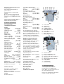
4.5 Machine description
Fig 1
A….Outfeed table
B….Jointer fence
C….ON/OFF switch
D….Cutterblock guard
E.....Table tilt handle
F….Table adjustment lock
G….Table adjustment handle
H….Infeed table
I…..Table-cabinet lock
J…..Mains plug (not Shown)
Fig 2
K….Thickness table
L….Power feed ON/OFF handle
M….Thickness table lock
N….Thickness table adjust handwheel
O.....Dust hood
P…..Dust hood disengagement knob
R.....Carry Handle
S.....E-Stop Switch
T..... E-Stop Switch
U.....Extension Table
5. Transport and start up
5.1 Transport and installation
For transport use a forklift or hand
trolley. Make sure the machine does not
tip or fall off during transport.
Remove the carriage blots and slide the
machine carefully off the pallet.

ATTENTION:
The planer tables are precisely aligned
ex. works. They may only be loaded
when they are closed and the table-
cabinet locks (I, Fig. 1) are engaged,
otherwise they may be damaged.
The purpose of 4 carry handles(R,
Fig. 2) is just to unload the machine
from the pallet when unpacking.
The machine is designed to operate in
closed rooms and must be placed
stable on firm and levelled ground.
The machine can be bolted down if
required.
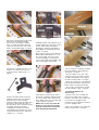
5.2 Assembly
If you notice any transport damage
while unpacking, notify your supplier
immediately. Do not operate the
machine!
Dispose of the packing in an
environmentally friendly manner.
Clean all rust protected surfaces with a
mild solvent.
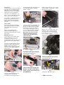
Mounting the Fence
To mount the fence assembly put to
hand the following: The fence tilt
assembly (E), fence (F), fence
mounting bracket with cap head screws
(G) and the two lift and shift handles
(H).
Line up the mounting bracket (G) pre-
drilled holes with the threaded holes
mid table to the rear of planer
thicknesser and secure using the two
cap head screws (B,Fig 3), With hex
key (A, Fig 3) .
Fig 3
Loosen the clamping handle on the
mounting bracket, insert the tilt
assembly base plate (E) through the
mounting bracket (G) sufficiently for the
next step. Lightly tighten clamping
handle, see Fig 4.
Fig 4
Locate the two lift and shift handles (H)
and the fence (F),see fig 19. Position
the fence up against the tilt assembly
housing (E). Line up the pre-drilled
holes in the mounting plate to the rear
fence assembly (F) with the elongated
slots in the tiltassembly housing (E).
Note: make sure the fence is the
right way up with themachined
cutout for the cutter block flush
against the tables.
Fig 5
Insert the thread of one of the lift and
shift handles (H) through the elongated
slot and screw it into the fence
mounting plate, see Fig 6.
Fig 6
(
Please note the lift and shift
handle has been removed to
make it easier to screw on the
threaded bolt.
)
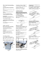
Replace the handle and secure in place
with the Phillips screw/spring, see Fig 7.
Repeat for the opposite.
Fig 7
Slide the fence (F) until it’s stop is up
against the tilt assembly housing (E)
then tighten the lift and shift handles.
Fence Stop (A), Fence stop clamping
Hex screw (B) see Fig 8.
Fig 8
Tilt fence assembly (A), Fence lift and
shift clamping handles (B), Scale (C),
Tilt clamping handle (D)
Fig 9
Tilt stop (A) ; Adjusting nut (B)
5.3 Mains connection

Mains connection and any extension
cords used must comply with applicable
regulations.
The mains voltage must comply with
the information on the machine licence
plate.
The mains connection must have a 16A
surge-proof fuse.
Only use connection cables marked
H07RN-F
Connections and repairs to the
electrical equipment may only be
carried out by qualified electricians.
ATTENTION:
-Check first if the cutter block runs
freely and if all safety devices are fitted
before starting the machine.
- If the direction of rotation is not
correct, the phase converter inside the
CCE Euro plug must be pushed in and
turned 180°.
(See rotation arrow on machine for
correct rotation)
5.4 Dust connection
Before initial operation, the machine
must be connected to a dust extractor.
The suction should switch on
automatically when the jointer is
switched on.
The flow rate on the suction port must
be 20m/sec.
Flexible hoses must be of non-
flammable quality, and must be
connected to the machine ground
system.
5.5 Starting operation
You can start the machine with the
green on button. The red button on the
main switch stops the machine. (C, Fig
10).
In case of emergency push the E-stop
button to stop the machine. (U, Fig 10).
Fig 10
The power feed can be engaged and
disengaged with handle (L, Fig 2).
In case of machine overload the motor
overload cut-off will react.
After appr.10 min of cooling the
machine can be started again.
6. Machine operation
Change of operating mode (planing
to thicknessing and back) may only
be performed when the machine is at
a complete standstill.
6.1 Jointing and planing
Correct operating position:
Position yourselves offset to the infeed
table (Fig 11).
Fig 11
Work piece handling:
Feed the work piece straight across the
infeed table, holding your fingers close
together, guiding the work piece with
the palm of your hands.
Never put your hands under the cutter
block cover.
Always keep your hands well clear of
the cutter block
Do not pull the work piece back over
the unguarded cutter block.
Always plane the work piece over its
entire length.
Adjust depth of cut with lever (G).
Loosen clamping knob (F) for
adjustment.
Fig 12
Support long work pieces (longer than
jointer tables) with helping roller stands
or table extensions.
Planing the face of a work piece up
to 75mm thick:
Place the work piece against the jointer
fence. Adjust the cutter block guard to
the height of the work piece. When
guiding the work piece, the hands slide
over the cutter block guard (Fig 13)
Fig 13
Planing the edge of a work piece
(jointing) or planning work pieces
more than 75mm thick:
Place the work piece against the jointer
fence.
Adapt the cutter block guard to the
width of the work piece (Fig 14).
Fig 14
Chamfering a work piece:
Place the work piece against the jointer
fence.
Adapt the cutter block guard to the
width of the work piece (Fig 15).
Fig 15

Planing of narrow work pieces:
Add an auxiliary fence to safely guide
narrow workpieces (see Fig 16).
Fig 16
Operating notes:
The planer tables are precisely aligned
ex. works. They may only be loaded
when the table-cabinet locks are
engaged, otherwise they may be
damaged or precision of machine be
lost.
Always use sharp cutter knives!
Check work piece for foreign objects
(nails, screws) and for loose knots.
Feed with thicker work piece end at the
front, hollow side downward.
Plane the stock with the grain, if
possible.
You get a better surface when planing
several passes with less chip removal.
Switch machine off if no further planing
is to be done immediately afterwards.
Cover the cutter block with the cutter
block guard.
Jointing and planing of short
workpieces may only be performed with
the help of tailor made push woods and
templates.
For the authorized use of the
machine observe the appendix A
“safe operation“
(on the last pages of this operating
manual)
A1: Planing, stock thickness below
75mm.
A2: Edge jointing.
A3: Planing of narrow gibs
A4: Planing of short stock with push
wood.
6.2 Thicknessing
Correct operating position:
To feed the work piece into the
machine, position yourselves offset to
one side of the feed opening.
Work piece handling
Adjust the planer table to the work
piece thickness.
Feed work piece slowly and straight into
the thicknesser. It will then be
automatically fed through the
thicknesser.
Guide work piece straight through the
thicknesser.
To remove the work piece from the
machine, position yourselves offset to
one side of the outfeed opening.
Support long work pieces with helping
roller stands.
Operating notes:
Always use sharp cutter knives!
Feed with thicker work piece end at the
front, hollow side downward.
Max. 4,5 mm depth of cut. If a work
piece gets stuck lower the planer table
by app. 1mm (1/4 crank turn).
Plane the stock with the grain, if
possible.
You get a better surface when planing
several passes with less chip removal.
Switch machine off if no further
planning is to be done immediately
afterwards.
Work pieces shorter than 150mm may
not be processed.
Machine max. 2 work pieces at one
time. Feed on both outer sides.
7. Setup and adjustments
General note:
Setup and adjustment work may only
be carried out after the machine is
protected against accidental starting.
Push the E-stop button
Pull the mains plug!
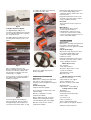
7.1 Changing cutterblock knives
The given instructions about knife
installation, maximum knife circle,
minimum knife clamping width and
correct knife lock blot tightening torque
must strictly be observed.
The cutter knives may only be changed
when the mains plug is pulled!
Risk of personal injury by cuts from the
cutter knives. Wear suitable gloves
when changing cutter knives.
Move cutter block cover to front and
fence to back.
Turn the four square-hear bolts of the
cutter knife lock bar all the way in (wear
gloves!).
At first remove cutter knife, then cutter
knife lock bar from the cutter block.
Clean all surfaces of cutter block and
cutter knife lock bar with a suitable
solvent (do not use cleaning agents that
could corrode the light metal
components).
Use only suitable cutter knives
conforming the technical specification
and EN 847-1
Unsuitable, incorrectly mounted, dull,
cracked of bent cutter knives can work
loose or increase the risk of kickback
considerably.
Always replace all three cutter knives at
once.
The cutter knife lock bars are balanced
to each other and thus can randomly be
placed.
Only cutter knives marked “HSS” or
“HS” can be resharpened!
When resharpening, remove the same
amount of material from all three cutter
knives, otherwise a balancing error may
cause damage to the bearings.
Cutter knives can only be resharpened
down to a minimum width of 15 mm.
Knives may not exceed the cutterblock
body by 1,1mm in radius.
Use genuine Jet replacement parts
only.
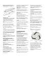
Changing the Standard Blades
Fig 17
Turn the cutter block until one of the
slots is in the upright position. Using a
4mm Hex key loosen the four cap head
screws on the cutter block, thus
removing the clamping effect. This
should allow the blade to ‘spring’ up,
protruding clear of the edge of the
cutter block, see Fig 18.
Carefully remove the blade and place
safely aside

Fig 18
Remove the blade holder and lay aside.
Clean the slot housing thoroughly,
remove any resin build-up, sawdust,
chips etc. Clean the blade holder and
ensure the circumference of the cutter
block is cleaned thoroughly, see Fig 19.
Fig 19
Remove the new blade from its keeper
and place the old blade in it’s place.
Locate the
blade setting tool (L), see
Fig 20.
Fig 20
Introduce the blade holder, position it
against the back of the slot, introduce
the blade in the front of the blade
holder. Carefully position the blade and
the holder to line up with the edge of
the cutter block. Press the blade setting
tool gently down onto the blade,
ensuring the locating feet are firmly
seated against the circumference of the
cutter blockand the blade is against the
setting recess, see Fig 21.
Fig 21
Holding the blade and setting tool (L) in
position, tighten two cap head screws to
provide a firm clamp on the blade.
Keeping the setting tool held firmly in
place tighten the remaining cap head
screws, see Fig 22.
Repeat the procedure for the other two
blades. When allthe blades are set at
the correct height, carry out a quick
check by rotating the cutter block in
reverse and visually inspectingthe edge
of the blade against a fixed point.
Fig 22
If this appears satisfactory, go round
and check everything is tight and lower
the surface tables and re-lock them in
place. Replace the fence assembly and
continue with the operation.
NOTE: You can also check that the
blades are set at thecorrect height
along the length of the cutter block
bythe following method below.
Fig 23
• Find a scrap piece of timber and draw
two measuring lines approximately 3-
4mm apart, see Fig 23.
• Place the timber to one side of the
cutter block across the tables and line
up right measuring line to the edge of
the outfeed surface table, see Fig 23.
• Rotate the cutter block so the blade tip
pulls the timber forward, stop when the
blade detaches itself from the timber.
• The rear line should now line up with
the outfeed table’s edge, see Fig 23.
7.2 Setting the Machine for
Thicknessing
1. Remove the fence assembly and
place it in its holder to the rear of the
machine. Unlock the surface table and
raise them to the upright position.
2. Rotate the dust extraction hood until
it’s in the upright position.
3. Raise the locking lever to engage the
thicknessing function, see Fig 24.

Fig 24
7.3 Digital Thickness Display
The ‘Digital Display’ will give an
accurate visual indication of the amount
you are adjusting the thicknessing table
in 0.10mm increments.
The digital display should be pre-set at
the fatory but if required can be set as
follows.
Fig 25
Place a straight edge across the
thicknessing table, raise the table until
the tip of the cutter-block blade at it’s
lowest pointis touching the top of the
straight edge, see Fig 25.
Using a vernier, measure the height of
the straight edge and write down the
reading, see Fig 26.
Fig 26
Loosen the grub screw holding the
collar mechanisum, turn the collar on
the digital display unit and dial in the
measurement you wrote down, see Fig
27. Tighten the grub screw, clamping
the collar to the drive shaft.
Fig 27
Remove the stright edge from the
thicknessing table.
8. Maintenance and inspection
General note:
Maintenance, cleaning and repair work
may only be carried out after the
machine is protected against accidental
starting.
Pull the mains plug!
Clean the machine regularly
Inspect the proper function of the dust
extraction daily.
Defective cutting knives must be
replaced immediately.
Before starting any work, check the
mobility of the anti-kickback fingers
(must fall down by their own weight).
Defective safety devices must be
replaced immediately.
All protective and safety devices must
be re-attached immediately after
completed cleaning, maintenance and
inspection work.
Repair and maintenance work on the
electrical system may only be carried
out by a qualified electrician.
Drive Belt:
The belt tension must be inspected
regularly.
Motor Break :
The motor break works electro-
mechanically (break motor).
If breaking time should exceed 10
seconds, the motor break assembly
needs to be replaced. Contact your Jet
service station immediately.
9. Trouble shooting
General note:
Maintenance, cleaning and repair work
may only be carried out after the
machine is protected against accidental
starting.
Pull the mains plug!
All protective and safety devices must
be re-attached immediately after
completed cleaning, repair and
maintenance work.
Repair and maintenance work on the
electrical system may only be carried
out by a qualified electrician.
Motor doesn’t start
*No electricity-
check mains and fuse.
*Defective switch, motor or cord-
consult an electrician.
*Overload has reacted-
Wait and restart.
Machine vibrates excessively
*Stand on uneven floor-
adjust stand for even support.
*Knives of different size-
all knives must have same width.
*Damaged knife-
replace knives set immediately
Cutting surfaces is bad
*Dull knives-
install sharp knives
*Cutter knives blocked by chips-
remove chips.
*Too heavy a cut-
make several passes.
*Knives cutting against grain-
plane work piece in opposite direction.
*Work piece inhomogeneous

*Moisture content too high
Snipe
*Inadequate support of long boards-
use helping roller stand.
*Dull knives-
sharpen knives.
*Knives set too high-
adjust the knives
set the outfeed table higher.
*Work piece twisted-
plane work piece before thicknessing.
Unparallel side to side
*Knife projection not uniform-
adjust knives with setting gauge.
Work piece jams
*Too much material removed in one
pass-
make several passes.
*Resin build-up on tables-
clean and wax table surfaces.
*Surface of feed rollers too smooth-
clean infeed roller with brush
roughen out feed roller with sandpaper.
Planer table difficult to adjust
*Lack of lubrication-
lubricate excenters and guides.
Thickness table difficult to adjust
*Lack of lubrication-
lubricate central post and screw.
*Thickness table lock is on-
loosen lock handle.
Poor machining power
*Main drive belt slipping-
tighten or replace belt.
*Resin build-up on tables-
clean and wax table surfaces.
*Dull knives-
install sharp knives.
10. Environmental protection
Protect the environment.
Your appliance contains valuable
materials which can be recovered or
recycled. Please leave it at a
specialized institution.
This symbol indicates separate
collection for electrical and electronic
equipment required under the WEEE
Directive (Directive 2012/19/EC) and is
effective only within the European
Union.
11. Available accessories
Stock number 10000287
Set of 3 high speed steel (HSS) knives
260 x 25 x 3mm (JPTF260-C33)
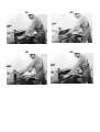
12. Safe operation
See appendix A (on the last pages of
this operating manual)
A1: Planing, stock thickness below
75mm
A2: Edge jointing
A3: Planing of narrow gibs
A4: Planing of short stock with push
wood.

A1
A2
A3
A4
-
 1
1
-
 2
2
-
 3
3
-
 4
4
-
 5
5
-
 6
6
-
 7
7
-
 8
8
-
 9
9
-
 10
10
-
 11
11
-
 12
12
-
 13
13


in anderen Sprachen
- English: JET JPT-F260-M User manual
Verwandte Artikel
Andere Dokumente
-
 Elektra Beckum HC 260 Operating Instructions Manual
-
Metabo HC 410 Benutzerhandbuch
-
Scheppach Bestcombi 5.0 Benutzerhandbuch
-
Scheppach 1902207901 Benutzerhandbuch
-
-
DeWalt DW733S Bedienungsanleitung
-
Metabo HC 260 C 2,80 DNB Bedienungsanleitung
-
-
Scheppach HMS850 Benutzerhandbuch
