CombiSteel 7227.0010 Benutzerhandbuch
- Kategorie
- Dunstabzugshauben
- Typ
- Benutzerhandbuch

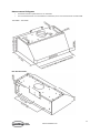
Under cabinet range hood
7227.0005 - 7227.0010
User Manual
Gebruikershandleiding
Gebrauchsanweisung
Le mode d’emploi

2
www.combisteel.com
CONTENT
ENGLISH
Important Safety Notice ......................................................................................................................................... 4
INSTALLATION ......................................................................................................................................................... 6
Tools needed ....................................................................................................................................................... 6
Parts supplied ..................................................................................................................................................... 6
Venting requirements ......................................................................................................................................... 7
Mount heights & clearance ................................................................................................................................ 8
Calculating vent system length ........................................................................................................................... 9
Venting methods ................................................................................................................................................. 9
Electrical requirements ..................................................................................................................................... 10
Preparation ....................................................................................................................................................... 11
Installation ........................................................................................................................................................ 12
Range hood operations ..................................................................................................................................... 14
USE AND CARE ...................................................................................................................................................... 15
Troubleshooting ................................................................................................................................................ 15
Use and care information ................................................................................................................................. 16
Specifications .................................................................................................................................................... 16
Measurements & diagrams............................................................................................................................... 17
MAINTENANCE ..................................................................................................................................................... 21
WARRANTY ........................................................................................................................................................... 23
Disclaimer ......................................................................................................................................................... 24
Contact us ......................................................................................................................................................... 24
NEDERLANDS
Belangrijke veiligheidsinformatie ......................................................................................................................... 25
INSTALLATIE .......................................................................................................................................................... 27
Benodigd gereedschap ..................................................................................................................................... 27
Meegeleverde onderdelen ............................................................................................................................... 27
Ventilatievereisten ............................................................................................................................................ 28
Montagehoogten en speling ............................................................................................................................. 29
Berekenen van de lengte van het ventilatiesysteem ........................................................................................ 30
Ventilatiemethoden .......................................................................................................................................... 30
Elektrische voorschriften .................................................................................................................................. 31
Voorbereiding ................................................................................................................................................... 32
Installatie .......................................................................................................................................................... 33
Afzuigkapbedieningen ...................................................................................................................................... 35
GEBRUIK EN ONDERHOUD ................................................................................................................................... 36
Problemen oplossen ......................................................................................................................................... 36
Gebruiks en onderhoudsinformatie .................................................................................................................. 37
Specificaties ...................................................................................................................................................... 37
Afmetingen & diagrammen .............................................................................................................................. 38
ONDERHOUD ........................................................................................................................................................ 42
GARANTIE ............................................................................................................................................................. 44
Disclaimer ......................................................................................................................................................... 45
Contact met ons opnemen ............................................................................................................................... 45

3
www.combisteel.com
DEUTSCH
Wichtiger Sicherheitshinweis ............................................................................................................................... 46
INSTALLATION ....................................................................................................................................................... 48
Benötigte Werkzeuge ........................................................................................................................................ 48
Gelieferte Teile .................................................................................................................................................. 48
Abzugsanforderungen ....................................................................................................................................... 49
Montagehöhen & Freiraum .............................................................................................................................. 50
Berechnung der Länge des Lüftungssystems .................................................................................................... 51
Lüftungsmethoden ........................................................................................................................................... 51
Elektrische Anforderungen ............................................................................................................................... 52
Vorbereitung ..................................................................................................................................................... 53
Installation ........................................................................................................................................................ 54
Bedienung der Dunstabzugshaube ................................................................................................................... 56
GEBRAUCH UND PFLEGE ....................................................................................................................................... 57
Fehlerbehebung ................................................................................................................................................ 57
Gebrauchs- und Pflegehinweise ....................................................................................................................... 58
Technische Daten .............................................................................................................................................. 58
Abmessungen & Diagramme ............................................................................................................................ 59
WARTUNG ............................................................................................................................................................. 63
GARANTIE ............................................................................................................................................................. 65
Haftungsausschluss ........................................................................................................................................... 66
Kontaktieren Sie uns ......................................................................................................................................... 66
FRANÇAIS
Avis de sécurité important .................................................................................................................................... 67
INSTALLATION ....................................................................................................................................................... 69
Outils nécessaires ............................................................................................................................................. 69
Pièces fournies .................................................................................................................................................. 69
Exigences de ventilation ................................................................................................................................... 70
Hauteurs de montage et dégagement .............................................................................................................. 71
Calcul de la longueur du système d'évacuation ................................................................................................ 72
Méthodes de ventilation .................................................................................................................................. 72
Exigences électriques ........................................................................................................................................ 73
Préparation ....................................................................................................................................................... 74
Installation ........................................................................................................................................................ 75
Opérations de la hotte ...................................................................................................................................... 77
UTILISATION ET ENTRETIEN .................................................................................................................................. 78
Dépannage ........................................................................................................................................................ 78
Informations d'utilisation et d'entretien........................................................................................................... 79
Caractéristiques ................................................................................................................................................ 79
Mesures et diagrammes ................................................................................................................................... 80
MAINTENANCE ..................................................................................................................................................... 84
GARANTIE ............................................................................................................................................................. 86
Avertissement ................................................................................................................................................... 87
Contactez-nous ................................................................................................................................................. 87

4
www.combisteel.com
Important Safety Notice
Read all Instructions before Installing and operating this appliance
• The installation in this manual is intended for qualified installers, service technicians or persons with
similar qualified background. Installation and electrical wiring must be done by qualified professionals
and in accordance with all applicable codes and standards, including fire-rated construction.
• DO NOT attempt to install this appliance yourself. Injury could result from installing the unit due to lack
of appropriate electrical and technical background.
• Range hood may have very sharp edges; please wear protective gloves if it is necessary to remove any
parts for installing, cleaning or servicing.
• Activating any switch ON before completing installation may cause ignition or an explosion.
• Due to the size and weight of this range hood, two people installation is recommended.
To reduce the risk of fire, electric shock, or injury to persons:
• For general ventilating use only. DO NOT use to exhaust hazardous or explosive materials and vapors.
• The combustion air flow needed for safe operation of fuel-burning equipment may be affected by this
unit’s operation. Follow the heating equipment manufacturer’s guideline and safety standards such as
those published by the National Fire Protection Association (NFPA), and the American Society of Heating,
Refrigeration and Air Conditioning Engineers (ASHRAE), and the local code authorities.
• Before servicing or cleaning unit, switch power OFF at service panel and lock service panel to prevent
power from being switched ON accidentally.
• Clean grease laden surfaces frequently. To reduce the risk of fire and to disperse air properly, make sure
to vent air outside. DO NOT vent exhaust into spaces between walls, crawl spaces, ceiling, attics or
garages.
• Ducted fans MUST always be vented to the outdoors.
• Use only metal ductwork and this unit MUST be grounded.
• Sufficient air is needed for proper combustion and exhausting of gases through the duct to prevent back
drafting.
• When cutting or drilling into wall or ceiling, be careful not to damage electrical wiring or other hidden
utilities.
• All electrical wiring must be properly installed, insulated and grounded.
• Old duct work should be cleaned or replaced if necessary to avoid the possibility of a grease fire.
• Check all joints on duct work to insure proper connection and all joints should be properly taped.
• Use this unit only in the manner intended by the manufacturer. If you have questions, contact the vendor.
To reduce the risk of a stove top grease fire:
• Keep all fan, baffle, spaces, filter, grease tunnel, oil container and grease-laden surfaces clean. Grease
should not be allowed to accumulate on fan, baffle, spaces, filter, grease tunnel and oil container.
• Always turn range hood ON when cooking at high heat or when cooking flaming foods.
• Use high settings on cooking range only when necessary.
• Never leave surface units unattended at high settings. Boil overs cause smoking and greasy spillovers
that may ignite. Heat oils slowly on low or medium settings.
• Clean ventilating fan frequently.
• Always use appropriate cookware and utensils size.
• Always use cookware appropriate for the size of the surface element.

5
www.combisteel.com
To reduce the risk of injury to persons in the event of a stove top grease fire:
• SMOTHER FLAMES with a close-fitting lid, cookie sheet, or metal tray, then turn OFF the burner.
BECAREFUL TO PREVENT BURNS. NEVER PICK UP A FLAMING PAN—you may be burned. KEEP
FLAMMABLE OR COMBUSTIBLE MATERIAL AWAY FROM FLAMES. If the flames DO NOT go out
immediately, EVACUATE AND CALL THE FIRE DEPARTMENT or dial your local emergency service
immediately.
• DO NOT USE WATER, including wet dishcloths or towels — a violent steam explosion will result.
• Use an extinguisher ONLY if:
• You know you have a Class A, B, C extinguisher, and you already know how to operate it.
• The fire is small and contained in the area where it is started.
• The fire department is being called.
• You can fight the fire with your back to an exit.
To reduce the risk of injury to persons in the event of a gas leaks:
• Extinguish any open flame.
• DO NOT turn on the range hood fan or any type of ventilator.
• DO NOT turn on the lights or any type of appliance.
• Open all doors and windows to disperse the gas. If you still smell gas, call the gas company and fire
department, or dial your local emergency service immediately.
Your safety and the safety of others is very important. We have provided many important safety messages in this
manual and on your appliance. Always read and obey all safety messages. All safety messages will tell you what
the potential hazard is, tell you how to reduce the chance of injury, and tell you what can happen if the
instructions are not followed.
WARNING
This is the safety alert symbol. This symbol alerts you to potential hazards that can hurt you and others. All safety
messages will follow the safety alert symbol and the word “WARNING”.
The manufacturer and/or distributor/reseller declines all responsibility in the event of failure to observe the
instructions given here for installation, maintenance and suitable use of the product. The manufacturer and/or
distributor/reseller further declines all responsibility for injury due to negligence and the warranty of the unit
automatically expires due to improper maintenance.
The manufacturer and/or distributor/reseller will not be held responsible for any damages to personal
property or real estate or any bodily injuries whether caused directly or indirectly by the range hood.

6
www.combisteel.com
INSTALLATION
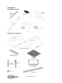
Tools needed
Parts supplied

7
www.combisteel.com
Venting requirements
• Vent system must terminate to the outside (roof or side wall).
• DO NOT terminate the vent system in an attic or other enclosed area.
• DO NOT use 4” (10.2 cm) laundry-type wall caps.
• Use metal/aluminum vent only. Rigid metal/ aluminum vent is recommended.
• DO NOT use plastic vent.
• Always keep the duct clean to ensure proper airflow.
• Calculate the following figures before installation:
1. Distance from the floor to the ceiling.
2. Distance between the floor to the countertop/stove (recommend* 27” to 30”).
3. Distance between the countertop/stove to the range hood.
4. Height of hood and duct cover.
For the most efficient & quiet operation:
• A distance of 27” to 30” is recommended* between stove top and the bottom of range hood.
• It is recommended that the range hood be vented vertically through the roof through 8” (20.3 cm) or
bigger round metal/aluminum vent work.
• The size of the vent should be uniform.
• Use no more than three 90° elbows.
• Make sure there is a minimum of 24” (61 cm) of straight vent between the elbows if more than one
elbow is used.
• DO NOT install two elbows together.
• The length of vent system and number of elbows should be kept to a minimum to provide efficient
performance.
• The vent system must have a damper. If roof or wall cap has a damper, DO NOT use damper (if supplied)
on top of the range hood.
• Use silver tape or duct tape to seal all joints in the vent system.
• Use caulking to seal exterior wall or roof opening around the cap.
* Due to different ceiling height configurations, recommended height may not be applicable.

8
www.combisteel.com
Mount heights & clearance
IMPORTANT:
• A minimum of 8” round (standard for this
range hood) or 3-1/4 x 10” rectangular duct
(purchased separately) must be used to
maintain maximum airflow efficiency.
• Always use rigid type metal/aluminum
ducts if available to maximize airflow when
connecting to provided duct.
• Please use Duct Run Calculation below to
compute total available duct run when
using elbows, transitions and caps.
• ALWAYS, when possible, reduce the
number or transitions and turns. If long
duct run is required, increase duct size from
8” to 10”. If a reducer is used, install a long
reducer instead of a pancake reducer.
Reducing duct size will restrict airflow and
decrease airflow, thus reduce duct size as
far away from opening as possible.
• If turns or transitions are required: Install as
far away from opening and as far apart,
between 2, as possible.
• Minimum mount height between stove top
to hood bottom should be no less than 27-
inch*.
• Maximum mount height between stove top
to hood bottom should be no higher than
30-inch*.
• It is important to install the hood at the
proper mounting height. Hoods mounted
too low could result in heat damage and
fire hazard; while hoods mounted too high
will be hard to reach and will lose its
performance and efficiency.
• If available, also refer to stove top
manufacturer’s height clearance
requirements and recommended hood
mounting height above range.
* Due to different ceiling height configurations,
recommended height may not be applicable.
Minimum Duct Size:
• Round - 8” minimum
• Rectangular - 3-1/4 x 10” minimum
(requires a 8” to 3-1/4x10” adaptor, not
supplied)

9
www.combisteel.com
Calculating vent system length
To calculate the length of the system you need, deduct the equivalent feet for each vent piece used in the system
from the recommended maximum duct run.
Duct Run Calculation
Recommended maximum run
8” or 3-1/4 x 10” duct
50 ft
Vent piece deduction
Each 90º elbow used
9 ft
Each 45º elbow used
5 ft
Each 7” to 3/14 x 10” transition used
7 ft
Side wall cap with damper
0 ft
Roof cap
0 ft
Duct Run Calculation example:
One roof cap, two 90º elbow, and one 45º elbow used:
0ft + 9ft + 9ft + 5ft = 23ft used.
Deduct 23ft from 50ft, 27ft maximum available for straight duct run.
Venting methods
• This range hood is factory set for venting
through the roof or wall.
• Vent work can terminate either through
the roof or wall. To vent through a wall, a
90° elbow is needed.
IMPORTANT:
• NEVER exhaust air or terminate duct
work into spaces between walls, crawl
spaces, ceiling, attics or garages.
All exhaust must be ducted to the
outside.
• Use metal/aluminum duct work only.
• Fasten all connections with sheet metal
screws and tape all joints with certified
Silver Tape or Duct Tape.
• Use caulking to seal exterior wall or roof
opening around the cap.

10
www.combisteel.com
Electrical requirements
IMPORTANT: Observe all governing codes and ordinances.
(Please consult with a qualified electrician for 220-Volt 50 Hz voltage)
It is the customer’s responsibility:
• To contact a qualified electrical installer.
• To assure that the electrical installation is adequate and in conformance with National Electrical Code,
ANSI/NFPA 70 — latest edition*, or CSA Standards C22. 1-94, Canadian Electrical Code, Part 1 and C22.
2 No. 0-M91 - latest edition** and all local codes and ordinances.
If codes permit and a separate ground wire is used, it is recommended that a qualified electrician determine that
the ground path is adequate.
A 120-Volt, 60 Hz, AC-only, fused electrical supply is required on a separate 15-amp circuit, fused on both sides
of the line.
DO NOT ground to a gas pipe.
Check with a qualified electrician if you are not sure that the range hood is properly grounded.
DO NOT have a fuse in the neutral or ground circuit.
IMPORTANT: Save this Installation Guide for electrical inspector’s use.
The range hood must be connected with copper wire/plug only.
The range hood should be connected directly to the fused disconnect (or circuit breaker) box through flexible
armored or non-metallic sheathed copper cable. A U.L. - or C.S.A. - listed strain relief must be provided at each
end of the power supply cable.
Wire sizes (copper wire only) and connections must conform with the rating of the appliance as specified on
the model/serial rating label. Wire sizes must conform to the requirements of the National Electrical Code
ANSI/NFPA 70 — latest edition*, or CSA Standards C22. 1-94, Canadian Electrical Code Part 1 and C22.
2 No. 0-M91 - latest edition** and all local codes and ordinances. A U.L. - or C.S.A. - listed conduit connector
must be provided at each end of the power supply cable (at the range hood and at the junction box).
Copies of the standards listed may be obtained from:
* National Fire Protection Association
Batterymarch Park
Quincy, Massachusetts 02269
** CSA International
8501 East Pleasant Valley Road
Cleveland, Ohio 44131-5575

11
www.combisteel.com
Preparation
Advanced Preparations:
• Be familiar with the controls of the range hood by
reading through Range Hood Operations, Page 14.
• Place the range hood on a flat, stable surface. Connect
the range hood to a designated standard outlet
(please refer the product label for the suitable voltage
of this unit) and turn on the range hood. Verify all
operations of the range hood by referring to Range
Hood Operations, Page 14.
• Place all supplied parts and required hardware on a
flat, stable surface and verify the existence of all
supplied parts listed on Page 6.
• Carefully remove the white plastic protective coat
from the range hood.
Preparations:
NOTE: To avoid damage to your hood, prevent debris from entering the vent opening.
• Decide the location of the venting pipe from the hood to the outside. Refer to Venting Methods on
Page 9.
• A straight, short vent run will allow the hood to perform more efficiently.
• Try to avoid as many transitions, elbows, and long run as possible. This may reduce the performance of
the hood.
• IMPORTANT: Peel white plastic protective coat off the hood, if any.
• Use silver tape or duct tape to seal joints between pipe sections.
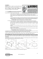
• For installing under the cabinet with recessed bottom, attach 4-inch wide wood filler strips (not
provided) on each side. Refer to Figure 1.
• Using references in Measurements and Diagrams on Page 17, create access opening for electrical wires
and hood exhaust under the cabinet.
CAUTION: If moving the cooking range is necessary to install the hood, turn OFF the power on an electric range
at the main electrical box. SHUT OFF THE GAS BEFORE MOVING A GAS RANGE.
• Puncture the knockout holes (for mounting under the cabinet) on the hood as shown in Figure 2.
• If necessary, attach two rubber stands with 3M adhesive tapes to the back corners of the hood.

12
www.combisteel.com
Installation
Installations (refer to Page 4 for parts): Measure the
distance between stove top and the bottom of range
hood. A distance of 27” to 30” is recommended*.
*Due to different ceiling height configurations,
recommended height may not be applicable.
1. You have two ways (A or B) to mount this range hood:
A. Proceed if you would like to mount this range
hood without using the hood-mounting bracket.
1. Using references in Height & Clearance on Page 8 and Mea Measurements and Diagrams on
Page 17, center the hood beneath the cabinet and flush with the front of the cabinet.
2. Draw electrical wires through cabinet access opening and center the hood beneath the
cabinet.
3. From inside of the hood, place screws into the exact center of each knockout hole and secure
to cabinet bottom. Finish tightening all screws until secure. Be careful when using electrical
screwdriver, damage to the range hood may occur. Skip Part B below and proceed to Step 2.
CAUTION: Make certain the range hood is secure before releasing!
B. Proceed if you would like to mount this range hood using the provided hood-mounting bracket.
1. Using references in Height & Clearance on Page 8 and Measurements and Diagrams on
Page 17, mark the leveling point of the hood. Position two mounting screws on the wall, leaving
1/8” space away from the wall. Mounting the hood on wall studs or lumbers is highly
recommended.
2. Attach the hood-mounting bracket to the back of the hood with six screws as shown in
Figure 3.
3. Puncture the knockout wire access hole at the back of the hood and draw the electrical wires
through as shown in Figure 4.
4. Align hood-mounting bracket to the screws on the wall and hook hood into place as shown
in Figure 5. Tighten screws to secure hood to the wall.
CAUTION: Make certain the range hood is secure before releasing!
2. For safety purpose, pre-drilled mounting holes are provided through the back of the hood. For a more secure
installation, use as many mounting holes as needed to secure from the inside of hood.
3. Use 8” round steel pipe (follow building codes in your area) to connect the exhaust on the hood to the
ductwork above. Use silver tape or duct tape to make all joints secure and air tight. Refer to Figure 6.
SAFETY WARNING: Risk of electrical shock. this range hood must be properly grounded. Make sure this is done
by qualified electrician in accordance with all applicable national and local electrical codes. Before connecting
wires, switch power off at service panel and lock service panel to prevent power from being switched on
accidentally.
4. Connect the range hood to a designated standard outlet or cut off the plug and connect three wires (black,
white and green) to house wires and cap with wire connectors.
5. Store excess wires in the wiring box.
6. Drop oil tunnel into recess support near rear of hood. Refer to Figure 8.

13
www.combisteel.com
7. To install baffle filters and stainless spacer(s), refer to figure 9 for the following five steps:
1. Angle baffle filter toward back of hood.
2. Push baffle filter up until almost level.
3. Slide forward into recess behind the front of hood.
4. Lower baffle filter.
5. Slide back until it fits into resting positions.
8. Repeat Step 7 to install all baffle filters and stainless spacers.
9. Turn power ON in control panel. Check all lights and fan operations.
10. Make sure to leave this Installation Guide for the homeowner.

14
www.combisteel.com
Range hood operations
Control Panel Layout and Buttons Configurations:
This range hood is equipped with a heat sensor that will self-calibrate in 5 seconds when the range hood is first
electrically activated and beeps when self-calibration is done. To conserve energy, the LCD panel will turn off
automatically after 5 seconds of inactivity.
Adjusting Heat Sensitive Auto Speed (HSAS) Function:
• Press Auto Function button to Turn On/Off the Auto Mode. The Auto Function Icon will appear in the
LCD Panel when Auto Mode is On.
• While the range hood is off, press and hold Auto Function button to enter the temperature setting mode.
Press Increase or Decrease button to adjust the comparison temperature value between the internal
and external heat sensors from 7°F to 20°F. The temperature setting mode will exit automatically after
5 seconds of inactivity.
• While the range hood is off and Auto Function is activated, the blower will turn on to its highest speed
automatically when the internal temperature is 4 times above the external temperature. Then it will
adjust the speed level (between speed levels F4 to F1) automatically according to the detected
temperature between the sensors (4 times to 1 time). The speed level can also be manually overwritten
by press the Increase or Decrease button and Auto Function will reactivate after 2 minutes. The blower
can ONLY be turned off MANUALLY or activate the delay off timer function.
Activating Normal Blower Function:
• While the range hood is off, press Increase or Decrease button to start the blower. Press Increase button
to increase blower speed (F1 to F4) as indicated in LCD panel. The Increase button cycles blower settings
from off (00), quiet speed (F1), low speed (F2), medium speed (F3) to high speed (F4).
• While the range hood is on and the blower is running, press Decrease button to decrease blower speed
(F4 to F1) as indicated in LCD panel. The Decrease button cycle blower settings from high speed (F4), to
medium speed (F3), low speed (F2), quiet speed (F1) to off (00).
Activating Light Function:
• Press Light button once to turn on the lights, and once again to turn off the lights.
CAUTION: DO NOT touch the lights until switched OFF and cooled.
Activating Power-Off Delay Function:
• While the range hood is on and the blower is running, press Power-Off Delay button to activate delay
off timer and “Power-Off Delay” icon will appear in LCD panel. Adjust to desired period of delay off
timer by pressing Increase or Decrease button (minimum 1 minute to maximum 15 minutes). Timer
begins to countdown immediately, when it reaches 0, the blower will shut off.
Adjusting Clock Function:
• While the range hood is off, press Power-off Delay button once to enter the clock setting mode, press
Increase or Decrease button to set the Hour. Press the Power-off Delay button again to set the Min.
Press the Power-off Delay button again to exit the clock setting mode.
Note: Light settings are independent from other settings (including power-off delay) and lights have to be
manually turned on or off.

15
www.combisteel.com
USE AND CARE
Troubleshooting
If the range hood or halogen light does not
operate after installation:
• Check if the range hood has been plugged in, make
sure that all power has been turned back ON, fused
not blown and all electrical wiring are properly
connected.
• Swap out light assembly to working ones to
determine whether it is caused by defective bulbs.
See Replacing the light bulbs on Page 21/22.
The range hood vibrates when the blower is on:
• The range hood might not have
The blower or fan seems weak:
• Check that the duct sized used is at least 8” or 3-1/4
x 10”. Range hood WILL NOT function efficiently with
insufficient duct size. For example: 10” duct over 8”
hole and loosely secured.
• Check if duct is clogged or if damper unit (half-
circular flapper) is not installed correctly or opening
properly. A tight mesh on a side wall cap unit might
also cause restriction to the air flow.
The lights work but the blower is not spinning
at all, is stuck or is rattling.
• The blower might be jammed or scraping the bottom
• due to shipping damage. Please contact us
immediately.
The hood is not venting out properly:
• Make sure the distance between the stove top and
the bottom of the hood is within* 27” and 30” in
distance. *Due to different ceiling height
configurations, recommended height may not be
applicable.
• Reduce the number of elbows and length of duct
work. Check if all joints are properly connected,
sealed, and taped.
• Make sure the power is on high speed for heavy
cooking.

16
www.combisteel.com
Use and care information
Operations:
• Read and understand all instructions and warnings in this manual before operating the appliance. Save
these instructions for future reference.
• Always leave safety grills and filters in place. Without these components, operating blowers could catch
on to hair, fingers and loose clothing.
• NEVER dispose cigarette ashes, ignitable substances, or any foreign objects into blowers.
• NEVER leave cooking unattended. When frying, oil in the pan can easily overheat and catch fire. The risk
of self-combustion is higher when the oil has been used several times.
• NEVER cook on “open” flames under the range hood. Check deep-fryers during use: Superheated oil
may be flammable.
Cleaning:
• The saturation of greasy residue in the blower and filters may cause increased inflammability. Keep unit
clean and free of grease and residue build-up at all times to prevent possible fires.
• Filters must be cleaned periodically and free from accumulation of cooking residue (see cleaning
instructions on Page 21). Old and worn filters must be replaced immediately.
• DO NOT operate blowers when filters are removed. Never disassemble parts to clean without proper
instructions. Disassembly is recommended to be performed by qualified personnel only. Read and
understand all instructions and warnings in this manual before proceeding.
Specifications
Specifications3:
Body Design
Seamless Stainless Steel, Satin Finish
Power Rating
220V/50Hz
General Input Power
240W + (# of Light x Wattage)
Motor Input Power
240W (120W + 120W)
Ampere
3A
Levels Of Speed Control
4 Levels
Airflow1 (Q/L/M/H)
385CFM / 490CFM / 615CFM / 900CFM
Noise Level23 (Q/L/M/H)
1.5Sone(46dB) / 3.5Sone(58dB) / 5.3Sone(64dB) / 7.5Sone(69dB)
Number Of Motors
2 Motors
Motor Type
Single Chamber Ultra Quiet
Fan Type
Centrifugal Squirrel Cage
Control Type
Touch Sensitive Electronic Control Panel w/ Heat Sensor
Filtration Type
Stainless Steel Baffle Filter
Illumination
LED 3W 12V
Venting Size
Top, 8 inches Round
Interference Protection
Radio Frequency Interference Protected
1
. In House Test Static Pressure “0”.
2
. One sone is roughly equivalent to the sound of a refrigerator (1kHz) at 40 decibels.
3
. Subject to change without notice, please contact your local reseller for details.

17
www.combisteel.com
Measurements & diagrams
• All measurements in parenthesis are in millimeter.
• All inch measurements are converted from millimeters, thus inch measurements are estimated.
7227.0005 – 7227.0010
Rear Knockout Holes:

18
www.combisteel.com
Hood-mounting Bracket:
Circuit Diagram:

19
www.combisteel.com
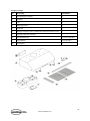
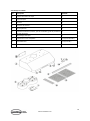
Range Hood Assembly:
No.
Description
Quantity
1
Hood-Mounting Bracket
1
2
Hood Body
1
3
Light
2
4
Control Panel
1
5
Oil Tunnel
1
6
Blower Assembly (Motor, Fan Blade, Protective Grill and Squirrel Cage)
1
7
Electrical Assembly
1
8
Stainless Steel Spacer
1 / (2 for 42 & 48”)
9
Baffle Filter
2 / (3 for 48”)
10
Power Cord
1

20
www.combisteel.com
Blower Assembly:
No.
Description
No.
Description
1
Spuirrel Cage
8
Right Fan Blade
2
Screw Cap
9
Gasket
3
Left Fan Blade
10
Screws (3/16” x 3/8”)
4
Left Locknut
11
Left Motor
5
Air Flow Grill
12
Right Motor
6
Screws (3/16” x 3/8”)
13
Protective Grill
7
Right Locknut
Seite laden ...
Seite laden ...
Seite laden ...
Seite laden ...
Seite laden ...
Seite laden ...
Seite laden ...
Seite laden ...
Seite laden ...
Seite laden ...
Seite laden ...
Seite laden ...
Seite laden ...
Seite laden ...
Seite laden ...
Seite laden ...
Seite laden ...
Seite laden ...
Seite laden ...
Seite laden ...
Seite laden ...
Seite laden ...
Seite laden ...
Seite laden ...
Seite laden ...
Seite laden ...
Seite laden ...
Seite laden ...
Seite laden ...
Seite laden ...
Seite laden ...
Seite laden ...
Seite laden ...
Seite laden ...
Seite laden ...
Seite laden ...
Seite laden ...
Seite laden ...
Seite laden ...
Seite laden ...
Seite laden ...
Seite laden ...
Seite laden ...
Seite laden ...
Seite laden ...
Seite laden ...
Seite laden ...
Seite laden ...
Seite laden ...
Seite laden ...
Seite laden ...
Seite laden ...
Seite laden ...
Seite laden ...
Seite laden ...
Seite laden ...
Seite laden ...
Seite laden ...
Seite laden ...
Seite laden ...
Seite laden ...
Seite laden ...
Seite laden ...
Seite laden ...
Seite laden ...
Seite laden ...
Seite laden ...
-
 1
1
-
 2
2
-
 3
3
-
 4
4
-
 5
5
-
 6
6
-
 7
7
-
 8
8
-
 9
9
-
 10
10
-
 11
11
-
 12
12
-
 13
13
-
 14
14
-
 15
15
-
 16
16
-
 17
17
-
 18
18
-
 19
19
-
 20
20
-
 21
21
-
 22
22
-
 23
23
-
 24
24
-
 25
25
-
 26
26
-
 27
27
-
 28
28
-
 29
29
-
 30
30
-
 31
31
-
 32
32
-
 33
33
-
 34
34
-
 35
35
-
 36
36
-
 37
37
-
 38
38
-
 39
39
-
 40
40
-
 41
41
-
 42
42
-
 43
43
-
 44
44
-
 45
45
-
 46
46
-
 47
47
-
 48
48
-
 49
49
-
 50
50
-
 51
51
-
 52
52
-
 53
53
-
 54
54
-
 55
55
-
 56
56
-
 57
57
-
 58
58
-
 59
59
-
 60
60
-
 61
61
-
 62
62
-
 63
63
-
 64
64
-
 65
65
-
 66
66
-
 67
67
-
 68
68
-
 69
69
-
 70
70
-
 71
71
-
 72
72
-
 73
73
-
 74
74
-
 75
75
-
 76
76
-
 77
77
-
 78
78
-
 79
79
-
 80
80
-
 81
81
-
 82
82
-
 83
83
-
 84
84
-
 85
85
-
 86
86
-
 87
87


CombiSteel 7227.0010 Benutzerhandbuch
- Kategorie
- Dunstabzugshauben
- Typ
- Benutzerhandbuch
in anderen Sprachen
- English: CombiSteel 7227.0010 User manual
- français: CombiSteel 7227.0010 Manuel utilisateur
- Nederlands: CombiSteel 7227.0010 Handleiding