Profi-pumpe INVERTER Pumpensteuerung IPC2 Bedienungsanleitung
- Typ
- Bedienungsanleitung

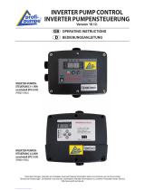
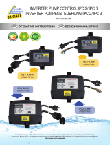
INVERTER PUMP CONTROL
INVERTER PUMPENSTEUERUNG
Version 20.12.
OPERATING INSTRUCTIONS
BEDIENUNGSANLEITUNG
de
Technical changes, misprints and mistakes reserved! Newest information about our products can be found online
Technische Änderungen, Druckfehler und Irrtümer vorbehalten! Aktuelle Informationen zu unseren Produkten nden Sie auf:
http://www.pro-pumpe.de
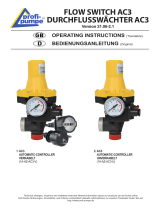
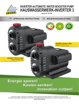
INVERTER-PUMPEN-
STEUERUNG 2-1,1KW
(IPC-2)
(PSM01134U)
INVERTER-PUMPEN-
STEUERUNG 3-2,2KW
(IPC-3)
(PSM01135U)

Contents
1. Introduction ......................................................................................................................... 2
2. In general ............................................................................................................................ 2
3. Installation ........................................................................................................................... 3
4. Wiring .................................................................................................................................. 3
5. Operation ............................................................................................................................. 4
6. Security tips ......................................................................................................................... 5
7. Servicing ............................................................................................................................. 7
8. Maintenance ....................................................................................................................... 8
9. Guarantee regulations ........................................................................................................ 8
10. Recognising and repairing of mistakes ............................................................................... 8
11. Notes on Product Liability .................................................................................................. 8
12. Notes on Disposal .............................................................................................................. 9
13. EU Declaration of Conformity ............................................................................................ 9
14. Technical Data ................................................................................................................. 20
2 English
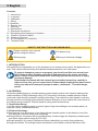
SAFETY INSTRUCTION AND WARNINGS
Please read the user manual
before using the device Pull power plug
Warning sign Warning of electrical voltage
1. INTRODUCTION
We would like to congratulate you on the purchase of our Inverter pump control. We appreciate your
trust. That‘s why funtional security and operational safety stands by us on rst place.
To prevent damage to persons or property, you should read this user manual care-
fully. Please observe all safety precautions and instructions for proper use of the
device. Failure to follow the instructions and safety precautions can result in injury
or property damage.
Please keep this manual with the instructions and safety instructions carefully in
order to at any time you can restore them. Please always download the latest version
of the user manual of www.pro-pumpe.de under „downloads“. This shall always
prevail.
2. IN GENERAL
AD series variable frequency constant pressure water supply system is the industry leading pulse
width modulation (PWM) technology using VVVF frequency conversion variable pressure control
mode and combined with a pressure sensing technology. It can adjust the motor speed in real time
through real-time monitoring of pipe network pressure changes, so as to realize the control mode of
the outlet pressure constant. This also leads to saving water and electricity.
2.1 Application Range
It can be used for supplying water to various types of high-rise buildings such as water plants, re-
staurants, hotels, residential areas etc.
2.2 Product Advantage
l To master the core technology: It has three national invention patent. It also has the core of the
PID algorithm to control motor drive technology.
l Energy-ecient: Compared with the traditional way of water supply, the frequency constant pres-
sure water supply saves energy by 30%-60%.
l Simple operation: It is easy to operate and there is absolutely no need to hire professions.
l Long-time reliable: The average torque and abrasion on the shaft is reduced because of the

English 3
3. INSTALLATION
The installation must be performed by a qualied professional.
Please, check each time before using, the electrical connections and the cables are not
damaged. Check before the installation whether the electrical connections are earthed
according to the statutory regulations and are installed.
Also, it is NOT recommended to perform, for example, a cable extension. It is not certain
whether this modication is technically correct, so this warranty is void.
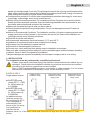
3.1 IPC-2 / IPC-3
Single-phase Inverter
decline for average speed in one day. This prolongs the service life of pump and eliminates water
eect. Water hammer eect means direct starting and stopping, liquid kinetic energy of a hammer
sharp change thus leading to a great impact of the network.
l Comprehensive protection: It has the most comprehensive protection technology for overcurrent,
overvoltage, undervoltage, short circuit, locked-rotor etc.
l Safety and environmental protection: Full compliance with the European Union and the United
States and other developed countries. High manufacturing standards and requirements for pro-
duct safety and environmental protection are observed.
l Make sure the model and type is what you have ordered .
l Check whether the product during transportation. Do not use damaged products!! Contact us
immediately.
l Notice for Environmental Conditions. The installation condition of inverter constant pressure water
supply system have a direct impact on the function and service life. Ensure that installation sur-
roundings conform to the following conditions:
l Products should be used indoors
l Environmental temperature should be between -10°C and +40°C
l Installation environment should be well ventilated but not damp.
l Stay away from the radioactive material and fuel
l Prevention of electromagnetic interference
l Prevent dust, cotton and metal from getting close to installation environment
Make sure after unpacking that the data given on the nameplate agree with the foreseen operating
conditions. When in doubt, the operation is prohibited.
Transport damages are reported immediately to the transport company and to us in writing.
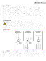
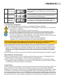
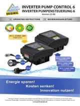
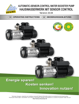
Water booster
installation mode
Self-priming pump
installation of water
supply mode
Submersible pump
installation of water
supply mode
l INVERTER pump
control IPC-2, 1,1KW
for 230V pumps up
to 1100Watt.
l INVERTER pump
control IPC-3, 2.2KW
for 230V pumps up
to 2200Watt.
An additional pump
(auxilary pump) can
be connected to IPC-3.
This is switched on
automatically if the
power of the 1st pump
is not sucient to
maintain the set
pressure value (i.e. if the water withdrawal becomes too large and the set pressure is fallen
below).

4 English
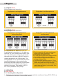
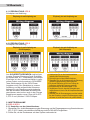
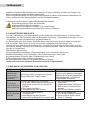
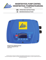
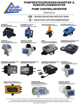
4.1 WIRING: IPC-2
Wiring Diagram and Instruction
Single-phase in and single-phase out Single-phase in and three-phase out
4.2 WIRING: IPC-3
Wiring Diagram and Instruction
Single-phase in and single-phase out
(with auxiliary pump)
Single-phase in and three-phase out
(auxiliary pump)
1. Don‘t connect the AC main circuit power
supply and output terminals U, V, W.
2. Wiring after the power cut o.
3. To verify the inverter rated voltage and the
input supply voltage are consistent
4. The inverter can‘t be done the dielectric
voltage withstand Test.
5. Terminal screw tightening torque 1.7N.m.
6. Make sure the ground terminal is connected
before wiring the main circuit terminals.
7. Connect the input power after installing the
panel,when the power is connected, don‘t
remove the panel
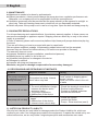
5. OPERATION
5.1 IPC-2 / IPC-3
5.1.1 Checking before Operation
1. Check the input power and surroundings is comply with the conditions of using. IPC-2 / IPC-3 are
not intended for 380-400V in the current version.
For REASONS OF SAFETY, there are
2 earth/ground connections, i.e. 4 cable con-
nections, for your inverter pump control. One
wire is in yellow-green colour, as usual inter-
nationally, and the other in BLACK (which is
usually assigned for the 230V phase). The
wiring diagram in our manual and the printed
terminal assignment in the control clearly
shows that the black cable core is connected
to ground and must therefore also be con-
nected in the pump. This applies to IPC-2,
IPC-3 and „standard“ 230V pumps.

English 5
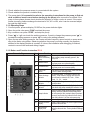
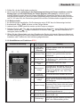
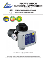
5.1.2 Button and Function Instruction IPC-3
Schematic Diagram No. Name or Function Instruction
1Start or stop
button of auxiliary
pump
Start auxiliary pump manually, press it, the
pump runs
2 Reduce button Press the button one time can reduce 0.1bar,
long time press can reduced rapidly
3 Increase button Press the button one time can increase 0.1bar,
long time press can increase rapidly
4RUN/STOP
button It can start the pump manually, press this button
to exit the water shortage state
5Water shortage
indicator
The indicator ash , it means the pipe is wa-
tershort. It will restart in setting time and the
interval time for restart is 8S, 1min , 10min ,
30min , 1h , 2h ....restart
6Pressure setting
indicator The light is ashing when working in the setting
pressure value
7auxiliary pump
indicator When the pump stop automatically,the indicator
lights,when stop pump manually,the indicator is off
8 Pump indicator
When the main pump speed operating state or
standby state,the indicator ash quickly.when
the main pump at the constant speed (constant
pressure) work state, the indicator ash slowly.
when the indicator is off,the main pump stop
9 Power indicator Indicator lights up when power is connected.
10 Current pressure
display Display value indicates the current pipe network
pressure value,unit:bar
11 Set pressure
display area
Display value indicates the current setting
pressure value,unit:bar. Factory default Settings
is 3bar
2. Check whether the pressure sensor is connected with the system .
3. Check whether the product is installed rmly .
4. The pump starts (it is essential to refer to the operating instructions for the pump to nd out
what conditions must be met before starting up the pump) after connection is veried. If the
pump is three phase, please check whether the direction of motor revolve is correct. If the motor
rotates inversely, please exchange the terminal of UV, WV or WU, also it can be reversed adjust
through the slide switch.
5.1.2 Operating Steps
1. Connect power ,pressure display “00.00”bar, the power indicator lights.
2. Open the outlet valve,press “RUN” and start the pump
3. Any conditions can press “STOP”, and stop the pump
4. Press “ ” or “ ” can check the working pressure, if want to change the pressure press “ ” to
increase the setting pressure or press “ ” to reduce the setting pressure
5. Open the tap after setting pressure, the inverter will take frequency speed control on pump accor-
ding to the water using status .Observing whether the pump is running normally, the pressure
showed in the display whether is constant. If it does, the installation and debugging is nished,
content to remove the faults and debug it again .

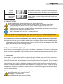
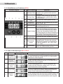
No. Code name Schematic Diagram Instruction
1Over-Voltage
protection When the voltage is higher than 270V shows this code, if the Vol-
tage is lower than 260V, then recover to normal working situation
2Under-Voltage
protection When the voltage is lower than 100V shows this code, if the Vol-
tage is higher than 110V, then recover to normal working situation
3Thermal
protection
When radiator temperature get to 80 °C shows this code,if the
temperature lower than 60 °C,then recover to normal working
situation
4 Sensor error When pressure sensor damaged or disconnect shows this code,
recover to normalworking situation after people check trouble-
shooting
5Over pressure
protection
When pipe pressure equal to 99% of pressure sensor pressure
shows this code,if the the pressure lower than 96% of the pressure
sensor pressure,then recover to normal working situation
6Open phase
protection
When inputed three phase power open phase shows this code,
recover to normal working situation after people check trouble-
shooting
7Overload
protection When exceed the setcurrent or load power shows this code, reco-
ver to normal working situation after people check troubleshooting
8Over-current
or short circuit
protection
When motor with short circuit or over-current problems shows
this code, recover to normal working situation after people check
troubleshooting
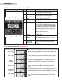
5.1.4 Code and Instruction IPC-2 / IPC-3
5.1.3 Button and Function Instruction IPC-2
Schematic Diagram No. Name or Function Instruction
1 Reduce button Press the button one time can reduce 0.1bar,
long time press can reduced rapidly
2 Increase button Press the button one time can increase 0.1bar,
long time press can increase rapidly
3RUN/STOP
button It can start the pump manually, press this button
to exit the water shortage state
4Current pressure
display Display value indicates the current pipe network
pressure value,unit:bar
5 Power indicator Indicator lights up when power is connected.
6 Pump indicator
When the main pump speed operating state
or when motor is in speed governing state,the
indicator ash quickly. When the main pump at
the constant speed work state or water shor-
tage, the indicator ash slowly. When it stop
automatically,the indicator is on. When it stop
manually ,the indicator is off.
7Pressure setting
indicator The light is ashing when working in the setting
pressure value
8Water shortage
indicator
The indicator ash , it means the pipe is wa-
tershort. It will restart in setting time and the
interval time for restart is 8S, 1min , 10min ,
30min , 1h , 2h ....restart
9Set pressure
display area
Display value indicates the current setting
pressure value,unit:bar. Factory default Settings
is 3bar
6 English

6. SECURITY TIPS
l Obey absolutely valid regulations on the electrical security
l To avoid shocks and re risks, read and follow closely the following instructions:
• Always unplug the device from the mains before carrying out any work on it.
• Be sure that the electric line connecting the device to the mains and the extension
leads have a cross-section suitable for pump power and be sure that the electrical con-
nections are far away from any water source
• When Flow guard is used for swimming pools, ponds and fountains if is necessary to
use an automatic RCD with IDn = 3OmA protection.
Warning: when the pump stops, the pipes are under pressure consequently we recom-
mend opening a tap to discharge the system before carrying out any work.
l The electrical connections are always to be carried out by an authorised professional.
l The device may be used by children aged 8 years and above as well as persons with reduced
physical, sensory or mental abilities or those who lack skills, experience and knowledge only if
they are supervised. These aforementioned persons should only use the appliance while adhe-
ring to safe instructions and resulting dangers.
l Cleaning and maintenance must not be carried out by children without supervision.
THE MANUFACTURER EXPLAINS:
l To take over no responsibility in the case of accidents or damages on the basis of carelessness
or disregard to the instructions in this book.
l To reject every responsibility for the damages which originate from the improper use of the device.
No. Code name Schematic Diagram Instruction
1Over-Voltage
protection When the voltage is higher than 270V shows this code, if the Vol-
tage is lower than 260V, then recover to normal working situation
2Under-Voltage
protection When the voltage is lower than 100V shows this code, if the Vol-
tage is higher than 110V, then recover to normal working situation
3Thermal
protection
When radiator temperature get to 80 °C shows this code,if the
temperature lower than 60 °C,then recover to normal working
situation
4 Sensor error When pressure sensor damaged or disconnect shows this code,
recover to normalworking situation after people check trouble-
shooting
5Over pressure
protection
When pipe pressure equal to 99% of pressure sensor pressure
shows this code,if the the pressure lower than 96% of the pressure
sensor pressure,then recover to normal working situation
6Open phase
protection
When inputed three phase power open phase shows this code,
recover to normal working situation after people check trouble-
shooting
7Overload
protection When exceed the setcurrent or load power shows this code, reco-
ver to normal working situation after people check troubleshooting
8Over-current
or short circuit
protection
When motor with short circuit or over-current problems shows
this code, recover to normal working situation after people check
troubleshooting
7. SERVICING
It may happen occasionally that dirt is retained in the internal check valve and this is no longer
seals 100%. The rst remedy should be always trying to ush the check valve free. For this pur-
pose, eg. As the Garden side faucet on full blast, so that the pump at full rated power promotes
about 30 minutes water. Is then the timing is not clear, the unit must be replaced. Prior to installati-
on of the new device, the pump is in, free to ush any case, as previously described. Opening the
device on non-return valve is prohibited and always results in the loss of any existing warranty. In
addition, persons could be dangerous when Operating a clocking pump occur, so that the pump
may be operated under any circumstances continue. Until the device replacement, the pump must
be taken out of service. For abrasive materials such as sand, shortening the Maintenance period
and the device lifetime.
The following checks should be carried out regularly:
l functional test (min. every 3 months)
l integrity of the power cord
l Clean the guide lines (eg no buckling)
l Clean the media (no sand, no sludge)
English 7

9. GUARANTEE REGULATIONS
For all manufacturing and material defects, the statutory warranty applies. In these cases, we
assume the exchange or appliance repairs. Shipping costs are borne by us only to the extent
legally is prescribed.
In case of warranty please call our service platform http://www.pro-pumpe.de/service.php log
the event.
Then we will inform you how to proceed with case by case basis.
Returns please sucient postage. Unfortunately prepaid returns will not be accepted,
because they are ltered out before delivery. Our service we provide in Germany.
The warranty does not cover:
l Improper installation (proper installation, unauthorized persons)
l Material wear (eg. seals) or dirt in the unit
l Unjustied interventions or changes in the device
l Damages by selault
l Improper servicing and improper use
Moreover, we give no damage compensation for secondary damages!
8 English
10. RECOGNISING AND REPAIRING OF MISTAKES
Problem Mögliche Ursache Lösung
The pump permanent-
ly switches on and o
(Pump clocked)
The system has leaks. Internal
check valve may leak
Vent system
Check system to dripping pipes /
faucets / valves.
Check non-return valve in the unit
for leaks
The pump will not start
1. No mains voltage present
2. Too much dierence in height
between the device and a
customer (taps)
3. The pump is defective
4. Malfunction of the device
1. Check the electrical connections
2. Reduce height dierence
3. Contact a qualied technician
4. Montact the merchant
The pump will not stop
1. The system has greater lea-
kages
2. Malfunction of the device
3. Internal check valve is dirty
1. Check the system
2. contact the dealer
3. Pump + Rinse machine (see 6)
8. MAINTENANCE
l Maintenance needs to be done by professionals.
l Without permission, clients cannot change the pump structure, regulation performance etc.
Otherwise, our company will not be responsible for all the consequences.
l Ventilation measures must be provided but the pump should not be exposed to sunlight. or
direct rain. Take anti freezing measures in winter but not use ammable materials.
l Switch o power if the pump is not in use for a long time. Open the bolt and keep pump dry.
11. NOTES ON PRODUCT LIABILITY
We point out, that we are only liable for damages under the Product Liability Act, which are
caused by our units if no changes were made to the equipment. If repairs are carried out by our
authorized service, we are only liable if original spare parts and accessories were used.

English 9
12. NOTES ON DISPOSAL
Electro devices of our company, labeled with the symbol of the crossed trash bin, are
not permitted to be disposed in your household garbage. We are registered at the
German registration department EAR under the WEEE-No. DE25523173.
This symbol means, that you’re not allowed to treat this product as a regular
household waste item – it has to be disposed at a recycling collection point of electri-
cal devices. This is the best way to save and protect our earth.
THANK YOU FOR YOUR SUPPORT!
13. EU DECLARATION OF CONFORMITY
The products listed overleaf accordance with the marketed in accordance with the relevant
provisions listed below, the relevant EU directives and harmonized with EU standards for safety.
This declaration is valid insofar on the product, no changes are made.
Authorized person to keep the technical documents:
1A-Pro-Handels GmbH · Unterriethstraße 37 · D-65187 Wiesbaden
Low Voltage Directive (2014/35/EU)
EC Electromagnetic compatibility directive (2014/30/EU)
The following harmonized standards:
EN 61800-5-1:2007
EN 62233:2008+AC:2008
EN 61000-6-1:2007
EN 61000-6-3:2007+A1:2011
EN 61000-3-2:2014
EN61000-3-3:2013
Wiesbaden, 12th August 2017
ppa. Peter Neumüller

Inhaltsverzeichnis
1. Vorwort .............................................................................................................................. 10
2. Allgemeines ...................................................................................................................... 11
3. Installation ......................................................................................................................... 11
4. Verdrahtung ...................................................................................................................... 12
5. Inbetriebnahme ................................................................................................................. 12
6. Sicherheitshinweise .......................................................................................................... 15
7. Wartung ............................................................................................................................ 15
8. Garantiebestimmungen .................................................................................................... 16
9. Erkennen und Beheben von Fehlern ................................................................................ 16
10. Hinweise zur Produkthaftung ............................................................................................ 17
11. Entsorgungshinweise ........................................................................................................ 17
12. EU-Konformitätserklärung ................................................................................................ 17
13. Technische Daten ............................................................................................................. 20
SICHERHEITSHINWEISE UND WARNUNGEN
Bitte lesen Sie vor Inbetriebnahme des
Geräts die Bedienungsanleitung Netzstecker ziehen
Allgemeines Warnzeichen Warnung vor elektrischer Spannung
10 Deutsch
1. VORWORT
Zum Kauf unserer Inverter Pumpensteuerung möchten wir Sie recht herzlich beglückwünschen.
Wir wissen Ihr Vertrauen zu schätzen. Aus diesem Grund stehen bei uns Funktions- und Be-
triebssicherheit an erster Stelle.
Um Personen- und Sachschäden zu vermeiden, lesen Sie die vorliegende Bedie-
nungsanleitung bitte aufmerksam durch. Bitte beachten Sie alle Sicherheitshin-
weise und Anweisungen zum sachgemäßen Gebrauch der Pumpensteuerung.
Eine Nichtbeachtung der Anweisungen und Sicherheitshinweise können zu
körperlichen Schäden oder zu Sachschäden führen.
Bitte bewahren Sie die Bedienungsanleitung mit den Anweisungen und Sicher-
heitshinweisen sorgfältig auf, um jederzeit darauf zurückgreifen zu können.
Bitte laden Sie stets die neueste Ausführung der Bedienungsanleitung von
www.pro-pumpe.de unter „download“ herunter. Diese ist stets maßgebend.

2. ALLGEMEINES
Die Inverter Pumpensteuerung ist ein Schaltgerät, welches einen elektrischen Verbraucher
(Pumpe) automatisch Ein- und Ausschalten kann. Das Gerät überwacht den Druck und den
Durchuß in der Druckleitung. Abhängig von dem Druck bzw. der Durchussmenge, schaltet
der Inverter Pumpensteuerung einen oder mehrere elektrische Verbraucher (MAX 10A) an bzw.
aus.
Die Inverter Pumpensteuerung ist ausschließlich für nicht abrasives Klarwasser ohne Ablage-
rungen und sonstigen Schmutz einzusetzen. Im gegenteiligen Fall muss ein wirksamer Vorlter
mit Maschenweite nicht gröber als 0,2mm vor dem Gerät eingebaut werden.
Vergewissern Sie sich nach dem Auspacken, dass die auf dem Typenschild angegebenen
Daten mit den vorgesehenen Betriebsbedingungen übereinstimmen. Im Zweifelsfall ist der Be-
trieb zu unterlassen.
Transportschäden sind unverzüglich dem Speditionsunternehmen und uns schriftlich mitzuteilen.
Deutsch 11
3. INSTALLATION
Die Installation ist von einer qualizierten Fachkraft auszuführen.
Bitte überprüfen Sie vor jeder Inbetriebnahme die elektrischen Anschlüsse sowie das
Kabel auf Unversehrtheit. Bitte prüfen Sie vor der Installation, ob der elektrische An-
schluss entsprechend der gesetzlichen Vorschriften geerdet und installiert ist.
Es ist NICHT zu empfehlen selbst Kabelverlängerungen oder andere technische Modi-
kationen durchzuführen. Erstens ist nicht sichergestellt, ob diese Veränderungen tech-
nisch einwandfrei sind und zweitens kann dadurch keine Garantie gewährt werden.
3.1 IPC-2 / IPC-3
Einphasen-Inverter Einbaubeispiel
Hauswasserwerk
Einbaubeispiel
Selbsansaugende
Pumpen
Einbaubeispiel
Tauchpumpe
l INVERTER-Pumpensteuerung IPC-2, 1,1KW - für 230V-Pumpen bis 1100Watt.
l INVERTER-Pumpensteuerung IPC-3, 2,2KW - für 230V-Pumpen bis 2200Watt.
Bei IPC-3 kann eine Zusatz-Pumpe (Auxilary pump) angeschlossen werden. Diese schaltet sich
automatisch zu, wenn die Leistung der 1. Pumpe nicht ausreicht um die eingestellten Druckwert
aufrecht zu halten (also wenn die Wasserentnahme zu groß wird und dadurch der Solldruck
unterschritten wird).

4.2 VERDRAHTUNG: IPC-3
Schaltplan und Anleitung
4.1 VERDRAHTUNG: IPC-2
Schaltplan und Anleitung
Einphasig ein und einphasig aus
(mit Hilfspumpe)
Einphasig ein und dreiphasig aus
(mit Hilfspumpe)
1. Unterbrechen Sie vor den Anschlussarbeiten
unbedingt die Stromversorgung.
2. Sie können jetzt mit den Arbeiten beginnen.
3. Überprüfen Sie, ob die Nennspannung der Steuerung
und die Eingangsspannung übereinstimmen
4. Die Inverter-Steuerung ist nicht zur Prüfung der
zulässigen elektrischen Spannung geeignet.
5. Anzugsmoment der Klemmschraube 1,7 Nm
6. Vergewissern Sie sich, dass die Erdungsklemme
angeschlossen ist, bevor Sie die Hauptstromklemmen
verdrahten.
7. Schließen Sie die Stromversorgung nach der Installa-
tion des Panels an, wenn die Stromversorgung ange-
schlossen ist, sollte das Panel nicht geöffnet werden.
5. INBETRIEBNAHME
5.1 IPC-2 / IPC-3
5.1.1 Kontrollen vor der Inbetriebnahme
1.
Überprüfen Sie, ob die Nennspannung der Steuerung und die Eingangsspannung übereinstimmen.
IPC-2 / IPC-3 sind in der aktuellen Ausführung nicht für 380-400V vorgesehen.
2. Prüfen Sie, ob der Drucksensor mit dem System verbunden ist.
12 Deutsch
Einphasig ein und einphasig aus Einphasig ein und dreiphasig aus
Aus SICHEREITSGRÜNDEN sind bei ihrer
Inverter Pumpen-Steuerung 2mal Erde/Mas-
se-Anschlüsse, d.h. 4 Kabeladern vorhanden.
Eine Ader ist, wie international üblich in gelb-
grüner Farbe, und die andere in SCHWARZ
(was üblicherweise für die 230V-Phase
vergeben wird). Der Schaltplan in unserer
Anleitung und die aufgedruckte Klemmen-
belegung in der Steuerung zeigt eindeutig,
daß die schwarze Kabelader an Masse an-
geschlossen wird und so auch in der Pumpe
angeklemmt werden muss. Dies gilt für IPC-
2, IPC-3 und „üblichen“ 230V-Pumpen.

5.1.2 Schaltächen und Funktionen IPC-3
Schematische Darstellung Nr. Bezeichnung
oder Funktion Anleitung
1Start- oder
Stopptaste der
Hilfspumpe
Hilfspumpe manuell starten, die Taste drücken,
die Pumpe läuft an
2Reduzieren-Taste Einmaliges kurzes Drücken der Taste senkt den
Druck um 0,1 bar, gedrückt halten senkt den
Druck schnell.
3Erhöhen-Taste Einmaliges kurzes Drücken der Taste erhöht
den Druck um 0,1 bar, gedrückt halten erhöht
den Druck schnell.
4START/STOP-
Taste Zum manuellen Starten der Pumpe
5Wassermangel-
Anzeige
Die Anzeige blinkt, das bedeutet, dass ein Was-
sermangel besteht. Es wird in der voreinege-
stellten Zeit neu gestartet. Die Schaltzeiten für
den Neustart beträgt 8S, 1min, 10min, 30min,
1h, 2h....restart
6Druckeinstel-
lungsanzeige Die Leuchte blinkt beim Enstellen des Drucks
7Zusatzpumpen-
anzeige
Wenn die Pumpe automatisch stoppt, leuchtet die
Anzeige, wenn die Pumpe manuell gestoppt wird,
ist die Anzeige aus.
8Pumpen-Anzeige
Wenn die Hauptpumpe mit konstanter Drehzahl
(konstantem Druck) arbeitet, blinkt die Anzeige
langsam. Wenn die Anzeige ausgeschaltet ist,
stoppt die Hauptpumpe.
9Leistungsanzeige Die Anzeige leuchtet, wenn das Gerät an das
Stromnetz angeschlossen ist.
10 Anzeige des
aktuellen Drucks Anzeigewert gibt den aktuellen Druck im Rohr-
netz an, Einheit = bar
11 Druckanzeige Anzeigewert zeigt den aktuellen Einstelldruck,
Einheit = bar. Werkseinstellung ist 3bar
Deutsch 13
3. Prüfen Sie, ob das Gerät sicher montiert ist.
4. Die Pumpe läuft an (unbedingt in der Bedienungsanleitung der Pumpe nachlesen, welche
Bedingungen vor Inbetriebnahme der Pumpe gegeben sein müssen), nachdem der An-
schluss überprüft wurde. Wenn die Pumpe dreiphasig ist, überprüfen Sie bitte, ob die Drehrich-
tung des Motors korrekt ist. Wenn der Motor gegenläug dreht, tauschen Sie bitte den Anschluss
von UV, WV oder WU, die Drehrichtung kann auch mit dem Schiebeschalter eingestellt werden.
5.1.2 Bedienschritte
1. An das Stromnetz anschließen. Die Druckanzeige zeigt „00.00“ bar, die Netzanzeige leuchtet.
2. Auslassventil önen, „RUN“ drücken und die Pumpe starten.
3. Jederzeit kann „STOP“ gedrückt werden und die Pumpe zu stoppen.
4. Drücken Sie kurz „ “ oder „ “, um den Arbeitsdruck zu überprüfen, wenn Sie den Druck ändern
möchten, halten Sie „ “, um den Einstelldruck zu erhöhen oder „ “, um den Einstelldruck zu
verringern (siehe auch 5.1.2).
5. Önen Sie den Wasserhahn nach dem Einstellen des Drucks, die Inverter-Steuerung übernimmt
die Drehzahlregelung der Pumpe entsprechend dem Wasserbedarf. Wenn dies der Fall ist, ist die
Installation oder Fehlersuche und -behebung abgeschlossen.

5.1.3 Schaltächen und Funktionen IPC-2
Schematic Diagram No. Name or Function Instruction
1Reduzieren-Taste Einmaliges kurzes Drücken der Taste senkt den
Druck um 0,1 bar, gedrückt halten senkt den
Druck schnell.
2Erhöhen-Taste Einmaliges kurzes Drücken der Taste erhöht
den Druck um 0,1 bar, gedrückt halten erhöht
den Druck schnell.
3START/STOP-
Taste Die Pumpe kann manuell gestartet werden
4Anzeige des
aktuellen Drucks Anzeigewert gibt den aktuellen Druck im Rohr-
netz an, Einheit = bar
5Leistungsanzeige Die Anzeige leuchtet, wenn das Gerät an das
Stromnetz angeschlossen ist.
6Pumpen-Anzeige
Wenn sich die Hauptpumpe im drehzahlre-
gelnden Zustand bendet, blinkt die Anzeige
schnell. Wenn die Hauptpumpe bei konstanter
Drehzahl oder Wassermangel arbeitet, blinkt
die Anzeige langsam. Bei einem automatischen
Stopp leuchtet die Anzeige dauerhaft. Wird ma-
nuell gestoppt, ist die Anzeige ausgeschaltet.
7Druckeinstel-
lungsanzeige Die Leuchte blinkt beim Enstellen des Drucks
8Wassermangel-
Anzeige
Die Anzeige blinkt, das bedeutet, dass ein Was-
sermangel besteht. Es wird in der voreinege-
stellten Zeit neu gestartet. Die Schaltzeiten für
den Neustart beträgt 8S, 1min, 10min, 30min,
1h, 2h....restart
9Druckanzeige Anzeigewert zeigt den aktuellen Einstelldruck,
Einheit = bar. Werkseinstellung ist 3bar
No. Code name Schematic Diagram Instruction
1Überspan-
nungsschutz
Wenn die Spannung höher als 270V ist, wird dieser Code ange-
zeigt, wenn die Spannung niedriger als 260V ist, ist die normale
Arbeitssituation wieder hergestellt.
2Unterspan-
nungsschutz
Wenn die Spannung niedriger als 100V ist, wird dieser Code
angezeigt, wenn die Spannung höher als 110V ist, ist die normale
Arbeitssituation wieder hergestellt.
3Thermischer
Schutz
Wenn die Wassertemperatur 80 °C erreicht, wird dieser Code
angezeigt, wenn die Temperatur niedriger als 60 °C ist, ist die
normale Arbeitssituation wieder hergestellt.
4 Sensor-Fehler Wenn der Drucksensor beschädigt ist oder die Verbindung unter-
brochen wird, stellen Sie die normale Arbeitssituation wieder her,
nachdem Sie die Fehlerbehebung durchgeführt haben.
5Überdruck-
Schutz
Wenn der Leitungsdruck 99% des Drucks des Drucksensors beträgt, wird
dieser Code angezeigt. Wenn der Druck niedriger als 96% des Drucks
des Drucksensors ist, ist die normale Arbeitssituation wieder hergestellt.
6Open phase
protection
When inputed three phase power open phase shows this code,
recover to normal working situation after people check trouble-
shooting
7Overload
protection When exceed the setcurrent or load power shows this code, reco-
ver to normal working situation after people check troubleshooting
8Over-current
or short circuit
protection
When motor with short circuit or over-current problems shows
this code, recover to normal working situation after people check
troubleshooting
5.1.4 Code und Anweisungen IPC-2 / IPC-3
14 Deutsch

No. Code name Schematic Diagram Instruction
1Over-Voltage
protection When the voltage is higher than 270V shows this code, if the Vol-
tage is lower than 260V, then recover to normal working situation
2Under-Voltage
protection When the voltage is lower than 100V shows this code, if the Vol-
tage is higher than 110V, then recover to normal working situation
3Thermal
protection
When radiator temperature get to 80 °C shows this code,if the
temperature lower than 60 °C,then recover to normal working
situation
4 Sensor error When pressure sensor damaged or disconnect shows this code,
recover to normalworking situation after people check trouble-
shooting
5Over pressure
protection
When pipe pressure equal to 99% of pressure sensor pressure
shows this code,if the the pressure lower than 96% of the pressure
sensor pressure,then recover to normal working situation
6 Offene Phase Wenn die eingegebene dreiphasige offene Phase diesen Code
anzeigt, stellen Sie nach der Fehlersuche die normale Arbeitssitua-
tion wieder her.
7Überlastschutz Wenn der eingestellte Strom oder die Lastleistung überschritten
wird, wird dieser Code angezeigt, nach der Fehlersuche wird die
normale Arbeitssituation wiederhergestellt.
8Überstrom-
oder Kurz-
schlussschutz
Wenn ein Motor mit Kurzschluss- oder Überstromproblemen die-
sen Code anzeigt, Sie die normale Arbeitssituation wieder herstel-
len, nachdem Sie eine Fehlerdiagnose durchgeführt haben.
6. SICHERHEITSHINWEISE
l Unbedingt geltende Vorschriften zur elektrischen Sicherheit befolgen
l Um elektrische Schläge zu vermeiden und Brandgefahr vorzubeugen, ist das Folgende
genauestens zu beachten:
- Das Gerät vor jedem Eingri vom Stromnetz trennen
- Sicherstellen, dass die Anschlussleitung an das Stromnetz und eventuelle Verlän-
gerungen einen Kabelquerschnitt haben, der für die Leistung des Geräts geeignet ist,
sowie das die elektrischen Anschlüsse nicht vom Wasser erreicht werden können
- Im Fall von Gebrauch in Schwimmbädern, Teichen oder Brunnen immer einen automa-
tischen Dierentialschalter (FI) mit lDn=30mA verwenden
- Gerät nicht dauerhaft in der Sonne betreiben (Überhitzungsgefahr).
- Installation nur in frostsicheren Bereichen ohne Kondensatbildung
Achtung: Wenn die Pumpe stoppt, stehen die Leitungen unter Druck, deshalb empfehlen
wir, vor allen Arbeiten einen Wasserhahn zu önen, um die Anlage zu entleeren.
l Der elektrische Anschluss ist stets durch einen autorisierten Fachmann vorzunehmen.
l Der Druckwächter darf von Kindern ab 8 Jahren sowie von Personen mit verringerten phy-
sischen, sensorischen oder mentalen Fähigkeiten oder aufgrund mangelnder Erfahrung und
Wissen nur unter Beaufsichtigung benutzt werden oder wenn diese bezüglich des sicheren
Gebrauchs des Gerätes unterwiesen worden sind und die daraus resultierenden Gefahren
verstehen.
l Die Reinigung und Wartung darf nicht von Kindern ohne Beaufsichtigung durchgeführt werden.
DER HERSTELLER ERKLÄRT,
l Keine Verantwortung im Fall von Unfällen oder Schäden aufgrund von Fahrlässigkeit oder
Missachtung der Anweisungen in dieser Anleitung zu übernehmen
l Jede Verantwortung für Schäden, die durch die unsachgemäße Verwendung des Inverter
Pumpensteuerung und Mißachtung von geltenden EN,- DIN-Normen sowie anderer Normen
und Standes der Technik entstehen, abzulehnen
7. WARTUNG
Es kann gelegentlich vorkommen, dass Schmutz im internen Rückschlagventil hängen bleibt und
dieses nicht mehr 100% abdichtet. Als erste Abhilfe sollte immer versucht werden, das Rück-
schlagventil frei zu spülen. Dazu wird z. B. der gartenseitige Wasserhahn voll aufgedreht, so dass
die Pumpe ca. 30 Minuten auf voller Leistung Wasser fördert. Ist anschließend das Takten nicht
weg, ist das Gerät zu tauschen. Vor dem Einbau des neuen Gerätes, ist die Pumpe in jedem Fall
wie vorher beschrieben, frei zu spülen. Das Önen des Gerätes am Rückschlagventil ist unzuläs-
sig und führt stets zum Verlust der ggf. bestehenden Garantieansprüche. Darüber hinaus können
Deutsch 15

Problem Mögliche Ursache Lösung
Die Pumpe
schaltet sich
dauernd ein
und aus (Pum-
pe taktet)
Die Anlage weist Leckagen auf Internes
Rückschlagventil ist ggf. undicht
System entlüften
System auf tropfende Leitungen/
Wasserhähne/Ventile überprüfen.
Rückschlagventil im Gerät auf
Undichtigkeit überprüfen
Die Pumpe
setzt sich nicht
mehr in Betrieb
1. Keine Netzspannung vorhanden
2. Zu großer Höhenunterschied zwischen
dem Gerät und einem der Abnehmer
(Hähne)
3. Die Pumpe ist defekt
4. Betriebsstörung des Gerätes
1. Die Elektroanschlüsse
überprüfen.
2. Höhenunterschied Verringern
3. Sich an einen Fachtechniker
wenden
4. Sich an den Händler wenden
Die Pumpe hält
nicht an
1. Die Anlage weist größere
Leckagen auf
2. Betriebsstörung des Gerätes
3. Internes Rückschlagventil ist verschmutzt
1. Die Anlage überprüfen
2. Sich an den Händler wenden
3. Pumpe+Gerät spülen (siehe
Punkt 6. Wartung)
9. ERKENNEN UND BEHEBEN VON FEHLERN
8. GARANTIEBESTIMMUNGEN
Für alle Fabrikations- und Materialfehler gilt die gesetzliche Gewährleistung. In diesen Fällen
übernehmen wir den Umtausch oder die Reparatur des Geräts. Versandkosten werden von uns
nur getragen, soweit dies gesetzlich vorgeschrieben ist.
Im Garantiefall bitte über unsere Serviceplattform http://www.pro-pumpe.de/service.php den
Fall anmelden. Dann teilen wir Ihnen die weitere Vorgehensweise fallbezogen mit.
Rücksendungen bitte ausreichend frankieren. Unfreie Rücksendungen können leider nicht an-
genommen werden, da diese vor Zustellung rausgeltert werden. Unsere Serviceleistung erbrin-
gen wir in Deutschland.
Die Garantie gilt nicht bei:
l Unsachgemäßer Installation (Eigeninstallation, nicht autorisierte Personen)
l Materialverschleiß (z.B. Dichtungen) oder Schmutzeintrag in das Gerät
l Unberechtigten Eingrien oder Veränderungen am Gerät
l Beschädigungen durch Selbstverschulden
l Unsachgemäßer Wartung und unsachgemäßem Betrieb
Außerdem leisten wir keinerlei Schadensersatz für Folgeschäden!
erhebliche Gefahren beim Betrieb einer taktenden Pumpe entstehen, so dass die Pumpe unter
keinen Umständen weiter betrieben werden darf.
Bis zum Geräteaustausch ist die Pumpe außer Betrieb zu setzen. Bei abrasiven Materialien wie
Sand, verkürzt sich die Wartungsdauer und die Gerätelebensdauer.
Folgende Kontrollen sollten regelmäßig durchgeführt werden:
l Funktionsprüfung (mind. alle 3 Monate)
l Unversehrtheit des Stromkabels
l Saubere Führung der Leitungen (z.B. keinen Knick)
l Sauberkeit des Mediums (keinen Sand, keinen Schlamm)
16 Deutsch

10. HINWEISE ZUR PRODUKTHAFTUNG
Wir weisen darauf hin, dass wir nach dem Produkthaftungsgesetz für Schäden, die durch unsere
Geräte verursacht werden, nur insofern haften, soweit keine Veränderungen an den Geräten
vorgenommen wurden. Falls Reparaturen durch von uns autorisierte Servicewerkstätte vorgenom-
men werden, haften wir nur insofern, wenn Original-Ersatzteile und Zubehör verwendet wurden.
11. ENTSORGUNGSHINWEISE
Elektro-Geräte mit dem Symbol der durchgestrichenen Mülltonne dürfen nicht über
den Hausmüll entsorgt werden, sondern sind an einer Annahmestelle für Recycling
von elektronischen Geräten abzugeben. Bei der deutschen Registrierungsstelle
EAR sind wir unter der WEEE-Nummer DE25523173 gelistet.
So tragen Sie zur Erhaltung und zum Schutz unserer Umwelt bei.
VIELEN DANK FÜR IHRE UNTERSTÜTZUNG!
12. EU-KONFORMITÄTSERKLÄRUNG
Die umseitig benannten Produkte entsprechen der in den Verkehr gebrachten Ausführung den
unten aufgeführten einschlägigen Bestimmungen, den entsprechenden EU harmonisierten Richt-
linien und dem EU-Standard für Sicherheit. Diese Konformitätserklärung gilt, insofern an dem
Produkt keine Veränderungen vorgenommen werden.
Autorisierte Person zur Aufbewahrung der technischen Dokumente:
1A-Pro-Handels GmbH · Unterriethstraße 37 · D-65187 Wiesbaden
Richtlinie Niederspannung (2014/35/EU)
Richtlinie Elektromagnetische Verträglichkeit (2014/30/EU)
Folgende harmonisierte Normen:
EN 61800-5-1:2007
EN 62233:2008+AC:2008
EN 61000-6-1:2007
EN 61000-6-3:2007+A1:2011
EN 61000-3-2:2014
EN61000-3-3:2013
Wiesbaden, den 12.08.2017
ppa.Peter Neumüller
Deutsch 17

18 Notes

Notizen 19

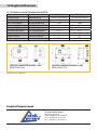
English Deutsch PSM01134U PSM01135U
Tension/Voltage Betriebsspannung 220/240V bei 50/60Hz 220/240V bei 50/60Hz
Max. Current Max. Nennstrom 6A 9,6A
Max. Power demand Max Anschlussleistung 1,1KW 2,2KW
Max. working Pressure Max. Betriebsdruck 10bar 10bar
Max. operating Pressure Max. Arbeitsdruck 1-9bar 1-9bar
Max water temperature Max. Wassertemperatur 50 °C 50 °C
Input connector Anschlüsse Eingang 1” 1,25”
Output connector Anschlüsse Ausgang 1” 1,25”
Protection-grade Schutzart IP54 IP54
12 Englisch/Deutsch
Imprint/Impressum
1A Pro Handels GmbH
www.pro-pumpe.de
Email: info@1a-pro-handel.de
Tel.: (+49) 0611-9 45 87 76-0
Fax: (+49) 0611-9 45 87 76-11
de
12. TECHNICAL DATA/TECHNISCHE DATEN
INVERTER-PUMPENSTEUERUNG 2-1,1KW
(IPC-2) (PSM01134U)
Dimensions in mm / Maße in mm
INVERTER-PUMPENSTEUERUNG 3-2,2KW
(IPC-3) (PSM01135U)
-
 1
1
-
 2
2
-
 3
3
-
 4
4
-
 5
5
-
 6
6
-
 7
7
-
 8
8
-
 9
9
-
 10
10
-
 11
11
-
 12
12
-
 13
13
-
 14
14
-
 15
15
-
 16
16
-
 17
17
-
 18
18
-
 19
19
-
 20
20


Profi-pumpe INVERTER Pumpensteuerung IPC2 Bedienungsanleitung
- Typ
- Bedienungsanleitung
in anderen Sprachen
Verwandte Papiere
-
 Profi-pumpe PSM01135U Operating Instructions Manual
-
 Profi-pumpe INVERTER Pumpensteuerung IPC2 Bedienungsanleitung
-
 Profi-pumpe DurchflusswächterAQUAControl3 Bedienungsanleitung
-
 Profi-pumpe INVERTER Pumpensteuerung 6 Bedienungsanleitung
-
 Profi-pumpe INVERTER PoolPumpensteuerung IPC4 Bedienungsanleitung
-
 Profi-pumpe Durchflusswächter TEEPRES Bedienungsanleitung
-
 Profi-pumpe Durchflusswächter PRESFLO Vario Bedienungsanleitung
-
 Profi-pumpe Hauswasserwerk Inverter Bedienungsanleitung
-
 Profi-pumpe Hauswasserwerk Bedienungsanleitung
-
 Profi-pumpe Vorgehensweise bei Fehlersuche Pumpensteuerungen Bedienungsanleitung


