METREL MD 9030 Benutzerhandbuch
- Kategorie
- Messen, Testen
- Typ
- Benutzerhandbuch

METREL MD 9030
True RMS Electrical & Electronic Bench and Field
Service Digital Multimeter with Temperature
MD 9030
User Manual
Bedienungsanleitung
Version 1.0, Code no. 20 751 292

2
Distributor:
METREL d.d.
Ljubljanska cesta 77
1354 Horjul
Slovenia
web site: 1Hhttp://www.metrel.si/
Metrel GmbH
Mess und Prüftechnik
Orchideenstrasse 24
90542 Eckental -Brand
Germany
Internet: 4Hhttp://www.metrel.de/
Metrel UK
Test & Measurement
Unit 1, Hopton House,
Ripley Drive,
Normanton Industrial Estate,
Normanton,
West Yorkshire
WF6 1QT
Great Britain
Internet: 6Hhttp://www.metrel.co.uk/
© 2007 METREL
Mark on your equipment certifies that this equipment meets the requirements of the EC
(European Community) regulations concerning safety and electromagnetic compatibility.
No part of this publication may be reproduced or utilized in any form or by any means
without permission in writing from METREL.

MD 9030 TRMS Electrical & Electronic DMM with Temperature Table of contents/ Inhalt
3
Table of contents/ Inhalt
English
7H1 Safety ...........................................................................................................................21H4
8H2 Cenelec Directives........................................................................................................22H5
9H3 Product Description ......................................................................................................23H6
10H4 Operation......................................................................................................................24H7
11H5 Maintenance...............................................................................................................25H12
12H6 Specification ...............................................................................................................26H13
13HLIMITED WARRANTY...................................................................................................27H17
Deutsch
14H1 Sicherheit....................................................................................................................28H18
15H2 Cenelec-Richtlinien.....................................................................................................29H19
16H3 Produktbeschreibung..................................................................................................30H20
17H4 Betrieb........................................................................................................................31H21
18H5 Wartung......................................................................................................................32H26
19H6 Technische Daten.......................................................................................................33H28
20HEINGESCHRÄNKTE GARANTIE..................................................................................34H32

MD 9030 TRMS Electrical & Electronic DMM with Temperature Safety
4
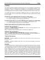
1 Safety
This manual contains information and warnings that must be followed for operating the
instrument safely and maintaining the instrument in a safe operating condition. If the
instrument is used in a manner not specified by the manufacturer, the protection
provided by the instrument may be impaired. The meter is intended only for indoor use.
The meter (all versions) is protected, against the users, by double insulation per
UL3111-1(1994), CSA C22.2 No. 1010-1-92, EN61010-1(1995) and IEC61010-1(1995)
to CAT III 600V.
Standard CE version MD 9030 series Terminals (to COM) ratings:
• V : Category II 1000 Volts AC & DC, and Category III 600 Volts AC & DC.
• A / mAμA : Category II 250 Volts ac and 150 Volts dc.
Protection-reinforced CE + UL version MD 9030 series Terminals (to COM) ratings:
• V : Category II 1000 Volts AC & DC, and Category III 600 Volts AC & DC.
• A / mAμA :Category III 500 Volts AC and 300 Volts dc.
PER IEC61010 OVERVOLTAGE INSTALLATION CATEGORY
OVERVOLTAGE CATEGORY II
Equipment of OVERVOLTAGE CATEGORY II is energy-consuming equipment to be
supplied from the fixed installation.
Note – Examples include household, office, and laboratory appliances.
OVERVOLTAGE CATEGORY III
Equipment of OVERVOLTAGE CATEGORY III is equipment in fixed installations.
Note – Examples include switches in the fixed installation and some equipment for
industrial use with permanent connection to the fixed installation.
TERMS IN THIS MANUAL
WARNING identifies conditions and actions that could result in serious injury or even
death to the user.
CAUTION identifies conditions and actions that could cause damage or malfunction
in the instrument.
WARNING
To reduce the risk of fire or electric shock, do not expose this product to rain or moisture.
To avoid electrical shock hazard, observe the proper safety precautions when working
with voltages above 60 VDC or 30 VAC rms. These voltage levels pose a potential
shock hazard to the user. Do not touch test lead tips or the circuit being tested while
power is applied to the circuit being measured. Keep your fingers behind the finger
guards of the test leads during measurement. Inspect test leads, connectors, and
probes for damaged insulation or exposed metal before using the instrument. If any
defects are found, replace them immediately. Do not measure any circuit that draws
more than the current rating of the protection fuse. Do not attempt a current
measurement where the open circuit voltage is above the protection fuse voltage rating.

MD 9030 TRMS Electrical & Electronic DMM with Temperature Cenelec Directives
5
Suspected open circuit voltage can be checked with voltage functions. Never attempt a
voltage measurement with the test lead inserted into the μA/mA or A input jack. Only
replace the blown fuse with the proper rating as specified in this manual.
CAUTION
Disconnect the test leads from the test points before changing functions. Always set the
instrument to the highest range and work downward for an unknown value when using
manual ranging mode.
INTERNATIONAL ELECTRICAL SYMBOLS
! Caution ! Refer to the explanation in this Manual
Caution ! Risk of electric shock
Earth (Ground)
Double Insulation or Reinforced insulation
Fuse
AC--Alternating Current
DC--Direct Current
2 Cenelec Directives
The instruments conform to CENELEC Low-voltage directive 73/23/EEC and
Electromagnetic compatibility directive 89/336/EEC

MD 9030 TRMS Electrical & Electronic DMM with Temperature Product Description
6
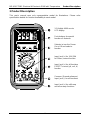
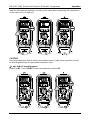
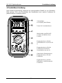
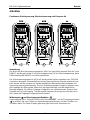
3 Product Description
This user's manual uses only representative model for illustrations. Please refer
specification details for function availability to each model.
3-3/4 digits 4000 counts
LCD display
Push-buttons for special
functions & features
Selector to turn the Power
On or Off and select a
function
Input Jack (+) for 10A (20A
for 30sec) current function
Input Jack (+) for all functions
EXCEPT current (
μ
A, mA, A)
function
Common (Ground reference)
Input Jack (-) for all functions
Input Jack (+) for milli-amp
and micro-amp functions

MD 9030 TRMS Electrical & Electronic DMM with Temperature Operation
7
4 Operation
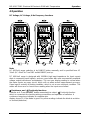
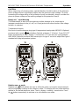
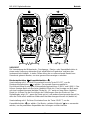
DC Voltage, AC Voltage, & Hz Frequency functions
Note:
AC 400.0mV range selection is by RANGE button manually, and is specified from AC
10mV (AC 40mV for True RMS model BM807) and up.
DC 400.0mV range is designed with 1000MΩ high input impedance for least current
drain in measuring small signals, and can cope better with most commercially available
voltage output transducers and adapters. The non-zero display reading is normal when
the meter inputs are open circuit, which will not affect actual measurement accuracy.
Open input is actually a floating condition, which is not a zero-volt-input condition. The
meter will show zero or close to zero reading when the inputs are shorted.
Ω Resistance, and Continuity functions
Defaults at Ω. Press SELECT button momentarily to select Continuity function
which is convenient for checking wiring connections and operation of switches. A
continuous beep tone indicates a complete wire.
display shows OL if the diode is good. Any other readings indicate the diode is resistive
or shorted (defective).

MD 9030 TRMS Electrical & Electronic DMM with Temperature Operation
8
CAUTION
Using Resistance, Continuity, Diode or Capacitance function in a live circuit will produce
false results and may damage the instrument. In many cases the suspected component
must be disconnected from the circuit to obtain an accurate measurement reading.
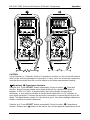
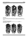
Diode test, Capacitance functions
Defaults at Ω. Press SELECT button momentarily 2 times to select Diode test
function. Normal forward voltage drop (forward biased) for a good silicon diode is
between 0.400V to 0.900V. A reading higher than that indicates a leaky diode
(defective). A zero reading indicates a shorted diode (defective). An OL indicates an
open diode (defective). Reverse the test leads connections (reverse biased) across the
diode. The digital display shows OL if the diode is good. Any other readings indicate the
diode is resistive or shorted (defective).
Defaults at Ω. Press SELECT button momentarily 3 times to select Capacitance
function. Relative zero mode can be used to zero out the parasitic capacitance of the

MD 9030 TRMS Electrical & Electronic DMM with Temperature Operation
9
leads and the internal protection circuitry of the meter when measuring low capacitance
in the order of Pico Farad (pF).
CAUTION
Discharge capacitors before making any measurement. Large value capacitors should
be discharged through an appropriate resistance load
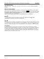
μA, mA, and A Current functions
Default at DC. Press SELECT button momentarily to select AC.

MD 9030 TRMS Electrical & Electronic DMM with Temperature Operation
10
CAUTION
When measuring a 3-phase system, special attention should be taken to the phase-to-
phase voltage which is significantly higher than the phase-to-earth voltage. To avoid
exceeding the voltage rating of the protection fuse(s) accidentally, always consider the
phase-to-phase voltage as the working voltage for the protection fuse(s).
Beep-Jack™ Input Warning
The meter beeps to warn the user against possible damage to the meter due to
improper connections to the μA, mA, or A input jacks when other function (like voltage
function) is selected.
Temperature function
Be sure to insert the banana plug type-K temperature bead probe AMD9023 (Optional
purchase) with correct polarities. Defaults at degree C (Celsius). Press SELECT
button momentarily to select degree F (Fahrenheit). You can also use a plug adapter
AMD 9024 (Optional purchase) with banana pins to type-K socket to adapt other type-K
standard mini plug temperature probes.
Relative zero mode
Relative zero mode allows the user to offset the meter consecutive measurements
with the displaying reading as the reference value. The display will now show readings
relative to the stored reference value. That is, display = reading - stored value. Press
the button momentarily to activate or to exit relative zero mode.

MD 9030 TRMS Electrical & Electronic DMM with Temperature Operation
11
Backlighted display
Press the SELECT button for 1 second or more to turn on or off the display backlight
function.
Manual or Auto-ranging
Press the RANGE button momentarily to select manual-ranging mode, and the meter
will remain in the range it was in, the LCD annunciator turns off. Press the button
momentarily again to step through the ranges. Press and hold the button for 1 second
or more to resume auto-ranging mode.
Note: Manual ranging mode feature is not available in Hz & Cx functions.
HOLD
The hold feature freezes the display for later view. Press the HOLD button
momentarily to activate or to exit the hold feature.
MAX
The max feature compares and displays the measured maximum value as fast as 25ms
in a single range, and with automatic up range capability. Press the MAX button for 1
second or more to activate or to exit the max feature in the voltage or current functions.
Sleep Mode
The meter will enter a low power consumption sleep mode automatically to extend
battery life after approximately 30 minutes of no rotary-switch or push button operations.
To wake up the meter from sleep mode, press any buttons momentarily or turn the
rotary-switch to an adjacent position. Always set the rotary-switch to the OFF position
manually when the meter is not in use.

MD 9030 TRMS Electrical & Electronic DMM with Temperature Maintenance
12
5 Maintenance
WARNING
To avoid electrical shock, disconnect the meter from any circuit, remove the test leads
from the input jacks and turn OFF the meter before opening the case. Do not operate
with open case.
Cleaning and Storage
Periodically wipe the case with a damp cloth and mild detergent; do not use abrasives
or solvents. If the meter is not to be used for periods of longer than 60 days, remove the
batteries and store them separately
Trouble Shooting
If the instrument fails to operate, check batteries and test leads etc., and replace as
necessary. Double check operating procedure as described in this user’s manual.
If the instrument voltage-resistance input terminal has subjected to high voltage
transient (caused by lightning or switching surge to the system) by accident or abnormal
conditions of operation, the series fusible resistors will be blown off (become high
impedance) like fuses to protect the user and the instrument. Most measuring functions
through this terminal will then be open circuit. The series fusible resistors and the spark
gaps should then be replaced by qualified technician. Refer to the LIMITED
WARRANTY section for obtaining warranty or repairing service.
Battery and Fuse replacement
Battery use:
Standard 1.5V AAA Size (NEDA 24A or IEC LR03) battery X 2
Standard CE Version MD 9030 series fuses:
Fuse (FS1) for μAmA current input: 0.5A/250V, F fuse;
Fuse (FS2) for A current input: 15A/250V, F fuse
Protection-reinforced CE + UL Version MD 9030 series fuses:
Fuse (FS1) for μAmA current input: 0.63A/500V, IR 200kA, F fuse;
Fuse (FS2) for A current input: 12.5A/500V, IR 20kA, F fuse
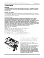
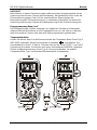
Battery replacement for models with battery
access door:
Loosen the 2 screws from the battery access
door of the case bottom. Lift the battery access
door and thus the battery compartment up.
Replace the battery. Re-fasten the screws.
Fuse replacement (and also Battery
replacement for splash proof version without
battery access door):
Loosen the 4 screws from the case bottom. Lift
the end of the case bottom nearest the input
jacks until it unsnaps from the case top.
Replace the blown fuse(s) and/or the battery.
Replace the case bottom, and ensure that all
the gaskets are properly seated and the two
snaps on the case top (near the LCD side) are
engaged. Re-fasten the screws..

MD 9030 TRMS Electrical & Electronic DMM with Temperature Specification
13
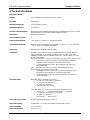
6 Specification
General Specifications
Display: 3-3/4 digits 4000 counts LCD display
Polarity: Automatic
Update Rate: 3 per second nominal
Operating Temperature: 0°C to 40°C
Relative Humidity: Maximum relative humidity 80% for temperature up to 31°C decreasing
linearly to 50% relative humidity at 40°C
Altitude: Operating below 2000m
Pollution degree: 2
Storage Temperature: -20OC to 60OC, < 80% R.H. (with battery removed)
Temperature Coefficient: nominal 0.15 x (specified accuracy)/OC @(0OC -18OC or 28OC -40OC), or
otherwise specified
Sensing: True RMS for MD 9030
Safety: The meter (all versions) is protected, against the users, by double
insulation per UL3111-1(1994), CSA C22.2 No. 1010-1-92, EN61010-
1(1995) and IEC61010-1(1995) to CAT II 1000V & CAT III 600V.
Standard CE version MD 9030 series Terminals (to COM) ratings:
• V :Category II 1000 Volts AC & DC, and Category III 600 Volts AC & DC.
• A / mAμA :Category II 250 Volts ac and 150 Volts dc.
Protection-reinforced CE + UL version series Terminals (to COM) ratings:
• V :Category II 1000 Volts AC & DC, and Category III 600 Volts AC & DC.
• A / mAμA :Category III 500 Volts AC and 300 Volts DC.
Overload Protections :
Standard CE MD9030 version series:
• μA & mA : 0.5A/250V F Fuse;
• A : 15A/250V F Fuse;
• V : 1050Vrms, 1450Vpeak;
Ω, & Others: 600VDC/VAC rms
Protection-reinforced CE + UL version MD9030 series:
• μA & mA : 0.63A/500V, IR200kA, F Fuse;
• A : 12.5A/500V, IR20kA, F Fuse;
• V : 1050Vrms, 1450Vpeak;
Ω, & Others: 600VDC/VAC rms
Transient protection: 6.5kV (1.2/50μs surge)
Power Supply: 1.5V AAA Size (NEDA 24A or IEC LR03) battery X 2
Power Consumption: 3.2 mA typical

MD 9030 TRMS Electrical & Electronic DMM with Temperature Specification
14
Low Battery: Below approx. 2.4V
E.M.C.: Meets EN61326(1997, 1998/A1), EN61000-4-2(1995), and EN61000-4-3(1996)
In an RF field of 3V/m:
• Capacitance function is not specified
• AC 4.000V range: Total Accuracy = Specified Accuracy + 700 digits
• AC 400.0μA range: Total Accuracy = Specified Accuracy + 300 digits
• Other function ranges: Total Accuracy = Specified Accuracy + 40 digits
• Performance above 3V/m is not specified
Sleep Mode Timing: Idle for 30 minutes
Sleep Mode Consumption: 360μA typical for MD 9030
Dimension: L186mm X W87mm X H35.5mm; L198mm X W97mm X H55mm with holster
Weight: 296 gm; 396 gm with holster
Special Features: 25ms Max Hold; Data Hold; Relative zero mode; Beep-jack™ input warning;
Back-lighted display
Accessories: Test leads (pair), batteries installed, user's manual
Optional Accessories: Banana plug type-K bead probe AMD9023 x 1 (Banana pins to type-K socket
plug adapter AMD9024
Electrical Specifications
Accuracy is ±(% reading digits + number of digits) or otherwise specified, at 23 OC ±5 OC & less than 75%
R.H. Model MD 9030 True RMS accuracy of ACV & ACA is specified from 5 % (10% for AC400.0mV
range) to 100 % of range, or otherwise specified. Maximum Crest Factor < 1.75 : 1 at full scale & < 3.5 : 1
at half scale, and with frequency components within the specified frequency bandwidth for non-sinusoidal
waveforms
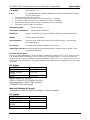
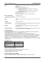
DC Voltage
RANGE Accuracy
400.0 MV 0.3% + 4D
4.000V, 40.00V,
400.0V 0.5% + 3D
1000V 1.0% + 4D
NMRR:>50dB @ 50/60Hz
CMRR:>120dB @ DC, 50/60Hz, Rs=1kΩ
Input impedance : 10MΩ, 30pF nominal
(1000MΩ for 400.0mV range)
Max Hold (Voltage & Current)
Specified accuracy ± 50 digits for changes > 25ms in duration
AC Voltage
RANGE Accuracy
50HZ -- 500HZ
400.0mV* 4.0% + 5d
4.000V, 40.00V,
400.0V 1.5% + 5d
1000V 4.0% + 5d

MD 9030 TRMS Electrical & Electronic DMM with Temperature Specification
15
CMRR:>60dB @ DC TO 60Hz, RS=1kΩ
Input Impedance: 10MΩ, 30pF nominal
(1000MΩ for 400.0mV range)
*Selection by RANGE button manually, and is specified from AC 10mV (AC 40mV for
True RMS model MD 9030) and up
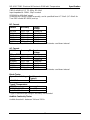
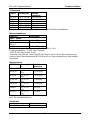
DC Current
RANGE Accuracy Burden
Voltage
400.0μA 2.0% + 5d 0.15mV/μA
4000μA 1.2% + 3d 0.15mV/μA
40.00mA 2.0% + 5d 3.3mV/mA
400.0mA 1.2% + 3d 3.3mV/mA
4.000A 2.0% + 5d 0.03V/A
10.00A* 1.2% + 3d 0.03V/A
*10A continuous, 20A for 30 second max with 5 minutes cool down interval
AC Current
RANGE Accuracy
1) Burden
Voltage
50Hz -- 500Hz
400.0μA 2.0% + 6d 0.15mV/μA
4000μA 1.5% + 4d 0.15mV/μA
40.00mA 2.0% + 6d 3.3mV/mA
400.0mA 1.7% + 4d 3.3mV/mA
4.000A 2.0% + 6d 0.03V/A
10.00A* 1.8% + 4d 0.03V/A
*10A continuous, 20A for 30 second max with 5 minutes cool down interval
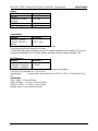
Diode Tester
Open Circuit Voltage Test Current
(Typical)
< 1.6 VDC 0.25mA
Type-K Temperature
RANGE Accuracy*
-20 OC TO 300 OC 2% + 3 OC
-4 OF TO 572 OF 2% + 6 OF
*Type-K thermocouple range & accuracy not included
Audible Continuity Tester
Audible threshold : between 10Ω and 120Ω

MD 9030 TRMS Electrical & Electronic DMM with Temperature Specification
16
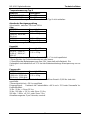
Ohms
RANGE Accuracy
400.0Ω 0.8% + 6d
4.000kΩ, 40.00kΩ,
400.0kΩ 0.6% + 4d
4.000MΩ 1.0% + 4d
40.00MΩ 2.0% + 4d
Open Circuit Voltage : 0.4VDC typical
Capacitance
RANGE* Accuracy**
500.0nF, 5.000μF,
50.00μF, 500.0μF,
3000μF
3.5%*** + 6d
*Additional 50.00nF range accuracy is not specified
**Accuracies with film capacitor or better
***Specified with battery voltage above 2.8V (approximately half full battery). Accuracy
decreases gradually to 12% at low battery warning voltage of approximately 2.4V
Hz Frequency
RANGE* Accuracy**
50.00Hz, 500.0Hz,
5.000kHz, 50.00kHz,
500.0kHz, 1.000MHz
0.5%+4d
*Additional 5.000Hz range accuracy & sensitivity are not specified
**Accuracy is specified at < 20VAC rms
Input Signal : Square wave with duty cycle > 40% & < 70%; or Sine wave Vrms
AC
Sensitivity :
10Hz--20Hz : > Sine 0.9Vrms;
20Hz--500kHz : > 2.6Vp; or Sine 1.9Vrms;
500kHz--1MHz : > 4.2Vp; or Sine 3Vrms
Update Rate : 2 per second nominal

MD 9030 TRMS Electrical & Electronic DMM with Temperature Limited Warranty
17
LIMITED WARRANTY
METREL warrants to the original product purchaser that each product it manufactures
will be free from defects in material and workmanship under normal use and service
within a period of three years from the date of purchase. METREL's warranty does not
apply to accessories, fuses, fusible resistors, spark gaps, batteries or any product
which, in METREL's opinion, has been misused, altered, neglected, or damaged by
accident or abnormal conditions of operation or handling.
To obtain warranty service, contact your supplier or send the product, with proof of
purchase and description of the difficulty, postage and insurance prepaid, to METREL
UK, Unit 1, Hopton House, Ripley Drive, Normanton, West Yorkshire, WF6 1QT.
METREL assumes no risk for damage in transit. METREL will, at its option, repair or
replace the defective product free of charge. However, if METREL determines that the
failure was caused by misused, altered, neglected, or damaged by accident or abnormal
conditions of operation or handling, you will be billed for the repair. The cost of logistics
shall be carried by the owner of the product.
THIS WARRANTY IS EXCLUSIVE AND IS IN LIEU OF ALL OTHER WARRANTIES,
EXPRESSED OR IMPLIED, INCLUDING BUT NOT LIMITED TO ANY IMPLIED
WARRANTY OR MERCHANTABILITY OR FITNESS FOR A PARTICULAR PURPOSE
OR USE. METREL WILL NOT BE LIABLE FOR ANY SPECIAL, INDIRECT,
INCIDENTAL OR CONSEQUENTIAL DAMAGES.
PRINTED ON RECYCLABLE PAPER, PLEASE RECYCLE

MD 9030 Digitalmultimeter Sicherheit
18
1 Sicherheit
Diese Anleitung enthält Informationen und Warnungen, die befolgt werden müssen, um
das Instrument sicher zu betreiben und in sicherem Betriebszustand zu erhalten. Wenn
das Gerät auf eine Weise benutzt wird, die nicht vom Hersteller angegeben wurde, kann
der Schutz, den das Gerät bietet, beeinträchtigt werden. Das Messgerät ist nur für den
Gebrauch in Innenräumen bestimmt.
Das Messgerät (alle Versionen) ist gegenüber den Anwendern durch Schutzisolierung
nach UL3111-1(1994), CSA C22.2 No. 1010-1-92, EN61010-1(1995) und IEC61010-
1(1995) nach CAT II 1000 V und CAT III 600 V geschützt.
Serie MD9030, Standard-CE-Version, Nennwerte der Anschlüsse (nach COM):
V: Kategorie II 1000 V Wechsel- und Gleichspannung sowie Kategorie III 600 V
Wechsel- und Gleichspannung
A / mAμA: Kategorie II 250 V Wechselspannung und 150 V Gleichspannung
Serie MD9030, CE- und UL-Version* mit verstärktem Schutz, Nennwerte der
Anschlüsse (nach COM):
V: Kategorie II 1000 V Wechsel- und Gleichspannung sowie Kategorie III 600 V
Wechsel- und Gleichspannung
A / mAμA: Kategorie III 500 V Wechselspannung und 300 V Gleichspannung
ÜBERSPANNUNGS-INSTALLATIONSKATEGORIE NACH IEC61010
ÜBERSPANNUNGSKATEGORIE II
Eine Einrichtung der ÜBERSPANNUNGSKATEGORIE II ist eine energieverbrauchende
Einrichtung, die von der festen Anlage versorgt werden muss.
Anmerkung – Beispiele sind Haushalts-, Büro- und Laborgeräte.
ÜBERSPANNUNGSKATEGORIE III
Eine Einrichtung der ÜBERSPANNUNGSKATEGORIE III ist eine Einrichtung in festen
Anlagen.
Anmerkung – Beispiele sind Schalter in der festen Anlage und einige Einrichtungen für
den industriellen Gebrauch mit dauernder Verbindung zur festen Anlage.
Begriffe in dieser Anleitung:
WARNUNG Gibt Bedingungen oder Aktionen an, die zu schweren Verletzungen oder
sogar zum Tod des Anwenders führen könnten.
VORSICHT Gibt Bedingungen oder Aktionen an, die Beschädigungen oder
Fehlfunktionen des Instruments verursachen könnten.
Begriffe in dieser anleitung
WARNUNG Gibt Bedingungen oder Aktionen an, die zu schweren Verletzungen oder
sogar zum Tod des Anwenders führen könnten.
VORSICHT Gibt Bedingungen oder Aktionen an, die Beschädigungen oder
Fehlfunktionen des Instruments verursachen könnten.

MD 9030 Digitalmultimeter Cenelec-Richtlinien
19
WARNUNG
Um die Brand- oder Stromschlaggefahr zu reduzieren, setzen Sie dieses Produkt nicht
Regen oder Feuchtigkeit aus. Um Stromschlaggefahr zu vermeiden, beachten Sie die
geeigneten Sicherheitsmaßnahmen bei Arbeiten an Spannungen über 60 VDC oder 30
Veff. Diese Spannungspegel stellen eine mögliche Stromschlaggefahr für den Anwender
dar. Berühren Sie die Messspitzen oder den zu prüfenden Kreis nicht, während er unter
Spannung steht. Halten Sie Ihre Finger bei der Messung hinter den
Fingerschutzschilden an den Prüfleitungen. Untersuchen Sie vor der Verwendung des
Instruments die Prüfleitungen, Steckverbinder und Sonden auf beschädigte Isolierung
oder frei liegendes Metall. Wenn Sie Defekte finden, wechseln Sie die Teile sofort aus.
Messen Sie keinen Strom, der den Nennstrom der Schutzsicherung übersteigt.
Versuchen Sie keine Strommessung an einem Kreis, dessen Leerlaufspannung über
der Nennspannung der Schutzsicherung liegt. Die vermutete Leerlaufspannung sollte
mit den Spannungsfunktionen überprüft werden. Versuchen Sie niemals eine
Spannungsmessung, wenn die Prüfleitung in der μA/mA- oder A-Eingangsbuchse
steckt. Ersetzen Sie eine durchgebrannte Sicherung nur durch eine mit den richtigen
Nennwerten, wie sie in dieser Anleitung angegeben sind.
VORSICHT
Trennen Sie vor dem Umschalten von Funktionen die Prüfleitungen von den
Prüfpunkten. Stellen Sie das Instrument immer auf den höchsten Bereich und arbeiten
Sie sich nach unten, wenn Sie bei einem unbekannten Wert die manuelle Bereichswahl
verwenden.
INTERNATIONALE ELEKTROSYMBOLE
! Vorsicht! Siehe Erklärungen in dieser Anleitung
Vorsicht! Es besteht die Gefahr eines Stromschlags!
Erde (Erdung)
Doppelisolierung oder Schutzisolierung
Sicherung
AC--Wechselstrom
DC—Gleichstrom
2 Cenelec-Richtlinien
Die Instrumente entsprechen der CENELEC-Niederspannungsrichtlinie 73/23/EWG und
der Richtlinie „Elektromagnetische Verträglichkeit“ 89/336/EWG.

MD 9030 Digitalmultimeter Produktbeschreibung
20
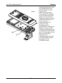
3 Produktbeschreibung
Diese Bedienungsanleitung verwendet ein repräsentatives Modell nur zur Illustration.
Bitte schauen Sie in den Einzelheiten der Spezifikation nach, welche Funktionen für
jedes Modell zur Verfügung stehen.
3-3/4-stelliges
LCD-Display (4000 Zähler)
Tasten für Sonderfunktionen
Wahlschalter zum EIN-/AUS-
Schalten und Wählen einer
Funktion
Eingangsbuchse (+) für die
Stromfunktion 10 A (20 A für 30
s)
Eingangsbuchse (+) für alle
Funktionen AUSSER der
Stromfunktion (μA, mA, A)
Gemeinsame (Bezugsmasse-)
Eingangsbuchse (-) für alle
Funktionen
Eingangsbuchse (+) für die
Milliampere- und Mikroampere-
Funktionen
Seite wird geladen ...
Seite wird geladen ...
Seite wird geladen ...
Seite wird geladen ...
Seite wird geladen ...
Seite wird geladen ...
Seite wird geladen ...
Seite wird geladen ...
Seite wird geladen ...
Seite wird geladen ...
Seite wird geladen ...
Seite wird geladen ...
-
 1
1
-
 2
2
-
 3
3
-
 4
4
-
 5
5
-
 6
6
-
 7
7
-
 8
8
-
 9
9
-
 10
10
-
 11
11
-
 12
12
-
 13
13
-
 14
14
-
 15
15
-
 16
16
-
 17
17
-
 18
18
-
 19
19
-
 20
20
-
 21
21
-
 22
22
-
 23
23
-
 24
24
-
 25
25
-
 26
26
-
 27
27
-
 28
28
-
 29
29
-
 30
30
-
 31
31
-
 32
32


METREL MD 9030 Benutzerhandbuch
- Kategorie
- Messen, Testen
- Typ
- Benutzerhandbuch
in anderen Sprachen
- English: METREL MD 9030 User manual
Verwandte Artikel
-
METREL EDMD9030 Benutzerhandbuch
-
 METREL MD 9050 Benutzerhandbuch
-
 METREL EDMD9015 Bedienungsanleitung
-
 METREL MD 1155 Benutzerhandbuch
-
 METREL MD 9050 Benutzerhandbuch
-
 METREL MD 9020 Benutzerhandbuch
-
 METREL MD 9225 Industrial TRMS AC-DC Current Clamp Meter Benutzerhandbuch
-
 METREL MD 9225 Benutzerhandbuch
-
 METREL MD 9016 Benutzerhandbuch
-
 METREL MD 9880 Benutzerhandbuch


