EUCHNER Safety Switch NZ.H/P Bedienungsanleitung
- Typ
- Bedienungsanleitung

1
Betriebsanleitung
Sicherheitsschalter NZ.H/P
Gültigkeit
Diese Betriebsanleitung gilt für alle NZ.H/P. Diese
Betriebsanleitung bildet zusammen mit dem Do-
kument Sicherheitsinformation und Wartung sowie
einem ggf. beiliegenden Datenblatt die vollständige
Benutzerinformation für Ihr Gerät.
Ergänzende Dokumente
Die Gesamtdokumentation für dieses Gerät besteht
aus folgenden Dokumenten:
Dokumenttitel
(Dokumentnummer) Inhalt
Sicherheitsinformation
(2525460)
Grundlegende Sicherheitsinforma-
tionen
Betriebsanleitung
(2074550)
(dieses Dokument)
Internet
www
Konformitätserklärung Konformitätserklärung
Internet
www
Ggf. Ergänzungen zur
Betriebsanleitung
Ggf. zugehörige Ergänzungen zur
Betriebsanleitung oder Datenblätter
berücksichtigen.
Internet
www
Wichtig!
Lesen Sie immer alle Dokumente durch, um einen
vollständigen Überblick für die sichere Installati-
on, Inbetriebnahme und Bedienung des Geräts
zu bekommen. Die Dokumente können unter
www.euchner.de heruntergeladen werden. Geben
Sie hierzu die Dok. Nr. oder die Bestellnummer des
Geräts in die Suche ein.
Bestimmungsgemäßer Gebrauch
Sicherheitsschalter der Baureihe NZ sind Verriege-
lungseinrichtungen ohne Zuhaltung (Bauart1). Der Be-
tätiger ist uncodiert (z.B. Nocken). In Verbindung mit
einer beweglichen trennenden Schutzeinrichtung und
der Maschinensteuerung verhindert dieses Sicher-
heitsbauteil, dass gefährliche Maschinenfunktionen
ausgeführt werden, solange die Schutzeinrichtung
geöffnet ist. Wenn die Schutzeinrichtung während
der gefährlichen Maschinenfunktion geöffnet wird,
wird ein Stoppbefehl ausgelöst.
Das bedeutet:
fEinschaltbefehle, die eine gefährliche Maschinen-
funktion hervorrufen, dürfen erst dann wirksam wer-
den, wenn die Schutzeinrichtung geschlossen ist.
fDas Öffnen der Schutzeinrichtung löst einen Stopp-
befehl aus.
fDas Schließen einer Schutzeinrichtung darf kein
selbstständiges Anlaufen einer gefährlichen Maschi-
nenfunktion hervorrufen. Hierzu muss ein separater
Startbefehl erfolgen. Ausnahmen hierzu siehe
ENISO12100 oder relevante C-Normen
Geräte dieser Baureihe können als sichere Positions-
geber eingesetzt werden.
Vor dem Einsatz des Geräts ist eine Risikobeurteilung
an der Maschine durchzuführen z.B. nach folgenden
Normen:
fENISO13849-1
fENISO12100
fIEC62061
Zum bestimmungsgemäßen Gebrauch gehört das
Einhalten der einschlägigen Anforderungen für den
Einbau und Betrieb, insbesondere nach folgenden
Normen:
fENISO13849-1
fENISO14119
fEN60204-1
Wichtig!
fDer Anwender trägt die Verantwortung für die
korrekte Einbindung des Geräts in ein sicheres
Gesamtsystem. Dazu muss das Gesamtsystem
z.B. nach ENISO13849-2 validiert werden.
fWird zur Bestimmung des Perfomance Le-
vels (PL) das vereinfachte Verfahren nach
ENISO 13849-1:2015, Abschnitt 6.3 benutzt,
reduziert sich möglicherweise der PL, wenn
mehrere Geräte hintereinander geschaltet werden.
fEine logische Reihenschaltung sicherer Kontakte
ist unter Umständen bis zu PLd möglich. Nähere
Informationen hierzu gibt ISOTR24119.
fLiegt dem Produkt ein Datenblatt bei, gelten die
Angaben des Datenblatts, falls diese von der
Betriebsanleitung abweichen.
Sicherheitshinweise
WARNUNG
Lebensgefahr durch unsachgemäßen Einbau oder
Umgehen (Manipulation). Sicherheitsbauteile erfüllen
eine Personenschutzfunktion.
fSicherheitsbauteile dürfen nicht überbrückt,
weggedreht, entfernt oder auf andere Weise
unwirksam gemacht werden. Beachten Sie
hierzu insbesondere die Maßnahmen zur Ver-
ringerung der Umgehungsmöglichkeiten nach
ENISO14119:2013, Abschn. 7.
fMontage, elektrischer Anschluss und Inbetriebnah-
me ausschließlich durch autorisiertes Fachperso-
nal, welches über spezielle Kenntnisse im Umgang
mit Sicherheitsbauteilen verfügt.
Funktion
Die Geräte werden zum Positionieren und Steuern im
Maschinen- und Anlagenbau eingesetzt.
Das Schaltelement wird über einen Schwenkhebel
betätigt. Die Sicherheitskontakte werden dabei
zwangsweise geöffnet (siehe Bild 5).
Schaltzustände
Die detaillierten Schaltzustände für Ihren Schalter
nden Sie in Bild 5. Dort sind alle verfügbaren Schal-
telemente beschrieben.
Montage
HINWEIS
Geräteschäden durch falschen Anbau und ungeeig-
nete Umgebungsbedingungen
fSicherheitsschalter und Betätiger dürfen nicht als
Anschlag verwendet werden.
fBeachten Sie ENISO14119:2013, Abschnitte 5.2
und 5.3, zur Befestigung des Sicherheitsschalters
und des Betätigers.
fBeachten Sie ENISO14119:2013, Abschnitt 7,
zur Verringerung von Umgehungsmöglichkeiten
einer Verriegelungseinrichtung
fSchützen Sie den Schalterkopf vor Beschädigung.
fDer Betätiger (Schwenkhebel) muss formschlüs-
sig auf der Antriebswelle befestigt werden. Die
Vielkante an Betätiger und Antriebswelle müssen
ineinander greifen (siehe Bild 2).
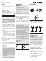
fUm den ordnungsgemäßen Betrieb sicherzustel-
len, müssen die Steuernocken so angebracht
sein, dass die Betätiger mindestens bis zu einem
Winkel von
45° +5°
ausgelenkt werden (Erreichen
der vorgeschriebenen Kontaktöffnung, siehe Bild
8 und Bild 9).
fDie angegebene IP-Schutzart gilt nur, bei korrekt
angezogenen Gehäuseschrauben, Leitungsein-
führungen und Steckverbindern. Anzugsdrehmo-
mente beachten.
Wichtig!
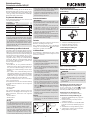
fUm ein Prellen des Betätigungselements zu ver-
hindern muss der Nocken allmählich auslaufen
(siehe Bild 1).
α
αα
Bild 1: Nockenform
Umstellmöglichkeiten
Vertikale Umsetzbarkeit Betätiger 8x45°
(formschlüssig)
45°
90°
Beispiel:
Bild 2: Vertikale Umsetzbarkeit Betätiger
Horizontale Umsetzbarkeit 4 x 90°
Bild 3: Horizontale Umsetzbarkeit
1. Schrauben am Betätigungskopf lösen.
2. Gewünschte Richtung einstellen.
3. Schrauben mit 1,2 Nm anziehen.
Schaltrichtungsumstellung bei
Schwenkhebelantrieb
Links / rechts Rechts Links
schaltend schaltend schaltend
(Standardeinstellung)
Bild 4: Schaltrichtungsumstellung
Elektrischer Anschluss
WARNUNG
Verlust der Sicherheitsfunktion durch falschen
Anschluss.
fFür Sicherheitsfunktionen nur sichere Kontakte (
) verwenden.
fIsolieren Sie die Einzeldrähte mit einer Länge
von 6±1mm ab, um einen sicheren Kontakt zu
gewährleisten.
Anwendung des Sicherheitsschalters als
Verriegelung für den Personenschutz
Es muss mindestens ein Kontakt verwendet
werden. Dieser signalisiert die Stellung der Schutz-
einrichtung (Kontaktbelegung siehe Bild 7).
Für Geräte mit Steckverbinder gilt:
fAuf Dichtheit des Steckverbinders achten.
Für Geräte mit Leitungseinführung gilt:
1. Gewünschte Einführöffnung mit geeignetem
Werkzeug öffnen.
2. Kabelverschraubung mit entsprechender
Schutzart montieren.
3. Anschließen und Klemmen mit 0,5Nm (1 Nm
bei ES511) anziehen (Kontaktbelegung siehe
Bild 7).
4. Auf Dichtheit der Leitungseinführung achten.
5. Schalterdeckel schließen und verschrauben
(Anzugsdrehmoment 1,2Nm).

2
Betriebsanleitung
Sicherheitsschalter NZ.H/P
Funktionsprüfung
WARNUNG
Tödliche Verletzung durch Fehler bei der Funkti-
onsprüfung.
fStellen Sie vor der Funktionsprüfung sicher, dass
sich keine Personen im Gefahrenbereich benden.
fBeachten Sie die geltenden Vorschriften zur
Unfallverhütung.
Überprüfen Sie nach der Installation und nach jedem
Fehler die korrekte Funktion des Geräts.
Gehen Sie dabei folgendermaßen vor:
Mechanische Funktionsprüfung
Das Betätigungselement muss sich leicht bewegen
lassen. Zur Prüfung Schutzeinrichtung mehrmals
schließen.
Elektrische Funktionsprüfung
1. Betriebsspannung einschalten.
2. Alle Schutzeinrichtungen schließen.
¨ Die Maschine darf nicht selbständig anlaufen.
3. Maschinenfunktion starten.
4. Schutzeinrichtung öffnen.
¨ Die Maschine muss abschalten und darf sich nicht
starten lassen, solange die Schutzeinrichtung
geöffnet ist.
Wiederholen Sie die Schritte 2 - 4 für jede Schutz-
einrichtung einzeln.
Kontrolle und Wartung
WARNUNG
Gefahr von schweren Verletzungen durch den
Verlust der Sicherheitsfunktion.
fBei Beschädigung oder Verschleiß muss der
gesamte Schalter ausgetauscht werden. Der
Austausch von Einzelteilen oder Baugruppen ist
nicht zulässig.
fÜberprüfen Sie in regelmäßigen Abständen und
nach jedem Fehler die korrekte Funktion des Ge-
räts. Hinweise zu möglichen Zeitintervallen entneh-
men Sie der ENISO14119:2013, Abschnitt 8.2.
Um eine einwandfreie und dauerhafte Funktion zu
gewährleisten, sind folgende Kontrollen erforderlich:
feinwandfreie Schaltfunktion
fsichere Befestigung aller Bauteile
fBeschädigungen, starke Verschmutzung, Ablage-
rungen und Verschleiß
fDichtheit der Kabeleinführung
fgelockerte Leitungsanschlüsse bzw. Steckver-
binder.
Info: Das Baujahr ist in der unteren, rechten Ecke des
Typschilds ersichtlich.
Haftungsausschluss und
Gewährleistung
Wenn die o. g. Bedingungen für den bestimmungsge-
mäßen Gebrauch nicht eingehalten werden oder wenn
die Sicherheitshinweise nicht befolgt werden oder
wenn etwaige Wartungsarbeiten nicht wie gefordert
durchgeführt werden, führt dies zu einem Haftungs-
ausschluss und dem Verlust der Gewährleistung.
Hinweise zu
Für Geräte mit Leitungseinführung gilt:
Für den Einsatz und die Verwendung gemäß den
Anforderungen von ist eine Kupferleitung für
den Temperaturbereich 60/75°C zu verwenden.
Für Geräte mit Steckverbinder gilt:
Für den Einsatz und die Verwendung gemäß den
Anforderungen von muss eine Class 2 Span-
nungsversorgung nach UL1310 verwendet werden.
Am Einsatzort installierte Anschlussleitungen von Si-
cherheitsschaltern müssen räumlich von beweglichen
und fest installierten Leitungen und nicht isolierten
aktiven Teilen anderer Anlagenteile, die mit einer Span-
nung von über 150V arbeiten, so getrennt werden,
dass ein ständiger Abstand von 50,8 mm eingehalten
wird. Es sei denn, die beweglichen Leitungen sind
mit geeigneten Isoliermaterialien versehen, die eine
gleiche oder höhere Spannungsfestigkeit gegenüber
den anderen relevanten Anlagenteilen besitzen.
EU-Konformitätserklärung
Die Konformitätserklärung ist Bestandteil der Be-
triebsanleitung.
Die vollständige EU-Konformitätserklärung nden
Sie auch unter www.euchner.de. Geben Sie dazu die
Bestellnummer Ihres Geräts in die Suche ein. Unter
Downloads ist das Dokument verfügbar.
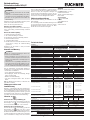
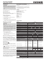
Technische Daten
Parameter Wert
Gehäusewerkstoff Leichtmetall-Druckguss anodisch oxidiert
NZ1... Leitungseinführung
NZ2... Steckverbinder M12/SVM5 NZ2... Steckverbinder SR6/SR11
Schutzart IP 67 IP 65
Mech. Schaltspiele 30 x 106
Umgebungstemperatur -25 ... +80 °C
Verschmutzungsgrad (extern, nach EN 60947-1) 3 (Industrie)
Einbaulage beliebig
Betätiger HB HS PB PS
Anfahrgeschwindigkeit max. 300 m/min 60 m/min 120 m/min 30 m/min
Anfahrgeschwindigkeit min. 0,1 m/min 0,1 m/min 0,5 m/min 0,5 m/min
Betätigungshäugkeit 10.000/h 7.000/h
Betätigungskraft bei 20 °C 15 N
Kontaktwerkstoff Silberlegierung hauchvergoldet
NZ1... NZ2...
Anschlussart Schraubanschluss Steckverbinder
Leiterquerschnitt (starr/exibel) 0,34 ... 1,5 mm²,
0,34 ... 0,75 mm² mit LED-Anzeige
SR6: 0,5 ... 1,5 mm²
SR11: 0,5 mm²
NZ1...M / NZ2...SR6 NZ2...SR11 NZ2...SVM5
Bemessungsisolationsspannung Ui = 250 V Ui = 50 V Ui = 50 V
Bemessungsstoßspannungsfestigkeit Uimp = 2,5 kV Uimp = 1,5 kV Uimp = 1,5 kV
Bedingter Kurzschlussstrom 100 A
Anzeigeleuchte LED L060 L110 L220
Nur mit Schaltelementen ES511, ES528H, ES538H AC/DC 12 - 60 V AC 110 V ±15% AC 230 V ±15%
Bemessungsdaten der Schaltelemente ES511 ES528H/ES538H SK2121H/SK2131H/
SK3131H
Schaltprinzip Sprungschalter Schleichschalter Schleichschalter
Gebrauchskategorie nach IEC 60947-5-1
mit Leitungseinführung AC-12 Ie 10 A Ue 230 V - -
AC-15 Ie 6 A Ue 230 V Ie 4 A Ue 230 V Ie 4 A Ue 230 V
DC-13 Ie 6 A Ue 24 V Ie 4 A Ue 24 V Ie 4 A Ue 24 V
mit Steckverbinder SR6 1) AC-15 Ie 6 A Ue 230 V Ie 4 A Ue 230 V -
DC-13 Ie 6 A Ue 24 V Ie 4 A Ue 24 V -
mit Steckverbinder SR11 1) AC-15 - - Ie 4 A Ue 50 V
DC-13 - - Ie 4 A Ue 24 V
mit Steckverbinder SVM5 AC-15 Ie 4 A Ue 30 V Ie 4 A Ue 30 V -
DC-13 Ie 4 A Ue 24 V Ie 4 A Ue 24 V -
Kurzschlussschutz (Steuersicherung) 1) siehe
Gebrauchskategorie
4 A gG 4 A gG
Konventioneller thermischer Strom Ith 1) 4 A 4 A
Schaltstrom min. bei 10 mA 1 mA 10 mA 1 mA 10 mA
Schaltspannung DC 24 V DC 24 V DC 12 V DC 24 V DC 12 V
1) Einschränkung für NZ2... bei Umgebungstemperatur > 70 ... 80 °C:
NZ2...SR6 NZ2...SR11
Gebrauchskategorie nach IEC 60947-5-1 AC-15 Ie 2 A Ue 230 V Ie 2 A Ue 50 V
DC-13 Ie 2 A Ue 24 V Ie 2 A Ue 24 V
Kurzschlussschutz (Steuersicherung) 2 A gG 2 A gG
Konventioneller thermischer Strom Ith 2 A 2 A
Zuverlässigkeitswerte nach ENISO13849-1 2)
in Abhängigkeit vom Schaltstrom bei 24VDC
bei DC-13 100mA/24V
≤0,1A
B10D
ES511 -
ES528H/ES538H 2 x 10⁷
SK2121H/SK2131H/SK3131H 2 x 10⁷
2) Ausgabedatum siehe EU-Konformitätserklärung
Service
Wenden Sie sich im Servicefall an:
EUCHNER GmbH + Co. KG
Kohlhammerstraße 16
70771 Leinfelden-Echterdingen
Deutschland
Servicetelefon:
+49 711 7597-500
E-Mail:
support@euchner.de
Internet:
www.euchner.de

Betriebsanleitung
Sicherheitsschalter NZ.H/P
3
Technische Änderungen vorbehalten, alle Angaben ohne Gewähr. © EUCHNER GmbH + Co. KG 2074550-15-03/23 (Originalbetriebsanleitung)
ES511 ES528H ES538H
SK2131H SK3131H
A
B
C
A
B
A
A
B
A
A
B
A
A
A
B
SK2121H
A
A
B
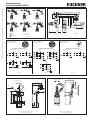
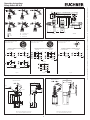
Bild 5: Schaltwegdiagramme
Kontakte
offen
geschlossen
A Schaltpunkt
B Endstellung
C Rückschaltpunkt
Bild 6: Maßzeichnung NZ2... mit Steckverbinder
SR11WFSR6WF
55 13,5
50
75
40
56
40 11
15,2
SR6EF/SR11EF
∅28
60
80
16
26
Steck-
verbinder Leitungsdurchmesser [mm]
SR6 7,0…9,0
SR11 8,0…10,0
gesteckt
gesteckt
gesteckt
Bild 7: Schaltelemente und Steckerbelegung
Steckverbinder SR6
Pinbelegung Stiftdose
(Ansicht auf Geräteseite)
Steckverbinder SR11
Pinbelegung Stiftdose
(Ansicht auf Geräteseite)
Steckverbinder SVM5
Pinbelegung Stiftdose
(Ansicht auf Geräteseite)
4
3
1
2
Kontaktbelegung Schaltelemente Kontaktbelegung Schaltelemente Kontaktbelegung Schaltelemente
3
1
4
2
13
21
14
22
56
3
1
4
2
13
21
14
22
3
1
4
2
11
21
12
22
56
3
1
4
2
11
21
12
22
ES 511/ES 528H ES 538H
mit LED-Anzeige
7
5
3
1
8
6
4
2
41
31
21
11
42
32
22
12
7
5
3
1
8
6
4
2
41
33
21
11
42
34
22
12
SK2121H SK2131H
3
1
4
2
13
21
14
22
56
3
1
4
2
13
21
14
22
3
1
4
2
11
21
12
22
56
3
1
4
2
11
21
12
22
ES 511/ES 528H ES 538H
7
5
3
1
8
6
4
2
41
33
21
13
42
34
22
14
SK3131H
Bild 3a Bild 3b Bild 3c
Bild 8: Maßzeichnung NZ1H.. mit Leitungseinführung
Anfahrrichtungen
HB = Kunststoffrolle (Maß X=6 mm)
HS = Stahlrolle (Maß X=5 mm)
3
0
m
a
x
.
4
5
+
5
40+1
30±0,1
74
100
22
7,3
60±0,1
5,3
5,3
X
64
56
32
18
42
16
32
M=1,8 Nm
M=1,2 Nm
M20x1,5
Nocken
PB = Kunststoffrolle (Maß X=6 mm)
PS = Stahlrolle (Maß X=5 mm)
Anfahrrichtungen
M = 1,8 Nm
66
59
X
M20x1,5
Bild 9: Maßzeichnung NZ1P.. mit Leitungseinführung

4
Operating Instructions
Safety Switch NZ.H/P
Scope
These operating instructions are valid for all NZ.H/P.
These operating instructions, the document Safety
information and maintenance and any enclosed
data sheet form the complete user information for
your device.
Supplementary documents
The overall documentation for this device consists
of the following documents:
Document title
(document number) Contents
Safety information
(2525460)
Basic safety information
Operating instructions
(2074550)
(this document)
Internet
www
Declaration of con-
formity Declaration of conformity
Internet
www
Any additions to the
operating instructions
Take any associated additions to
the operating instructions or data
sheets into account.
Internet
www
Important!
Always read all documents to gain a complete
overview of safe installation, setup and use of
the device. The documents can be downloaded
from www.euchner.com. For this purpose, enter
the doc. no. or the order number for the device
in the search box.
Correct use
Safety switches series NZ are interlocking devices
without guard locking (type1). The actuator is
uncoded (e.g. dog). In combination with a movable
guard and the machine control, this safety compo-
nent prevents dangerous machine functions from
occurring while the guard is open. A stop command
is triggered if the guard is opened during the dan-
gerous machine function.
This means:
fStarting commands that cause a dangerous ma-
chine function must become active only when the
guard is closed.
fOpening the guard triggers a stop command.
fClosing a guard must not cause automatic starting
of a dangerous machine function. A separate start
command must be issued. For exceptions, refer to
ENISO12100 or relevant C-standards.
Devices from this series can be used as safe position
encoders.
Before the device is used, a risk assessment must
be performed on the machine, e.g. in accordance
with the following standards:
fENISO13849-1
fENISO12100
fIEC62061
Correct use includes observing the relevant require-
ments for installation and operation, particularly
based on the following standards:
fENISO13849-1
fENISO14119
fEN60204-1
Important!
fThe user is responsible for the proper integration
of the device into a safe overall system. For this
purpose, the overall system must be validated,
e.g. in accordance with ENISO13849-2.
fIf the simplied method according to section 6.3
of ENISO13849-1:2015 is used for determining
the Performance Level (PL), the PL might be re-
duced if several devices are connected in series
fLogical series connection of safe contacts is
possible up to PLd in certain circumstances.
More information about this is available in
ISOTR24119.
fIf a data sheet is included with the product, the
information on the data sheet applies in case of
discrepancies with the operating instructions..
Safety precautions
WARNING
Danger to life due to improper installation or due
to bypassing (tampering). Safety components fulll
a personnel protection function.
fSafety components must not be bypassed,
turned away, removed or otherwise rendered
ineffective. On this topic pay attention in partic-
ular to the measures for reducing the possibility
of bypassing according to ENISO14119:2013,
section 7.
fMounting, electrical connection and setup only
by authorized personnel possessing special
knowledge about handling safety components.
Function
The devices are used for positioning and control
applications in mechanical and systems engineering.
The switching element is actuated via a lever arm.
The safety contacts are positively opened in this
process (see Fig. 5).
Switching states
The detailed switching states for your switch can
be found in Fig. 5. All available switching elements
are described there.
Mounting
NOTICE
Device damage due to improper mounting and
unsuitable ambient conditions
fSafety switches and actuators must not be used
as an end stop.
fObserve ENISO14119:2013, sections 5.2 and
5.3, for information about mounting the safety
switch and the actuator.
fObserve ENISO 14119:2013, section 7, for
information about reducing the possibilities for
bypassing an interlocking device.
fProtect the switch head against damage.
fThe actuator (lever arm) must be positively
mounted to the actuating shaft. The polygon
drives on the actuator and actuating shaft must
engage with each other (see Fig. 2).
fTo ensure correct operation, the trip dogs must
be tted so that the actuator is deected by at
least an angle of
45° +5°
(achievement of the
stipulated contact opening, see Fig. 8 and Fig. 9).
fThe specied IP degree of protection is applica-
ble only if the housing screws, cable entries and
plug connectors are properly tightened. Observe
the tightening torques.
Important!
fTo prevent the actuating element from bouncing,
the dog must run out gradually (see Fig. 1).
α
αα
Fig. 1: Dog shape
Adjustment options
Vertical actuator adjustment 8x45°
(positive mounting)
45°
90°
Example:
Fig. 2: Vertical actuator adjustment
Horizontal adjustment 4 x 90°
Fig. 3: Horizontal adjustment
1. Remove the screws from the actuating head.
2. Set the required direction.
3. Tighten the screws with a torque of 1.2 Nm.
Changing the switching direction with lever
arm actuation
Left/right switching
(default setting)
Right switching Left switching
Fig. 4: Changing the switching direction
Electrical connection
WARNING
Loss of the safety function due to incorrect
connection.
fUse only safe contacts ( ) for safety functions.
fStrip the insulation from the ends of the individual
wires over a length of 6±1mm to ensure a safe
contact.
Use of the safety switch as an interlocking
device for personnel protection
At least one contact must be used. This signals
the position of the guard (for terminal assignment,
see Fig. 7).
The following information applies to devices
with plug connector:
fCheck that the plug connector is sealed.
The following information applies to devices
with cable entry:
1. Use a suitable tool to open the desired inser-
tion opening.
2. Fit the cable gland with the appropriate degree
of protection.
3. Connect and tighten the terminals with 0.5Nm
(1 Nm for ES511) (for terminal assignment,
see Fig. 7).
4. Check that the cable entry is sealed.
5. Close the switch cover and screw in place
(tightening torque 1.2 Nm).

5
Operating Instructions
Safety Switch NZ.H/P
Function test
WARNING
Fatal injury due to faults during the function test.
fBefore carrying out the function test, make sure
that there are no persons in the danger zone.
fObserve the valid accident prevention regula-
tions.
Check the device for correct function after installa-
tion and after every fault.
Proceed as follows:
Mechanical function test
The actuating element must move easily. Close the
guard several times to check the function.
Electrical function test
1. Switch on operating voltage.
2. Close all guards.
¨ The machine must not start automatically.
3. Start the machine function.
4. Open the guard.
¨ The machine must switch off and it must not be
possible to start it as long as the guard is open.
Repeat steps 2 - 4 for each guard.
Inspection and service
WARNING
Danger of severe injuries due to the loss of the
safety function.
fIf damage or wear is found, the complete switch
must be replaced. Replacement of individual
parts or assemblies is not permitted.
fCheck the device for proper function at regular
intervals and after every fault. For informa-
tion about possible time intervals, refer to
ENISO14119:2013, section 8.2.
Inspection of the following is necessary to ensure
trouble-free long-term operation:
fcorrect switching function
fsecure mounting of all components
fdamage, heavy contamination, dirt and wear
fsealing of cable entry
floose cable connections or plug connectors.
Info: The year of manufacture can be seen in the
bottom, right corner of the type label.
Exclusion of liability and warranty
In case of failure to comply with the conditions for
correct use stated above, or if the safety regula-
tions are not followed, or if any servicing is not
performed as required, liability will be excluded and
the warranty void.
Notes about
The following information applies to devices
with cable entry:
For use and application as per the requirements
of a copper wire for the temperature range
60/75°C must be used.
The following information applies to devices
with plug connector:
This device is intended to be used and applied with
a Class 2 power source in accordance with UL1310.
Connecting cables for safety switches installed at
the place of use must be separated from all moving
and permanently installed cables and un-insulated
active elements of other parts of the system that
operate at a voltage of over 150V. A constant
clearance of 50.8 mm must be maintained. This
does not apply if the moving cables are equipped
with suitable insulation materials that possess an
identical or higher dielectric strength compared to
the other relevant parts of the system.
EU declaration of conformity
The declaration of conformity is part of the operating
instructions.
The complete EU declaration of conformity can also
be found at www.euchner.com. Enter the order num-
ber of your device in the search box. The document
is available under Downloads.
Service
If servicing is required, please contact:
EUCHNER GmbH + Co. KG
Kohlhammerstraße 16
70771 Leinfelden-Echterdingen
Germany
Service telephone:
+49 711 7597-500
E-mail:
support@euchner.de
Internet:
www.euchner.com
Technical data
Parameter Value
Housing material Anodized die-cast alloy
NZ1... Cable entry
NZ2... Plug connector M12/SVM5 NZ2... Plug connector SR6/SR11
Degree of protection IP67 IP65
Mech. operating cycles 30 x 106
Ambient temperature -25. .. +80 °C
Degree of contamination (external, acc. to EN 60947-1) 3 (industrial)
Installation orientation Any
Actuator HB HS PB PS
Approach speed, max. 300 m/min 60 m/min 120 m/min 30 m/min
Approach speed, min. 0.1 m/min 0.1 m/min 0.5 m/min 0.5 m/min
Actuation frequency 10,000/h 7,000/h
Actuating force at 20 °C 15 N
Contact material Silver alloy, gold ashed
NZ1... NZ2...
Connection Screw terminal Plug connector
Conductor cross-section (rigid/exible) 0.34. .. 1.5 mm²,
0.34. .. 0.75 mm² with LED indicator
SR6: 0.5. .. 1.5 mm²
SR11: 0.5 mm²
NZ1...M / NZ2...SR6 NZ2...SR11 NZ2...SVM5
Rated insulation voltage Ui = 250 V Ui = 50 V Ui = 50 V
Rated impulse withstand voltage Uimp = 2.5 kV Uimp = 1.5 kV Uimp = 1.5 kV
Conditional short-circuit current 100 A
Indicator LED L060 L110 L220
Only for switching elements ES511, ES528H, ES538H AC/DC 12 - 60 V AC 110 V ±15% AC 230 V ±15%
Rated data for the switching elements ES511 ES528H/ES538H SK2121H/SK2131H/
SK3131H
Switching principle Snap-action contact
element
Slow-action contact
element
Slow-action contact
element
Utilization category acc. to IEC 60947-5-1
with cable entry AC-12 Ie 10 A Ue 230 V - -
AC-15 Ie 6 A Ue 230 V Ie 4 A Ue 230 V Ie 4 A Ue 230 V
DC-13 Ie 6 A Ue 24 V Ie 4 A Ue 24 V Ie 4 A Ue 24 V
with plug connector SR6 1) AC-15 Ie 6 A Ue 230 V Ie 4 A Ue 230 V -
DC-13 Ie 6 A Ue 24 V Ie 4 A Ue 24 V -
with plug connector SR11 1) AC-15 - - Ie 4 A Ue 50 V
DC-13 - - Ie 4 A Ue 24 V
with plug connector SVM5 AC-15 Ie 4 A Ue 30 V Ie 4 A Ue 30 V -
DC-13 Ie 4 A Ue 24 V Ie 4 A Ue 24 V -
Short circuit protection (control circuit fuse) 1) See
utilization category
4 A gG 4 A gG
Conventional thermal current Ith 1) 4 A 4 A
Switching current, min., at 10 mA 1 mA 10 mA 1 mA 10 mA
switching voltage DC 24 V DC 24 V DC 12 V DC 24 V DC 12 V
1) Limitation for NZ2... at ambient temperature > 70 ... 80 °C:
NZ2...SR6 NZ2...SR11
Utilization category acc. to IEC 60947-5-1 AC-15 Ie 2 A Ue 230 V Ie 2 A Ue 50 V
DC-13 Ie 2 A Ue 24 V Ie 2 A Ue 24 V
Short circuit protection (control circuit fuse) 2 A gG 2 A gG
Conventional thermal current Ith 2 A 2 A
Reliability values acc. to ENISO13849-1 2)
depending on the switching current at 24VDC
at DC-13 100mA/24V
≤0.1A
B10D
ES511 -
ES528H/ES538H 2 x 10⁷
SK2121H/SK2131H/SK3131H 2 x 10⁷
2) Refer to the EU declaration of conformity for the issue date

Operating Instructions
Safety Switch NZ.H/P
6
Subject to technical modications; no responsibility is accepted for the accuracy of this information. © EUCHNER GmbH + Co. KG 2074550-15-03/23 (translation of the original operating instructions)
ES511 ES528H ES538H
SK2131H SK3131H
A
B
C
A
B
A
A
B
A
A
B
A
A
A
B
SK2121H
A
A
B
Fig. 5: Travel diagrams
Contacts
open
closed
A Operating point
B End position
C Reset point
Fig. 6: Dimension drawing for NZ2... with plug connector
SR11WFSR6WF
55 13,5
50
75
40
56
40 11
15,2
SR6EF/SR11EF
∅28
60
80
16
26
Plug con-
nector Cable diameter [mm]
SR6 7.0…9.0
SR11 8.0…10.0
Inserted
Inserted
Inserted
Fig. 7: Switching elements and connector assignment
Plug connector SR6
Pin assignment for male socket
(view of device side)
Plug connector SR11
Pin assignment for male socket
(view of device side)
Plug connector SVM5
Pin assignment for male socket
(view of device side)
4
3
1
2
Terminal assignment for switching elements Terminal assignment for switching elements Terminal assignment for switching elements
3
1
4
2
13
21
14
22
56
3
1
4
2
13
21
14
22
3
1
4
2
11
21
12
22
56
3
1
4
2
11
21
12
22
ES 511/ES 528H ES 538H
With LED indicator
7
5
3
1
8
6
4
2
41
31
21
11
42
32
22
12
7
5
3
1
8
6
4
2
41
33
21
11
42
34
22
12
SK2121H SK2131H
3
1
4
2
13
21
14
22
56
3
1
4
2
13
21
14
22
3
1
4
2
11
21
12
22
56
3
1
4
2
11
21
12
22
ES 511/ES 528H ES 538H
7
5
3
1
8
6
4
2
41
33
21
13
42
34
22
14
SK3131H
Fig. 3a Fig. 3b Fig. 3c
Fig. 8: Dimension drawing for NZ1H.. with cable entry
Approach directions
HB = Plastic roller (dimension X=6 mm)
HS = Steel roller (dimension X=5 mm)
3
0
m
a
x
.
4
5
+
5
40+1
30±0,1
74
100
22
7,3
60±0,1
5,3
5,3
X
64
56
32
18
42
16
32
M=1,8 Nm
M=1,2 Nm
M20x1,5
Dog
PB = Plastic roller (dimension X=6 mm)
PS = Steel roller (dimension X=5 mm)
Approach directions
M = 1,8 Nm
66
59
X
M20x1,5
Fig. 9: Dimension drawing for NZ1P.. with cable entry
-
 1
1
-
 2
2
-
 3
3
-
 4
4
-
 5
5
-
 6
6


EUCHNER Safety Switch NZ.H/P Bedienungsanleitung
- Typ
- Bedienungsanleitung
Verwandte Artikel
-
EUCHNER Safety Switch NZ.D.../NZ.W.../NZ.R... Bedienungsanleitung
-
-
-
-
-
-
-
-
-
