
Betriebsanleitung
Operating instructions manual
Manuel de mise en service
Instrucción de servicio
VEGAWAVE S 61

Betriebsanleitung
Betriebsanleitung 1
Operating instructions manual 12
Manuel de mise en service 22
Instrucción de servicio 33
Inhaltsverzeichnis
1 Inhaltsverzeichnis 2
2 Zu Ihrer Sicherhei
t 3
2.1 Autorisiertes Personal 3
2.2 Bestimmungsgemäße Verwendung 3
2.3 Warnung vor Fehlgebrauch 3
2.4 Allgemeine Sicherheitshinweise 3
2.5 CE-Konformität 3
2.6 Sicherheitshinweise für Ex-
Bereiche
3
3 Produktbeschreibung 3
3.1 Aufbau 3
3.2 Arbeitsweise 3
3.3 Lagerung und Transport 4
4 Montieren 4
4.1 Allgemeine Hinweise 4
4.2 Montagehinweise 4
5 An die Spannungsversorgung
anschließen
5
5.1 Anschluss vorbereiten 5
5.2 Anschlussschritte 5
5.3 Anschlussplan 6
6 In Betrieb nehmen 7
6.1 Allgemein 7
6.2 Bedienelemente 7
6.3 Funktionstabelle 7
7 Instandhalten 8
7.1 Wartung 8
7.2 24 Stunden Service-Hotline 8
7.3 Das Gerät reparieren 8
8 Ausbauen 8
8.1 Ausbauschritte 8
8.2 Entsorgen 8
9 Anhang 9
9.1 Technische Daten 9
9.2 Maße 10
9.3 Gewerbliche Schutzrechte 11
9.4 Warenzeichen 11
2 VEGAWAVE S 61
32949-01-080108

Betriebsanleitung
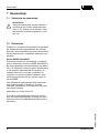
1 Zu Ihrer Sicherheit
1.1 Autorisiertes Personal
Sämt
liche in dieser Betriebsanleitung beschriebe-
nen Handhabungen dürfen nur durch ausgebilde-
tes und vom Anlagenbetreiber autorisiertes Fach-
personal durchgeführt werden. Eingriffe darüber
hinaus dürfen aus Sicherheits- und Gewährleis-
tungsgründen nur durch vom Hersteller autorisier-
tes Personal vorgenommen werden.
1.2 Bestimmungsgemäße Verwendung
Der VEGAWAVE S 61 ist ein Sensor zur Grenz-
standerfassung.
Detaillierte Angaben zum Einsatzbereich des VE-
GAWAVE S 61 finden Sie im Kapitel "Produktbe-
schreibung".
1.3 Warnung vor Fehlgebrauch
Bei nicht sachgerechter oder nicht bestimmungs-
gemäßer Verwendung können von diesem Gerät
anwendungsspezifische Gefahren ausgehen, so z.
B. ein Überlauf des Behälters oder Schäden an
Anlagenteilen durch falsche Montage oder Ein-
stellung.
1.4 Allgemeine Sicherheitshinweise
Der VEGAWAVE S 61 entspricht dem Stand der
Technik unter Beachtung der üblichen Vorschriften
und Richtlinien. Durch den Anwender sind die
Sicherheitshinweise in dieser Betriebsanleitung,
die landesspezifischen Installationsstandards (z. B.
in Deutschland die VDE-Bestimmungen) sowie die
geltenden Sicherheitsbestimmungen und Unfall-
verhütungsvorschriften zu beachten.
1.5 CE-Konformität
Der VEGAWAVE S 61 ist CE-konform zum EMVG
(89/336/EWG), erfüllt die NAMUR-Empfehlung
NE 21 und ist CE-konform zur NSR (73/23/EG).
Die Konformität wurde nach folgenden Normen
bewertet:
l EMVG:
- Emission EN 61326: 1997 (Klasse B)
- Immissi
on EN 61326: 1997/A1: 1998
l NSR: EN 61010-1: 2001
1.6 Sicherheitshinweise für Ex-Bereiche
Beachten Sie bei Ex-Anwendungen die Ex-spezi-
fischen Sicherheitshinweise. Diese sind Bestand-
teil der Betriebsanleitung und liegen jedem Gerät
mit Ex-Zulassung bei.
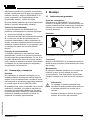
2 Produktbeschreibung
2.1 Aufbau
Lieferumfang
Der Lieferu
mfa
ng besteht aus:
l Grenzstandsensor VEGAWAVE S 61
l Dokumentation
- Dieser Betriebsanleitung
- Ex-spezifischen "Sicherheitshinweisen"
(bei Ex-Ausführungen)
2.2 Arbeitsweise
Einsatzbereich
Der VEGAWAVE S 61 ist ein Grenzstandsensor
mit Schwinggabel zur Grenzstanderfassung.
Er ist konzipiert für industrielle Einsätze in allen
Bereichen der Verfahrenstechnik und wird vor-
zugsweise in Schüttgütern eingesetzt.
Typische Anwendungen sind Überlauf- und Tro-
ckenlaufschutz. Durch sein einfaches und robustes
Messsystem lässt sich der VEGAWAVE S 61
nahezu unabhängig von den chemischen und
physikalischen Eigenschaften des Schüttgutes
einsetzen.
Er arbeitet auch unter starken Fremdvibrationen
oder bei wechselndem Füllgut.
Funktionsüberwachung
Der Elektronikeinsatz des VEGAWAVE S 61
überwacht kontinuierlich folgende Kriterien:
VEGAWAVE S 61 3
Zu Ihrer Sicherheit
32949-01-080108

l Korrekte Schwingfrequenz
l Leitungsbruch zum Piezoantrieb
Wird eine der genannten Funktionsstörungen
erkannt oder fällt die Spannungsversorgung aus,
so nimmt die Elektronik einen definierten Schalt-
zustand an, d. h. das Relais wird stromlos (sicherer
Zustand).
Funktionsprinzip
Die Schwinggabel wird piezoelektrisch angetrieben
und schwingt auf ihrer mechanischen Resonanz-
frequenz von ca. 150 Hz. Wird die Schwinggabel
mit Füllgut bedeckt, ändert sich die Schwingam-
plitude. Diese Änderung wird vom eingebauten
Elektronikeinsatz erfasst und in einen Schaltbefehl
umgewandelt.
2.3 Lagerung und Transport
Verpackung
Ihr Gerät wurde auf dem Weg zum Einsatzort durch
eine Verpackung geschützt. Dabei sind die übli-
chen Transportbeanspruchungen durch eine Prü-
fung nach DIN EN 24180 abgesichert.
Die Verpackung besteht aus Karton, ist umwelt-
verträglich und wieder verwertbar. Der Messfühler
ist zusätzlich mit einer Schutzkappe aus Pappe
versehen. Entsorgen Sie das anfallende Verpa-
ckungsmaterial über spezialisierte Recyclingbe-
triebe.
3 Mon
tieren
3.1 Allgemeine Hinweise
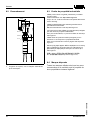
Schaltpunkt
G
rundsätzlich kann der VEGAWAVE S 61 in jeder
beliebigen Lage eingebaut werden. Das Gerät
muss lediglich so montiert werden, dass sich das
Schwingelement auf Höhe des gewünschten
Schaltpunktes befindet.
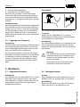
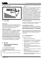
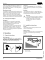
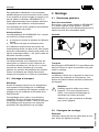
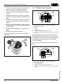
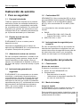
Feuchtigkeit
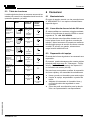
Abb. 1: Maßnahmen gegen das Eindringen von Feuchtigkeit
Transport
Halten Sie den VEGAWAVE S 61 nicht am
Schwingelement. Entfernen Sie die Schutzkappe
erst unmittelbar vor dem Einbau.
Handhabung
Der Vibrationsgrenzschalter ist ein Messgerät und
muss entsprechend behandelt werden. Ein Ver-
biegen des Schwingelements führt zur Zerstörung
des Gerätes.
Warnung:
Das Gehäuse darf nicht zum Einschrauben
verwendet werden! Das Festziehen kann
Schäden an der Drehmechanik des Geh-
äuses verursachen.
Verwenden Sie zum Einschrauben den
Sechskant oberhalb des Gewindes.
3.2 Montagehinweise
Stutzen
Das Schwingelement sollte möglichst f rei in den
Behälter ragen, um Ablagerungen zu verhindern.
Befüllöffnung
Bauen Sie das Gerät so ein, dass die Schwing-
gabel nicht direkt in den Befüllstrom ragt.
4 VEGAWAVE S 61
Montieren
32949-01-080108

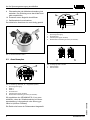
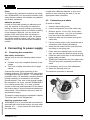
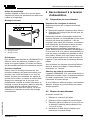
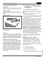
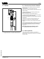
Horizontaler Einbau
20°
a.
b.
Abb. 2: Horizontaler Einbau
a Konvexe Montage
b Konkave Montage
Strömungen
Damit die Schwingga
bel des VEGAWAVE S 61 bei
Füllgutbewegungen möglichst wenig Widerstand
bietet, sollten die Flächen der Schwinggabel
parallel zur Füllgutbewegung stehen.
Anhaftende Füllgüter
Bei horizontalem Einbau in anhaftenden Füllgütern
sollten die Flächen der Schwinggabel möglichst
senkrecht stehen, um Ablagerungen auf der
Schwinggabel möglichst gering zu halten. Bei der
Gewindeausführung ist eine Markierung auf dem
Sechskant. Damit können Sie die Stellung der
Schwinggabel beim Einschrauben kontrollieren.
Wenn der Sechskant auf der Flachdichtung auf-
sitzt, kann das Gewinde noch ca. um eine halbe
Umdrehung weitergedreht werden. Das genügt,
um die empfohlene Einbaulage zu erreichen.
4 An
die
Span
nungsv
ersorgung
anschließen
4.1 Anschluss
vorbereiten
Sicherh
eitshinweise beachten
Beachten Sie grundsätzlich folgende Sicherheits-
hinweise:
l Nur in spannungslosem Zustand anschließen
l Sicherheitshinweise für Ex-Anwendungen be-
achten
Schließen Sie die Versorgungsspannung gemäß
den nachfolgenden Anschlussbildern an. Der
Elektronikeinsatz mit Relaisausgang ist in Schutz-
klasse 1 ausgeführt. Zur Einhaltung dieser
Schutzklasse ist es zwingend notwendig, dass der
Schutzleiter an der inneren Schutzleiteranschluss-
klemme angeschlossen wird. Beachten Sie dazu
die allgemeinen Installationsvorschriften. Verbin-
den Sie den VEGAWAVE S 61 grundsätzlich mit
der Behältererde (PA) bzw. bei Kunststoffbehältern
mit dem nächstgelegenen Erdpotenzial. Seitlich
am Gerätegehäuse befindet sich dazu eine Er-
dungsklemme zwischen den Kabelverschraubun-
gen. Diese Verbindung dient zur Ableitung elekt-
rostatischer Aufladungen.
Die Daten für die Spannungsversorgung finden Sie
im Kapitel "Technische Daten" im "Anhang".
Anschlusskabel auswählen
Der VEGAWAVE S 61 wird mit handelsüblichem
Kabel mit rundem Querschnitt angeschlossen. Ein
Kabelaußendurchmesser von 5 … 9 mm gewähr-
leistet die Dichtwirkung der Kabelverschraubung.
Wenn Sie Kabel mit anderem Durchmesser oder
Querschnitt einsetzen, wechseln Sie die Dichtung
oder verwenden Sie eine geeignete Kabelver-
schraubung.
4.2 Anschlussschritte
Gehen Sie wie folgt vor:
1 Gehäusedeckel abschrauben
2 Überwurfmutter der Kabelverschraubung lösen
3 Anschlusskabel ca. 10 cm (4 in) abmanteln,
Aderenden ca. 1 cm (0.4 in) abisolieren
4 Kabel durch die Kabelverschraubung in den
Sensor schieben
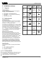
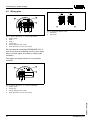
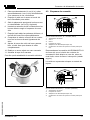
5 Öffnungshebel der Klemmen mit einem
Schraubendreher anheben (siehe nachfolgen-
de Abbildung)
6 Aderenden nach A nschlussplan in die offenen
Klemmen stecken
7 Öffnungshebel der Klemmen nach unten drü-
cken, die Klemmenfeder schließt hörbar
8 Korrekten Sitz der Leitungen in den Klemmen
durch leichtes Ziehen prüfen
VEGAWAVE S 61 5
An die Spannungsversorgung anschließen
32949-01-080108

9 Überwurfmutter der Kabelverschraubung fest
anziehen. Der Dichtring muss das Kabel kom-
plett umschließen
10 Eventuell neuen Abgleich durchführen
11 Gehäusedeckel verschrauben
Der elektrische Anschluss ist somit fertig gestellt.
Abb. 3: Anschlussschritte 5 und 6
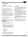
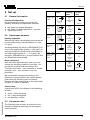
4.3 Anschlussplan
3
L
N
1 2 3 4 5 6 7 8
min max
4 5 6 7 8
1 2 3
5
4
6
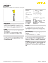
Abb. 4: Ausführung: Elektronik „R“ - Doppelrelais (DPDT)
1 Spannungsversorgung
2 Relais 1
3 Relais 2
4 Kontrollleuchte
5 Dichteanpassung (DIL-Schalter)
6 Betriebsartenumschaltung min/max (DIL-Schalter)
Wir empfehlen den VEGAWAV
E S 61 so anzu-
schließen, dass der Schaltstromkreis bei Grenz-
standmeldung, Leitungsbruch oder Störung ge-
öffnet ist (sicherer Zustand).
Die Relais sind immer im Ruhezustand dargestellt.
1 2 3 4
min max
1 2 3 4
1
3
2
4
Abb. 5: Ausführung: Elektronik „T“ - Transistor (NPN/PNP)
1 Spannungsversorgung
2 Kontrollleuchte
3 Dichteanpassung (DIL-Schalter)
4 Betriebsartenu
mschaltung min/max (DIL-Schalter)
+
-
+
-
+
-
+
-
1 2
Abb. 6: Belegung: NPN und PNP
1 NPN-Verhalten
2 PNP-Verhalten
6 VEGAWAVE S 61
An die Spannungsversorgung anschließen
32949-01-080108

5 In Betrieb nehmen
5.1 Allgemein
Funktion/Aufbau
Auf dem Ele
ktronikeinsatz finden Sie folgende
Anzeige- und Bedienelemente:
l DIL-Schalter zur Dichteanpassung
l DIL-Schalter zur Betriebsartenumschaltung -
min./max.
l Kontrollleuchte (LED)
5.2 Bedienelemente
Dichteanpassung
Mit diesem DIL-Schalter können Sie den Schalt-
punkt auf Schüttgüter einstellen, die eine Dichte
zwischen 0,1 und 0,3 g/cm³ haben.
Der Schalter des VEGAWAVE S 61 steht ab Werk
auf dem großen Gewichtssymbol (> 0,3 g/cm³). Bei
besonders leichten Schüttgütern stellen Sie den
DIL-Schalter auf das kleine Gewichtssymbol
(0,1 … 0,3 g/cm³). Damit wird der VEGAWAVE S
61 empfindlicher und kann leichte Schüttgüter
sicher detektieren.
Betriebsartenumschaltung
Mit der Betriebsartenumschaltung (min./max.)
können Sie den Schaltzustand des Relais ändern.
Sie können damit die gewünschte Betriebsart
gemäß "Funktionstabelle" einstellen (max. - Maxi-
malstanderfassung bzw. Überlaufschutz, min. -
Minimalstanderfassung bzw. Trockenlaufschutz).
Wir empfehlen, den Anschluss im Ruhestrom-
prinzip (Relaiskontakt bei Erreichen des Schalt-
punktes stromlos), da das Relais bei erkannter
Störung den gleichen (sicheren) Zustand annimmt.
Kontrollleuchte
Kontrollleuchte (LED) zur A nzeige des Schaltzu-
standes
l grün = Relais stromführend
l rot = Relais stromlos
l rot (blinkt) = Störung
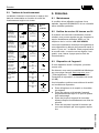
5.3 Funktionstabelle
Die folgende Tabelle gibt eine Übersicht über die
Schaltzustände in Abhängigkeit von der einge-
stellten Betriebsart und dem Füllstand.
Füllstand Schaltzu-
stand
Kontroll-
leuchte
Betriebs
art
max.
Überlauf-
schutz
Relais strom-
führend
oder
Transistor lei-
tet
Grün
Betriebsart
max.
Überlauf-
schutz
Relais strom-
los
oder
Transistor
sperrt
Rot
Betriebsart
min.
Trockenlauf-
schutz
Relais strom-
führend
oder
Transistor lei-
tet
Grün
Betriebsart
min.
Trockenlauf-
schutz
Relais strom-
los
oder
Transistor
sperrt
Rot
Ausfall der
Spannungs-
versorgung
(Betriebsart
min./max.)
beliebig
Relais strom-
los
oder
Transistor
sperrt
Störung beliebig
Relais strom-
los
oder
Transistor
sperrt
blinkt rot
VEGAWAVE S 61 7
In Betrieb nehmen
32949-01-080108

6 Instandhalten
6.1 Wartung
Der VEGAWAVE
S 61 bedarf bei bestimmungs-
gemäßer Verwendung keiner besonderen War-
tung.
6.2 24 Stunden Service-Hotline
Sollten diese Maßnahmen dennoch zu keinem
Ergebnis führen, rufen Sie in dringenden Fällen die
VEGA Service-Hotline an unter Tel.
+49 1805 858550.
Die Hotline steht Ihnen auch außerhalb der
üblichen Geschäftszeiten an 7 Tagen in der Woche
rund um die Uhr zur Verfügung. Da wir diesen
Service weltweit anbieten, erfolgt die Unterstützung
in englischer Sprache. Der Service ist kostenlos,
es fallen lediglich die üblichen Telefongebühren an.
6.3 Das Gerät reparieren
Sollte eine Reparatur erforderlich sein, gehen Sie
folgendermaßen vor:
Im Internet können Sie auf unserer Homepage
www.vega.com unter: "Downloads - Formulare und
Zertifikate - Reparaturformular" ein Rücksendefor-
mular (23 KB) herunterladen.
Sie helfen uns damit, die Reparatur schnell und
ohne Rückfragen durchzuführen.
l Für jedes Gerät ein Formular ausdrucken und
ausfüllen
l Das Gerät reinigen und bruchsicher verpacken
l Dem Gerät das ausgefüllte Formular und
eventuell ein Sicherheitsdatenblatt beilegen
l Bitte erfragen Sie die Adresse für die Rück-
sendung bei Ihrer jeweiligen Vertretung
7 Au
sbauen
7.1 Ausbauschr
itte
Warnung:
Achten Sie vor dem Ausbauen auf gefähr-
liche Prozessbedingungen wie z. B. Druck
im Behälter, hohe Temperaturen, aggres-
sive oder toxische Füllgüter etc.
7.2 Entsorgen
Das Gerät besteht aus Werkstoffen, die von darauf
spezialisierten Recyclingbetrieben wieder verwer-
tet werden können. Wir haben hierzu die Elektro-
nikeinsätze leicht trennbar gestaltet und verwen-
den recyclebare Werkstoffe.
WEEE-Richtlinie 2002/96/EG
Das vorliegende Gerät unterliegt nicht der WEEE-
Richtlinie 2002/96/EG und den entsprechenden
nationalen Gesetzen (in Deutschland z. B. Elekt-
roG). Führen Sie das Gerät direkt einem speziali-
sierten Recyclingbetrieb zu und nutzen Sie dafür
nicht die kommunalen Sammelstellen. Diese dür-
fen nur für privat genutzte Produkte gemäß WEEE-
Richtlinie genutzt werden.
Eine fachgerechte Entsorgung vermeidet negative
Auswirkungen auf Mensch und Umwelt und
ermöglicht eine Wiederverwendung von wertvollen
Rohstoffen.
Werkstoffe: siehe Kapitel "Technische Daten"
Sollten Sie keine Möglichkeit haben, das Altgerät
fachgerecht zu entsorgen, so sprechen Sie mit uns
über Rücknahme und Entsorgung.
8 VEGAWAVE S 61
Instandhalten
32949-01-080108

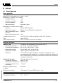
8 Anhang
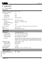
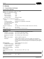
8.1 Technische Daten
Allgemeine Daten
Werkstoff 316L entsp
richt 1.4404 oder 1.4435
Werkstoffe, medienberührt
- Schwinggabel 316L
- Prozessanschluss 316L
- Verlängerungsrohr 316L
- Prozessdichtung Klingersil C-4400
Werkstoffe, nicht medienberührt
- Gehäuse Kunststoff PBT (Polyester)
- Gehäusedeckel Kunststoff PA 12 (Polyamid, klar)
- Dichtring (Gehäuse/Ge-
häusedeckel)
Silikon
- Erdungsklemme 316L
Sensorlänge (L) 165, 500, 1000 oder 1500 mm (6.496, 19.69, 39.37, 59.06 in)
Gewicht ca. 1500 g
Max. seitliche Belastung 600 N längs zur Gabelseite
Ausgangsgröße
Relaisausgang 2 potenzialfreie Umschaltkontakte (DPDT)
- Schaltspannung min. 10 mV / max. 253 V AC/DC
- Schaltstrom min. 10 µA / max. 3 A AC, 1 A DC
- Schaltleistung min. 50 mW / max. 750 VA, 54 W
- Kontaktwerkstoff AgNi oder AgSnO und Au plattiert
- Hinweis Wenn induktive Lasten oder höhere Ströme geschaltet werden, wird die
Goldplattierung auf der Relaiskontaktfläche dauerhaft beschädigt. Der
Kontakt ist danach nicht mehr zum Schalten von Kleinsignalstromkreisen
geeignet.
Transistorausgang Potenzialfreier Transistorausgang
- Schaltspannung max. 55 V DC
- Schaltstrom max. 400 mA
- Sperrstrom < 100 µA
Betriebsarten (umschaltbar) min./max.
Schaltverzögerung ein: ca. 0,5 sek. / aus: ca. 1 sek .
Umgebungsbedingungen
Umgebungstemperatur -40 … +80 °C
Lager- und Transporttempe-
ratur
-40 … +80 °C
VEGAWAVE S 61 9
Anhang
32949-01-080108

Prozessbedingungen
Prozessdruck -1 … 25 bar/-100 … 2500 kPa
Prozesstemperatur -50 … +150 °C
Dichte > 0,1 g/cm³
Elektromechanische Daten
Kabeleinführung/Stecker (je
nach Ausführung)
1 x Kabelverschraubung M20 x 1,5 (Kabel: ø 5 … 9 mm), 1 x
Blindstopfen M20 x 1,5; beiliegend 1 x Kabelverschraubung M20 x 1,5
Federkraftklemmen für Leitungsquerschnitt bis 1,5 mm² (AWG 16)
Bedienelemente
Betriebsartenschalter
- Min. Minimalstanderfassung bzw. Trockenlaufschutz
- Max. Maximalstanderfassung bzw. Überlaufschutz
Spannungsversorgung
Versorgungsspannung 20 … 253 V AC, 50/60 Hz, 20 … 72 V DC (bei U > 60 V DC darf die
Umgebungstemperatur max. 50 °C betragen)
Leistungsaufnahme 1 … 8 VA (AC), ca. 1,3 W (DC)
Elektrische Schutzmaßnahmen
Schutzart IP 66/IP 67
Überspannungskategorie III
Schutzklasse I
Zulassungen
ATEX II 1/3 D IP66 T (optional)
10 VEGAWAVE S 61
Anhang
32949-01-080108

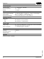
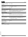
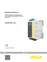
8.2 Maße
~ 69 mm
ø 81 mm
M20 x 1,5
153 mm
22 mm
L
95 mm
ø 43 mm
G1½ A
SW 46
Abb. 7: VEGAWAVE S 61
L Sensorlänge, siehe Kapitel "Technische Daten"
8.3 Gewerbliche Schutzrechte
VEGA product lines are global protected by industrial
property rights.
Further information see http://www.vega.com.
Only in U.S.A.: Further information see patent label at the
sensor housing.
VEGA Produktfamilien sind weltweit geschützt durch
gewerbliche Schutzrechte.
Nähere Informationen unter http://www.vega.com.
Les
lignes
de produits
VEGA sont globalement protégées
par des droits de propriété intellectuelle.
Pour plus d'informations, on pourra se référer au site
http://
www.veg
a.com.
VEGA lineas de productos
están protegidas por los
derechos en el campo de la propiedad industrial.
Para mayor información revise la pagina web http://www.
vega.com.
Линии продукции фирмы ВЕГА защищаются по всему
миру правами на интеллектуальную собственность.
Дальнейшую информацию смотрите на сайте http://
www.vega.com.
伟德(
VEGA)系列产品在全球享有知识产权保护。
进一步信息请参见网站<http://www.vega.com>。
8.4 Warenzeichen
Alle verwendeten Marken sowie Handels- und
Firmennamen sind Eigentum ihrer rechtmäßigen
Eigentümer/Urheber.
VEGAWAVE S 61 11
Anhang
32949-01-080108

Operating instructions manual
Betriebsanleitung 1
Operating instructions manual 12
Manuel de mise en service 22
Instrucción de servicio 33
Content
1 Content 12
2 For your
safety 13
2.1 Authorised personnel 13
2.2 Appropriate use 13
2.3 Warning about misuse 13
2.4 General safety instructions 13
2.5 CE conformity 13
2.6 Safety instructions for Ex areas 13
3 Product description 13
3.1 Configuration 13
3.2 Principle of operation 13
3.3 Storage and transport 14
4 Mounting 14
4.1 General instructions 14
4.2 Installation instructions 14
5 Connecting to power supply 15
5.1 Preparing the connection 15
5.2 Connection procedure 15
5.3 Wiring plan 16
6 Set up 17
6.1 General information 17
6.2 Adjustment elements 17
6.3 Functional chart 17
7 Maintain 18
7.1 Maintenance 18
7.2 24 hour service hotline 18
7.3 Instrument repair 18
8 Dismounting 18
8.1 Dismounting steps 18
8.2 Disposal 18
9 Supplement 19
9.1 Technical data 19
9.2 Dimensions 20
9.3 Industrial property rights 21
9.4 Trademark 21
12 VEGAWAVE S 61
32949-01-080108

Operating instructions manual
1 For your safety
1.1 Authorised personnel
All operations
described in this operating instruc-
tions manual must be carried out only by trained
specialist personnel authorised by the operator.
For safety and warranty reasons, any internal work
on the instruments must be carried out only by
personnel authorised by the manufacturer.
1.2 Appropriate use
VEGAWAVE S 61 is a sensor for level detection.
You can find detailed information on the application
range of VEGAWAVE S 61 in chapter "Product
description".
1.3 Warning about misuse
Inappropriate or incorrect use of the instrument can
give rise to application-specific hazards, e.g.
vessel overfill or damage to system components
through incorrect mounting or adjustment.
1.4 General safety instructions
VEGAWAVE S 61 is a high-tech instrument
requiring the strict observance of standard regu-
lations and guidelines. The user must take note of
the safety instructions in this operating instructions
manual, the country-specific installation standards
(e.g. in Germany the VDE reguations) as well as all
prevailing safety regulations and accident preven-
tion rules.
1.5 CE conformity
VEGAWAVE S 61 is in CE conformity with EMC
(89/336/EWG), fulfils NAMUR recommendation
NE 21 and is in CE conformity with LVD (73/23/
EG).
Conformity has been judged according to the
following standards:
l EMC:
- Emission EN 61326: 1997 (class B)
- Susceptibility EN 613
26: 1997/A1:199
8
l LVD: EN 61010-1: 2001
1.6 Safety instructions for Ex areas
Please note the Ex-specific safety information for
installation and operation in Ex areas. These safety
instructions are part of the operating instructions
manual and come with the Ex-approved instru-
ments.
2 Prod
uct description
2.1 Configuration
Scope of
delive
ry
The scope of delivery encompasses:
l VEGAWAVE S 61 level sensor
l Documentation
- this operating instructions manual
- Ex-specific "Safety instructions" (with Ex-
versions)
2.2 Principle of operation
Area of application
VEGAWAVE S 61 is a level sensor with tuning fork
for level detection.
It is designed for industrial use in all areas of
process technology and is preferably used for bulk
solids.
Typical applications are overfill and dry run
protection. Thanks to its simple and robust
measuring system, VEGAWAVE S 61 is virtually
unaffected by the chemical and physical properties
of the bulk solid.
It functions even when exposed to strong external
vibrations or changing products.
Fault monitoring
The electronics module of VEGAWAVE S 61
monitors continuously the following criteria:
l Correct vibrating frequency
l Line break to the piezo drive
VEGAWAVE S 61 13
For your safety
32949-01-080108

If one of the stated malfunctions is detected or in
case of power failure, the electronics takes on a
defined switching condition, i.e. the relay deener-
gises (safe condition).
Functional principle
The tuning fork is piezoelectrically energised and
vibrates at its mechanical resonance frequency of
approx. 150 Hz. When the tuning fork is sub-
merged in the product, the vibration amplitude
changes. This change is detected by the integrated
oscillator and converted into a switching command.
2.3 Storage and transport
Packaging
Your instrument was protected by packaging
during transport. Its capacity to handle normal
loads during transport is assured by a test
according to DIN EN 24180.
The packaging consists of environment-friendly,
recyclable cardboard. In addition, the sensor is
provided with a protective cover of cardboard.
Dispose of the packaging material via specialised
recycling companies.
3 Mou
nting
3.1 General instructions
Switching point
In general, VEGAWAVE S 61 can be installed in
any position. The instrument simply has be
mounted in such a way that the vibrating element is
at the height of the desired switching point.
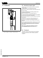
Moisture
Fig. 8: Measures against moisture penetration
Tr
ansport
Do not
hold VE
GAWAVE S 61 on the vibrating
element. Remove the protective cover just before
installation.
Handling
The vibrating level switch is a measuring instru-
ment and must be treated accordingly. Bending the
vibrating element will destroy the instrument.
Warning:
The housing must not be used to screw the
instrument in! Applying tightening force can
damage internal parts of the housing.
Use the hexagon above the thread for
screwing in.
3.2 Installation instructions
Socket
The vibrating element should protrude into the
vessel to avoid buildup.
Filling opening
Mount the instrument in such a way that the tuning
fork does not protrude directly into the filling
stream.
Horizontal mounting
20°
a.
b.
Fig. 9: H orizontal mounting
a Convex mounting
b Concave mounting
14 VEGAWAVE S 61
Mounting
32949-01-080108

Flows
To minimise flow resistance caused by the tuning
fork, VEGAWAVE S 61 should be mounted in such
a way that the surfaces of the blades are parallel to
the product movement.
Adhesive products
In case of horizontal mounting in adhesive prod-
ucts, the surfaces of the tuning fork should be
vertical in order to reduce buildup on the tuning
fork. On the screwed version you will find a marking
on the hexagon. With this, you can check the
position of the tuning fork when screwing it in.
When the hexagon touches the seal, the thread
can still be turned by approx. half a turn. This is
sufficient to reach the recommended installation
position.
4 Con
necting to power supply
4.1 Preparing the
connection
Note safe
ty instructions
Always keep in mind the following safety instruc-
tions:
l Connect only in the complete absence of line
voltage
l Take note of safety instructions for Ex appli-
cations
Connect the power supply according to the
following diagrams. The oscillator with relay output
is designed in protection class 1. To maintain this
protection class, it is absolutely necessary that the
ground conductor is connected to the internal
ground terminal. Take note of the general installa-
tion regulations. As a rule, connect VEGAWAVE S
61 to vessel ground (PA), or in case of plastic
vessels, to the next ground potential. On the side of
the housing there is a ground terminal between the
cable entries. This connection serves to drain off
electrostatic charges.
The data for voltage supply are specified in chapter
"Technical data" in the "Supplement".
Selecting connection cable
VEGAWAVE S 61 is connected with standard four-
wire cable with round cross-section. An outer cable
diameter of 5 … 9 mm ensures the seal effect of
the cable entry.
If cable with a different diameter or wire cross
section is used, exchange the seal or use an
appropriate cable connection.
4.2 Connection procedure
Proceed as follows:
1 Unscrew the housing cover
2 Loosen compression nut of the cable entry
3 Remove approx. 10 cm (4 in) of the cable
mantle, strip approx. 1 cm (0.4 in) insulation
from the ends of the individual wires
4 Insert the cable into the sensor through the
cable entry
5 Lift the opening levers of the terminals with a
screwdriver (see following illustration)
6 Insert the wire ends into the open terminals
according to the wiring plan
7 Press down the opening levers of the termi-
nals, you will hear the terminal spring closing
8 Check the hold of the wires in the terminals by
lightly pulling on them.
9 Tighten the compression nut of the cable entry.
The seal ring must completely encircle the
cable
10 If necessary, carry out a fresh adjustment
11 Screw the housing cover on
The electrical connection is finished.
Fig. 10: Connection steps 5 and 6
VEGAWAVE S 61 15
Connecting to power supply
32949-01-080108

4.3 Wiring plan
3
L
N
1 2 3 4 5 6 7 8
min max
4 5 6 7 8
1 2 3
5
4
6
Fig. 11: Version: Electronics „R“ - double relay (DPDT)
1 Voltage supply
2 Relay 1
3 Relay 2
4 Control lamp
5 Density adaptation (DIL switch)
6 Mo
de adjustment min./max. (DIL switch)
We
recommend connecting VEGAWAVE S 61 in
such a way that the switching circuit is open when
there is a level signal, line break or failure (safe
condition).
The relays are always shown in non-operative
condition.
1 2 3 4
min max
1 2 3 4
1
3
2
4
Fig. 12: Version: Electronics „T“ - transistor (NPN/PNP)
1 Voltage supply
2 Control lamp
3 Density adaptation (DIL switch)
4 Mode adjustment min./max. (DIL switch)
+
-
+
-
+
-
+
-
1 2
Fig. 13: Assignment: NPN and PNP
1 NPN action
2 PNP action
16 VEGAWAVE S 61
Connecting to power supply
32949-01-080108

5 Set up
5.1 General information
Function/Confi
guration
On the electronics module you will find the
following indicating and adjustment elements:
l DIL switch for density adaptation
l DIL switch for mode adjustment - min./max.
l Signal lamp (LED)
5.2 Adjustment elements
Density adaptation
With this DIL switch, the switching point can be set
to bulk solids having a density between 0 .1 and
0.3 g/cm³.
As default setting, the switch of VEGAWAVE S 61
is set to the large weight symbol (> 0.03 g/cm³). In
very light solids you should turn the DIL switch to
the small weight symbol (0.1 … 0.3 g/cm³). By
doing this, VEGAWAVE S 61 is more sensitive and
can detect light solids reliably.
Mode adjustment
With the mode adjustment (min./max.) you can
change the switching condition of the relay. You
can set the required mode according to the
"Function chart" (max. - max. detection or overfill
protection, min. - min. detection or dry run
protection).
We recommend connecting according to the
quiescent current principle (relay contact deener-
gizes when the switching point is reached),
because the relay always takes on the same (safe)
condition if a failure is detected.
Control lamp
Control lamp (LED) for indication of the switching
condition
l green = relay energized
l red = relay deenergized
l red (flashing) = failure
5.3 Functional chart
The following chart provides an overview of the
switching conditions depending on the adjusted
mode and level.
Level Switching
status
Control
lamp
Mo
de max.
Overflow pro-
tection
Relay ener-
gized
or
transistor con-
ducts
Green
Mode max.
Overflow pro-
tection
Relay deener-
gized
or
transistor
blocks
Red
Mode min.
Dry run pro-
tection
Relay ener-
gized
or
transistor con-
ducts
Green
Mode min.
Dry run pro-
tection
Relay deener-
gized
or
transistor
blocks
Red
Failure of the
supply voltage
(min./max.
mode)
any
Relay deener-
gized
or
transistor
blocks
Failure any
Relay deener-
gized
or
transistor
blocks
flashes red
VEGAWAVE S 61 17
Set up
32949-01-080108

6 Maintain
6.1 Maintenance
When used as
directed in normal condition,
VEGAWAVE S 61 is maintenance-free.
6.2 24 hour service hotline
However, if these measures are not successful,
call the VEGA service hotline in urgent cases under
the phone no. +49 1805 858550.
The hotline is available to you 7 days a week
round-the-clock. Since we offer this service world-
wide, the support is only available in the English
language. The service is free of charge, only the
standard telephone costs will be charged.
6.3 Instrument repair
If a repair is necessary, please proceed as follows:
You can download a return form (23 KB) from the
Internet on our homepage
www.vega.com under:
"Downloads - Forms and certificates - Repair form".
By doing this you help us carry out the repair
quickly and without having to call for needed
information.
l Print and fill out one form per instrument
l Clean the instrument and pack it damage-proof
l Attach the completed form and probably a
safety data sheet to the instrument
l Please contact the agency serving you for the
address of the return shipment
7 Dism
ounting
7.1 Dismounting steps
Warning:
Before dismounting, be aware of dangerous
process conditions such as e.g. pressure in
the vessel, high temperatures, corrosive or
toxic products etc.
7.2 Disposal
The instrument consists of materials which can be
recycled by specialised recycling companies. We
use recyclable materials and have designed the
electronics module to be easily separable.
WEEE directive 2002/96/EG
This instrument is not subject to the WEEE
directive 2002/96/EG and the respective national
laws (in Germany, e. g. ElektroG). Pass the
instrument directly on to a specialised recycling
company and do not use the municipal collecting
points. These may be used only for privately used
products according to the WEEE directive.
Correct disposal avoids negative effects to persons
and environment and ensures recycling of useful
raw materials.
Materials: see chapter "Technical data"
If you cannot dispose of the instrument properly,
please contact us about disposal methods or
return.
18 VEGAWAVE S 61
Maintain
32949-01-080108

8 Supplement
8.1 Technical data
General
data
Material 316L corresponds to 1.4404 or 1.4435
Materials, wetted parts
- Tuning fork 316L
- Process fitting 316L
- Extension tube 316L
- Process seal Klingersil C-4400
Materials, non-wetted parts
- Housing plastic PBT (Polyester)
- Housing cover Plastic PA 12 (polyamide, clear)
- Seal ring (housing/hous-
ing cover)
Silicone
- Ground terminal 316L
Sensor length (L) 165, 500, 1000 or 1500 mm (6.496, 19.69, 39.37, 59.06 in)
Weight approx. 1500 g
Max. lateral load 600 N along the fork side
Output variable
Relay output 2 floating spdts (DPDT)
- Turn-on voltage min. 10 mV / max. 253 V AC/DC
- Switching current min. 10 µA / max. 3 A AC, 1 A DC
- Breaking capacity min. 50 mW / max. 750 VA, 54 W
- Contact material AgNi or AgSnO and Au plated
- Instruction If inductive loads or stronger currents are switched through, the gold
plating on the relay contact surface will be permanently damaged. The
contact is then no longer suitable for switching low-level signal circuits.
Transistor output Floating transistor output
- Turn-on voltage max. 55 V DC
- Switching current max. 400 mA
- Blocking current < 100 µA
Modes (adjustable) min./max.
Switching delay ON: approx. 0.5 sex. / OFF: approx. 1 sec.
Ambient conditions
Ambient temperature -40 … +80 °C
Storage and transport tem-
perature
-40 … +80 °C
VEGAWAVE S 61 19
Supplement
32949-01-080108

Process conditions
Process pressure -1 … 25 bar/-100 … 2500 kPa
Process temperature -50 … +150 °C
Density > 0.1 g/cm³
Electromechanical data
Cable entry/plug (dependent
on the version)
1 x cable entry M20 x 1.5 (cable: ø 5 … 9 mm), 1 x blind stopper
M20 x 1.5; attached 1 x cable entry M20 x 1.5
Spring-loaded terminals for wire cross-section up to 1.5 mm² (AWG 16)
Adjustment elements
Mode switch
- Min. Min. detection or dry run protection
- Max. Max. detection or overfill protection
Voltage supply
Supply voltage 20 … 253 V AC , 50/60 Hz, 20 … 72 V DC (at U > 60 V DC, the ambient
temperature can be max. 50 °C/122 °F)
Power consumption 1 … 8 VA (AC), approx. 1.3 W (DC)
Electrical protective measures
Protection IP 66/IP 67
Overvoltage category III
Protection class I
Approvals
ATEX II 1/3 D IP66 T (optional)
20 VEGAWAVE S 61
Supplement
32949-01-080108
Seite wird geladen ...
Seite wird geladen ...
Seite wird geladen ...
Seite wird geladen ...
Seite wird geladen ...
Seite wird geladen ...
Seite wird geladen ...
Seite wird geladen ...
Seite wird geladen ...
Seite wird geladen ...
Seite wird geladen ...
Seite wird geladen ...
Seite wird geladen ...
Seite wird geladen ...
Seite wird geladen ...
Seite wird geladen ...
Seite wird geladen ...
Seite wird geladen ...
Seite wird geladen ...
Seite wird geladen ...
Seite wird geladen ...
Seite wird geladen ...
Seite wird geladen ...
Seite wird geladen ...
Seite wird geladen ...
Seite wird geladen ...
Seite wird geladen ...
Seite wird geladen ...
-
 1
1
-
 2
2
-
 3
3
-
 4
4
-
 5
5
-
 6
6
-
 7
7
-
 8
8
-
 9
9
-
 10
10
-
 11
11
-
 12
12
-
 13
13
-
 14
14
-
 15
15
-
 16
16
-
 17
17
-
 18
18
-
 19
19
-
 20
20
-
 21
21
-
 22
22
-
 23
23
-
 24
24
-
 25
25
-
 26
26
-
 27
27
-
 28
28
-
 29
29
-
 30
30
-
 31
31
-
 32
32
-
 33
33
-
 34
34
-
 35
35
-
 36
36
-
 37
37
-
 38
38
-
 39
39
-
 40
40
-
 41
41
-
 42
42
-
 43
43
-
 44
44
-
 45
45
-
 46
46
-
 47
47
-
 48
48


Vega VEGAWAVE 61 Bedienungsanleitung
- Typ
- Bedienungsanleitung
- Dieses Handbuch eignet sich auch für
in anderen Sprachen
- français: Vega VEGAWAVE 61 Mode d'emploi
- español: Vega VEGAWAVE 61 Instrucciones de operación
Verwandte Artikel
-
 Vega VEGAWAVE 61 Bedienungsanleitung
-
 Vega VEGAWAVE 61 Bedienungsanleitung
-
Vega VEGAWAVE 62 Bedienungsanleitung
-
Vega VEGAWAVE 63 Bedienungsanleitung
-
-
 Vega VEGAWAVE 61 Spezifikation
-
-
 Vega VEGATOR 122 Bedienungsanleitung
-
Vega VEGATOR 111 Bedienungsanleitung


