Yamaha CBX-D5 Benutzerhandbuch
- Kategorie
- Digitale Videorecorder (DVR)
- Typ
- Benutzerhandbuch

CBX-D5
DIGITAL RECORDING PROCESSOR
Owner's Manual 2
OPERATING MANUAL

* This applies only to products distributed by YAMAHA CORPORATION OF AMERICA
FCC INFORMATION (U.S.A.)
1. IMPORTANT NOTICE: DO NOT MODIFY THIS UNIT!
This product, when installed as indicated in the instructions contained in this manual, meets FCC requirements. Modifications not expressly approved by
Yamaha may void your authority, granted by the FCC, to use the product.
2. IMPORTANT: When connecting this product to accessories and/or another product use only high quality shielded cables. Cable/s supplied with this product
MUST be used. Follow all installation instructions. Failure to follow instructions could void your FCC authorization to use this product in the USA.
3. NOTE: This product has been tested and found to comply with the requirements listed in FCC Regulations, Part 15 for Class “B” digital devices. Compliance
with these requirements provides a reasonable level of assurance that your use of this product in a residential environment will not result in harmful interfer-
ence with other electronic devices. This equipment generates/uses radio frequencies and, if not installed and used according to the instructions found in the
users manual, may cause interference harmful to the operation of other electronic devices. Compliance with FCC regulations does not guarantee that interfer-
ence will not occur in all installations. If this product is found to be the source of interference, which can be determined by turning the unit “OFF” and “ON”,
please try to eliminate the problem by using one of the following measures:
Relocate either this product or the device that is being affected by the interference.
Utilize power outlets that are on different branch (circuit breaker or fuse) circuits or install AC line filter/s.
In the case of radio or TV interference, relocate/reorient the antenna. If the antenna lead-in is 300 ohm ribbon lead, change the lead-in to co-axial type cable.
If these corrective measures do not produce satisfactory results, please contact the local retailer authorized to distribute this type of product. If you can not
locate the appropriate retailer, please contact Yamaha Corporation of America, Electronic Service Division, 6600 Orangethorpe Ave, Buena Park, CA 90620
Dette apparat overholder det gaeldende EF-direktiv vedrørende
radiostøj.
Cet appareil est conforme aux prescriptions de la directive com-
munautaire 87/308/CEE.
Diese Geräte entsprechen der EG-Richtlinie 82/499/EWG und/
oder 87/308/EWG.
This product complies with the radio frequency interference
requirements of the Council Directive 82/499/EEC and/or 87/
308/EEC.
Questo apparecchio è conforme al D.M.13 aprile 1989 (Direttiva
CEE/87/308) sulla soppressione dei radiodisturbi.
Este producto está de acuerdo con los requisitos sobre interferen-
cias de radio frequencia fijados por el Consejo Directivo 87/308/
CEE.
YAMAHA CORPORATION
IMPORTANT NOTICE FOR THE UNITED KINGDOM
Connecting the Plug and Cord
IMPORTANT: The wires in this mains lead are coloured in accordance
with the following code:
GREEN-AND-YELLOW : EARTH
BLUE : NEUTRAL
BROWN : LIVE
As the colours of the wires in the mains lead of this apparatus may not
correspond with the coloured markings identifying the terminals in your
plug, proceed as follows:
The wire which is coloured GREEN and YELLOW must be connected to
the terminal in the plug which is marked by the letter E or by the safety
earth symbol or coloured GREEN and YELLOW.
The wire which is coloured BLUE must be connected to the terminal
which is marked with the letter N or coloured BLACK.
The wire which is coloured BROWN must be connected to the terminal
which is marked with the letter L or coloured RED.

SPECIAL MESSAGE SECTION
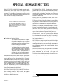
PRODUCT SAFETY MARKINGS: Yamaha electronic prod-
ucts may have either labels similar to the graphics shown
below or molded/stamped facsimiles of these graphics on the
enclosure. The explanation of these graphics appears on this
page. Please observe all cautions indicated on this page and
those indicated in the safety instruction section.
● Explanation of Graphical Symbols
The exclamation point within the equilat-
eral triangle is intended to alert the user to
the presence of important operating and
maintenance (servicing) instructions in the
literature accompanying the product.
The lightning flash with arrowhead symbol
within the equilateral triangle is intended to
alert the user to the presence of uninsulated
“dangerous voltage” within the product’s
enclosure that may be of sufficient magni-
tude to constitute a risk of electrical shock.
IMPORTANT NOTICE: All Yamaha electronic products are
tested and approved by an independent safety testing labora-
tory in order that you may be sure that when it is properly
installed and used in its normal and customary manner, all
foreseeable risks have been eliminated. DO NOT modify this
unit or commission others to do so unless specifically autho-
rized by Yamaha. Product performance and/or safety stan-
dards may be diminished. Claims filed under the expressed
warranty may be denied if the unit is/has been modified.
Implied warranties may also be affected.
SPECIFICATIONS SUBJECT TO CHANGE: The informa-
tion contained in this manual is believed to be correct at the
time of printing. However, Yamaha reserves the right to
change or modify any of the specifications without notice or
obligation to update existing units.
CAUTION: TO REDUCE THE RISK OF ELEC
-
TRIC SHOCK, DO NOT REMOVE COVER (O
R
BACK). NO USER-SERVICEABLE PART
S
INSIDE. REFER SERVICING TO QUALIFIE
D
SERVICE PERSONNEL.
ENVIRONMENTAL ISSUES: Yamaha strives to produce
products that are both user safe and environmentally friendly.
We sincerely believe that our products and the production
methods used to produce them, meet these goals. In keeping
with both the letter and the spirit of the law, we want you to
be aware of the following:
Battery Notice: This product MAY contain a small nonre-
chargeable battery which (if applicable) is soldered in place.
The average life span of this type of battery is approximately
five years. When replacement becomes neccessary, contact a
qualified service representative to perform the replacement.
Warning: Do not attempt to recharge, disassemble, or inciner-
ate this type of battery. Keep all batteries away from children.
Dispose of used batteries promptly and as regulated by appli-
cable laws. Note: In some areas, the servicer is required by
law to return the defective parts. However, you do have the
option of having the servicer dispose of these parts for you.
Disposal Notice: Should this product become damaged
beyond repair, or for some reason its useful life is considered
to be at an end, please observe all local, state, and federal reg-
ulations that relate to the disposal of products that contain
lead, batteries, plastics, etc.
NOTICE: Service charges incurred due to lack of knowledge
relating to how a function or effect works (when the unit is
operating as designed) are not covered by the manufacturer’s
warranty, and are therefore the owners responsibility. Please
study this manual carefully and consult your dealer before
requesting service.
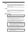
NAME PLATE LOCATION: The graphic below indicates the
location of the name plate. The model number, serial number,
power requirements, etc., are located on this plate. You
should record the model number, serial number, and the date
of purchase in the spaces provided below and retain this man-
ual as a permanent record of your purchase.
Model
Serial No.
Purchase Date
92-469 1

IMPORTANT SAFETY INSTRUCTIONS
INFORMATION RELATING TO PERSONAL INJURY, ELECTRICAL SHOCK,
AND FIRE HAZARD POSSIBILITIES HAS BEEN INCLUDED IN THIS LIST.
WARNING — When using any electrical or electronic prod-
uct, basic precautions should always be followed. These pre-
cautions include, but are not limited to, the following:
Read all Safety Instructions, Installation Instructions,
Special Message Section items, and any Assembly
Instructions found in this manual BEFORE making any con-
nections, including connection to the main supply.
Main Power Supply Verification: Yamaha products are
manufactured specifically for the supply voltage in the
area where they are to be sold. If you should move, or if any
doubt exists about the supply voltage in your area, please
contact your dealer for supply voltage verification and (if
applicable) instructions. The required supply voltage is
printed on the name plate. For name plate location, please
refer to the graphic found in the Special Message Section of
this manual.
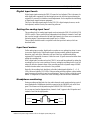
This product may be equipped with a polarized plug
(one blade wider than the other). If you are unable to
insert the plug into the outlet, turn the plug over and try again.
If the problem persists, contact an electrician to have the
obsolete outlet replaced. DO NOT defeat the safety purpose
of the plug.
Some electronic products utilize external power
supplies or adapters. DO NOT connect this type of
product to any power supply or adapter other than one
described in the owners manual, on the name plate, or specif-
ically recommended by Yamaha.
WARNING: Do not place this product or any other
objects on the power cord or place it in a position where
anyone could walk on, trip over, or roll anything over power
or connecting cords of any kind. The use of an extension cord
is not recommended! If you must use an extension cord, the
minimum wire size for a 25’ cord (or less) is 18 AWG.
NOTE: The smaller the AWG number, the larger the current
handling capacity. For longer extension cords, consult a local
electrician.
Ventilation: Electronic products, unless specifically
designed for enclosed installations, should be placed in
locations that do not interfere with proper ventilation. If
instructions for enclosed installations are not provided, it
must be assumed that unobstructed ventilation is required.
Temperature considerations: Electronic products
should be installed in locations that do not significantly
contribute to their operating temperature. Placement of this
product close to heat sources such as; radiators, heat registers
and other devices that produce heat should be avoided.
1.
2.
3.
4.
5.
6.
7.
This product was NOT designed for use in wet/damp
locations and should not be used near water or exposed
to rain. Examples of wet/damp locations are; near a swim-
ming pool, spa, tub, sink, or wet basement.
This product should be used only with the components
supplied or; a cart, rack, or stand that is recommended
by the manufacturer. If a cart, rack, or stand is used, please
observe all safety markings and instructions that accompany
the accessory product.
The power supply cord (plug) should be disconnected
from the outlet when electronic products are to be left
unused for extended periods of time. Cords should also be
disconnected when there is a high probability of lightening
and/or electrical storm activity.
Care should be taken that objects do not fall and liquids
are not spilled into the enclosure through any openings
that may exist.
Electrical/electronic products should be serviced by a
qualified service person when:
a. The power supply cord has been damaged; or
b. Objects have fallen, been inserted, or liquids have
been spilled into the enclosure through openings; or
c. The product has been exposed to rain; or
d. The product does not operate, exhibits a marked
change in performance; or
e. The product has been dropped, or the enclosure of
the product has been damaged.
Do not attempt to service this product beyond that
described in the user-maintenance instructions. All
other servicing should be referred to qualified service person-
nel.
This product, either alone or in combination with an
amplifier and headphones or speaker/s, may be capable
of producing sound levels that could cause permanent hearing
loss. DO NOT operate for a long period of time at a high vol-
ume level or at a level that is uncomfortable. If you experi-
ence any hearing loss or ringing in the ears, you should
consult an audiologist. IMPORTANT: The louder the sound,
the shorter the time period before damage occurs.
Some Yamaha products may have benches and/or
accessory mounting fixtures that are either supplied as a
part of the product or as optional accessories. Some of these
items are designed to be dealer assembled or installed. Please
make sure that benches are stable and any optional fixtures
(where applicable) are well secured BEFORE using. Benches
supplied by Yamaha are designed for seating only. No other
uses are recommended.
8.
9.
10.
11.
12.
13.
14.
15.
PLEASE KEEP THIS MANUAL
This information on safety is provided to comply with U.S.A. laws, but should be observed by users in all countiries.
92-469 2


1 Chapter : 1 Chapter :
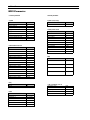
Table of Contents
1
Introduction
..............................................1
Welcome to the CBX-D5...............................1
CBX-D5 features............................................1
Operating manual organization......................1
Important Notice............................................1
Unpacking .....................................................2
Installation......................................................2
Trademarks.....................................................2
Powering up a CBX-D5 System ....................2
2
CBX-D5 Terminology
..........................3
3
What is the CBX-D5?
...........................5
Inside the CBX-D5.........................................6
The CBX-D5 in a MIDI recording system.....7
4
Controls & Connections
...................8
Front panel .....................................................8
Rear panel ....................................................10
5
Connecting Hard Disk Drives
......13
What type of hard disk?...............................13
Hard disk size...............................................13
Choosing a hard disk....................................14
SCSI ............................................................14
SCSI cables..................................................15
Computer connection...................................15
SCSI ID setting ............................................16
SCSI termination..........................................17
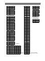
6
Working with Hard Disks
...............18
Formatting....................................................18
Sound file management................................18
Sound file backup.........................................18
Computer utilities.........................................18
Hard disk fragmentation...............................19
Hard disk partitioning ..................................19
7
Recording
................................................20
Sampling frequency (REC FREQ)...............20
Digital input levels.......................................21
Setting the analog input level.......................21
Input level meters.........................................21
Headphone monitoring.................................21
Digital audio data containing SCMS ...........22
Digital audio data with emphasis.................22
20-bit digital audio.......................................22
8
Playback
.................................................. 23
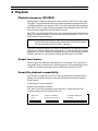
Playback frequency (PB FREQ) ................. 23
Output level meters ..................................... 23
Sound file playback compatibility............... 23
Sound file regions........................................ 24
9
Converting the Sampling
Frequency & Digital Audio
Format in Real Time
...................... 25
10
Inputs & Outputs Explained
..... 26
ANALOG IN............................................... 26
ANALOG OUT........................................... 26
AES/EBU IN 1/2......................................... 27
AES/EBU OUT 1/2, 3/4.............................. 27
CD/DAT IN................................................. 27
CD/DAT OUT............................................. 27
Y2 IN........................................................... 28
Y2 OUT....................................................... 28
WORD CLK IN/OUT................................. 28
11
TO HOST connection
.................... 30
MIDI ........................................................... 30
Mac ............................................................. 31
PC-1 ............................................................ 32
PC-2 ............................................................ 32
TO HOST computer connecting cables ...... 33
12
Glossary
............................................... 34
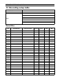
13
Recording setup table
.................. 36
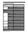
14
CBX-D5 Specifications
................ 37
Index
............................................................... 38
Appendix
.............................................. Add-1
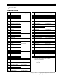
Preset Effects ................................. Add-1
DSP/DEQ/DMIX Block Diagram.. Add-2
Preset effects parameter values ..... Add-3
Data-Value Assign Table ............... Add-5
Effect parameters............................ Add-8
MIDI Parameter............................ Add-24
MIDI Data Format........................ Add-28
MIDI Implementation chart.......... Add-32

Introduction 1Introduction 1Introduction 1
1 Introduction
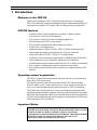
Welcome to the CBX-D5
Thank you for purchasing a CBX-D5 Digital Recording Processor. Connecting the
CBX-D5 to a controlling computer with supporting software and an external hard disk will
provide up to four channels of CD quality audio recording, processing, and playback.
CBX-D5 features
• 4-channel system: 2-channel simultaneous recording, 4-channel playback.
• A/D conversion: 16-bit linear ∆ Σ modulation.
• D/A conversion: 18-bit with 8-times oversampling digital filter.
• Multi-band parametric DEQ for each channel.
• DSP provides 82 different reverb and modulation type effects.
• 4-input, 4-bus, 2-send digital mixer.
• Sampling frequencies: 48kHz, 44.1kHz, 32kHz, (22.05kHz analog input only).
• Analog inputs and outputs use professional style XLR type connectors.
• Digital I/O includes AES/EBU, CD/DAT & Y2 Yamaha format.
• 10 minutes of stereo audio requires approximately 100MB hard disk (fs=44.1kHz).
• Total recording time can be increased by adding more SCSI hard disks.
• All audio data processing is carried out within the CBX-D5, so much less is demanded
of the computer, eliminating data bottlenecks and slow screen redraws.
• Host computer connection allows direct connection to a computer without a MIDI
interface.
Operating manual organization
The CBX-D5 is supplied with three manuals: this Operating Manual, the System Setup
Guide, and a Test Program manual.
This Operating Manual contains full details about the CBX-D5 Digital Recording
Processor: what it is, how it works, and how to use it. It also contains an index that will
allow you to locate information quickly, and also a glossary of CBX-D5 terminology.
The System Setup Guide describes how to set up a recording system using the current
supporting computers and music programs. From time to time this guide will be updated
using single sheet supplements. Please see your Yamaha dealer for the latest supplement.
The Test Program manual should be used in conjunction with the Hardware Test Program
Disk for testing the CBX-D5 hardware.
Important Notice
YAMAHA AND THE SOFTWARE COMPANIES THAT PRODUCE CBX-D5
CONTROLLING SOFTWARE CANNOT BE HELD RESPONSIBLE FOR ANY LOSS
OF DATA OR FOR ANY DIRECT, INDIRECT, SPECIAL INCIDENTAL,
CONSEQUENTIAL OR OTHER DAMAGES SUFFERED BY THE USER OR OTHERS
RESULTING FROM THE USE OR PURCHASE OF THE CBX-D5, ITS
DOCUMENTATION, OR SUPPORTING SOFTWARE.

2 Chapter 1 : Introduction2 Chapter 1 : Introduction2 Chapter 1 : Introduction
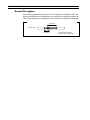
Unpacking
The CBX-D5 packaging should contain the following items.
Store the packaging materials for future use.
Installation
The cosmetic appearance of the CBX-D5 has been designed to match typical computer
hardware. Its “footprint” size matches that of many computers so that it can easily be
installed with your other computer equipment.
The CBX-D5 should be placed on a flat, stable surface.
The CBX-D5 can also be rack mounted using the supplied rack-mount kit. When installed
in the rack-mount kit the CBX-D5 requires 3U of rack space.
Trademarks
IBM
, PC-AT
, PS/1
, and PS/2
are registered trademarks of International Business
Machines Corporation.
Apple
and Macintosh
are registered trademarks of Apple Computer, Inc.
Atari
, ST
, TT
, and STE
are registered trademarks of Atari Corporation.
Mark of the Unicorn
is a registered trademark of Mark of the Unicorn, Inc.
All other trademarks are the property of their respective holders.
Powering up a CBX-D5 System
Some computer systems are a little bit fussy about which devices are switched on first,
especially when a SCSI daisy chain is introduced into the system. As a good rule of
thumb, switch on all connected SCSI devices first, then the computer.
1 CBX-D5 Serial No:
1 Power cable
1 8-pin mini DIN cable
1 MIDI cable
1 SCSI cable (50 to 50 Amphenol)
1 SCSI terminator
1 Rack-mount kit (L & R set)
1
Hardware Test Program Disk
1
Test Program Manual
1 This
Operating Manual
1
System Setup Guide
1 User Registration Card
NOTE: While using your CBX-D5 computer music system, do not switch off or
disconnect any device connected in the SCSI chain. Doing so will probably
lead to a system crash and you could loose valuable data.

CBX-D5 Terminology 3CBX-D5 Terminology 3CBX-D5 Terminology 3
2 CBX-D5 Terminology
SCSI
Pronounced scuzzy, the Small Computer System Interface is a connection format used for
connecting peripheral devices such as hard disks, printers, scanners, etc., to a computer.
Up to eight SCSI devices can be connected together in a daisy chain including the
controlling computer. Each device is given its own identity number from 0 to 7, this is
called the SCSI ID number.
The CBX-D5, a computer, and a hard disk are all connected as part of a SCSI daisy chain.
The SCSI connection carries audio data between the CBX-D5 and hard disk for recording
and playback, and also control data from the computer to the CBX-D5. The controlling
computer can also access the hard disk to perform basic sound file copy, delete, and backup
type functions. With the necessary software, digital audio data could be transferred
directly to the computer for on-screen waveform editing, etc.
The SCSI standard is quite a robust format, although, some care must be taken when
connecting and setting up SCSI devices. For full details about connecting SCSI hard disk
drives to the CBX-D5 see “Connecting Hard Disk Drives” on page 13.
Sound files
Just like other types of computer data, digital audio data is stored in files – sound files.
When recording starts, a sound file is created on the hard disk. This sound file can be given
a name, copied, and deleted just like any other computer file.
AES/EBU format
AES/EBU is a digital interface format established by the AES (Audio Engineering
Society) and EBU (European Broadcasting Union). It is used to transfer digital audio data
between professional digital audio equipment. Usually, two channels of digital audio (left
& right) are carried in one XLR type connection.
Although similar to the CD/DAT format, it is primarily intended for professional usage.
AES/EBU format connections can be found on most professional digital audio equipment
including hard disk recorders, digital mixers, professional DAT recorders, and many
digital VTRs.
CD/DAT format
Similar to the professional AES/EBU format, CD/DAT, or S/PDIF (Sony/Philips Digital
Interface Format) as it is otherwise known, is a digital interface format that is used to
transfer digital audio data between consumer type digital audio equipment such as CD
players, consumer DAT recorders, and the new DCC recorders.
Like the AES/EBU format, two channels of digital audio (left & right) are carried in one
connection, usually a phono/RCA jack type connection. Some MIDI samplers are fitted
with a CD/DAT connection so that sample data can be transferred directly to a DAT
recorder for storage.
Y2 format
Y2 Yamaha format is a digital interface format developed by Yamaha that is used to
transfer digital audio data between Yamaha’s professional digital audio equipment. Two
channels of digital audio (left & right) are carried in one connection, usually an 8-pin DIN
type connection.
Yamaha’s professional digital audio products usually include the AES/EBU and CD/DAT
type formats as well as Y2, and the Y2 format can also be found on some other
manufacturers’ digital audio products. Yamaha’s professional digital audio products that
use Y2 include the DMR8 Digital Mixer/Recorder, DMC1000 Digital Mixing Console,
DRU8 Digital Recorder, and the DMP series of Digital Mixers.

4 Chapter 2 : CBX-D5 Terminology4 Chapter 2 : CBX-D5 Terminology4 Chapter 2 : CBX-D5 Terminology
Sampling frequency (REC FREQ)
During the analog to digital conversion process, the level of the analog audio signal is
sampled (measured) many times per second. Each of these sample measurements is then
stored as a 16-bit binary value. For digital to analog conversion (playback), these 16-bit
binary values are used to reconstruct the analog audio signal. The rate at which these
sample measurements take place is called the sampling frequency and you may already
know that the sampling frequency used by CD players is 44.1kHz.
The CBX-D5 can record audio using any one of four sampling frequencies: 48kHz,
44.1kHz, 32kHz, and 22.05kHz. The audio quality (bandwidth) of a digital system is
directly affected by the sampling frequency. Essentially, the audio bandwidth will be
roughly half the chosen sampling frequency. See “Sampling frequency (REC FREQ)” on
page 20 for more details.
Word clock
When a number of digital audio devices are connected together and data is digitally
transferred between them, it is essential that the data processing circuits of all devices are
synchronized. To achieve this, one device operates as a word clock master and all other
devices operate as word clock slaves. The frequency of the word clock corresponds
directly to the digital audio data’s sampling frequency.
If you only connect two digital audio devices, say the CBX-D5 to a DAT recorder, word
clock setup is quite straight forward and no word clock connections will be required.
However, when three devices are connected, serious thought will need to be given as to
which device is word clock master and how to make the word clock connections. See
“WORD CLK IN/OUT” on page 28 for more details.
To Host
An 8-pin mini DIN connector that allows direct connection to a computer that is running
CBX-D5 supporting software. This can be used when your computer does not have a
MIDI interface, i.e. MIDI input and output connections. See “TO HOST connection” on
page 30 for more details.
NOTE:
Word clock signals should not be confused with other synchronizing signals
such as SMPTE timecode and MTC (MIDI Timecode). Although both may
be used in a digital audio system, word clocks are for synchronizing digital
audio data processing circuits such as CPUs, D/A, A/D converters, etc., while
SMPTE and MTC timecodes are for synchronizing audio and video tape
machines, MIDI sequencers, etc., relative to time – hours, minutes, seconds,
and frames.
NOTE:
Not all CBX-D5 supporting music software can use this type of connection,
so please consult your Yamaha dealer before making a purchase.

What is the CBX-D5? 5What is the CBX-D5? 5What is the CBX-D5? 5
3 What is the CBX-D5?
The CBX-D5 is a Digital Recording Processor that, when connected to a controlling
computer with supporting software and an external hard disk, provides up to four channels
of CD quality audio recording, processing, and playback.
Computer based
The CBX-D5 is controlled by a computer that is running CBX-D5 supporting software.
All audio data processing takes place inside the CBX-D5, so there is very little demand on
the controlling computer. For this reason the CBX-D5 can be used with some of the less
powerful, less expensive computers such as the Apple Macintosh SE/30, Classic II, and
LC; and the Atari ST/STE. It also leaves the computer free to get on with other jobs such
as processing MIDI sequence data and screen updates.
The CBX-D5, computer, and hard disk are all connected as part of a SCSI daisy chain. The
SCSI connection carries audio data between the CBX-D5 and hard disk for recording and
playback, and also control data from the computer to the CBX-D5. A MIDI connection
between the CBX-D5 and computer carries continuous controller information for
real-time volume, EQ, and pan control of the CBX-D5’s digital mixer.
Four-channel system
The CBX-D5 is a 4-channel system, i.e., 2-channel simultaneous recording and
4-channel playback. Channels can be recorded while other channels playback.
The CBX-D5 needs about 100Mbytes of hard disk space to record 10 minutes of stereo
digital audio (fs = 44.1kHz). The available recording time can be increased by simply
adding more, or larger hard disk drives to the SCSI daisy chain.
CD quality & editing
The CBX-D5 records audio data at a 16-bit resolution, and with 44.1kHz and 48kHz
sampling frequencies it provides all the sound quality benefits of the Compact Disc format
such as faithful reproduction, low noise, minimal distortion, etc.
Analog input and output signals are processed by 16-bit linear ∆ Σ modulation A/D and
18-bit 8-times oversampling D/A converters. Analog connections use balanced XLR type
connectors. Digital I/O consists of AES/EBU, CD/DAT, and Y2. Allowing digital audio
data transfer between the CBX-D5 and other digital audio equipment.
As well as the A/D, D/A converters, the CBX-D5 also contains a 4-input, 4-bus, 2-send
digital mixer; a DSP for digital effects; DEQ for real-time EQ control; and sampling
frequency converters that allow recording and playback at differing sampling frequencies.
As well as the sound quality, two other benefits of recording with a CBX-D5 system as
opposed to analog tape are, the ability to nondestructively edit recordings and being able
to move audio data relative to time, a feature often referred to as audio time slip.
For a listing of some other CBX-D5 features, see “CBX-D5 features” on page 1.
The future
The CBX-D5 is a software dependent device, so with future supporting software it may be
possible to use the CBX-D5 for digital mixing with digital EQ and effects, sampling,
2-track mastering, waveform editing, and multimedia type applications.

6 Chapter 3 : What is the CBX-D5?6 Chapter 3 : What is the CBX-D5?6 Chapter 3 : What is the CBX-D5?
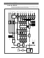
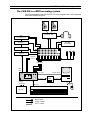
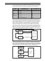
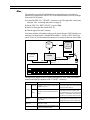
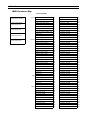
Inside the CBX-D5
The following block diagram shows how the CBX-D5 processes audio data as it travels
from input to output and to the external SCSI hard disks.
DIGITAL
MIXER
4 INPUT
4 BUS
2 SEND
A/D
CONVERTER
DIGITAL
INTERFACE
A/D
CONVERTER
CBX-D5
SCSI
CONTROLLER
PLAY BUFFER
(RAM)
Fs
CONVERTER
PLAY
CONTROL
DEQ
DEQPLAY
CONTROL
Fs
CONVERTER
DEQPLAY
CONTROL
Fs
CONVERTER
DEQPLAY
CONTROL
Fs
CONVERTER
CONTROLLER
DSP
EFFECTS
Fs
CONVERTER
Fs
CONVERTER
Fs
CONVERTER
Fs
CONVERTER
Fs
CONVERTER
Fs
CONVERTER
PLAYBACK
WORDCLOCK
RECORD
WORDCLOCK
RECORD
BUFFER
(RAM)
Y2
INTERFACE
S/PDIF
INTERFACE
AES/EBU
INTERFACE
AES/EBU
INTERFACE
D/A
CONVERTER
D/A
CONVERTER
D/A
CONVERTER
D/A
CONVERTER
ANALOG IN 1
ANALOG IN 2
AES/EBU
IN 1/2
CD/DAT
IN 1/2
Y2 IN 1/2
WORD
CLK IN
WORD
CLK OUT
ANALOG
OUT 1
ANALOG
OUT 2
ANALOG
OUT 3
ANALOG
OUT 4
CD/DAT
OUT 1/2
Y2 OUT 1/2
AES/EBU
OUT 1/2
AES/EBU
OUT 3/4
VOLUME, PITCH
SYNC
EQ
MIDI
MIDI OUT, or
Serial port
MIDI IN, or
TO HOST
HARD
DISK 1
HARD
DISK 2
SCSI
SCSI
SCSI
INPUT MONITOR
SIGNAL PATH
Fs = Sampling Frequency
WORDCLOCK
AUDIO
MIDI
HOST COMPUTER
INPUT LEVEL
METER
S
OUTPUT
LEVEL
METERS

The CBX-D5 in a MIDI recording system 7The CBX-D5 in a MIDI recording system 7The CBX-D5 in a MIDI recording system 7
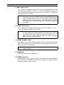
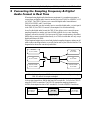
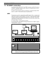
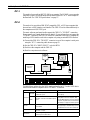
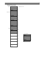
The CBX-D5 in a MIDI recording system
The following diagram shows how the CBX-D5 can be integrated into a MIDI sequencer
based music production system.
MIDI OUT
MIDI
OUT
SERIAL PORT
TO HOST
MIDI IN
MIDI SOUND
SAMPLER
MIDI DRUM MODULE
MIDI TONE
GENERATOR
MIDI
MULTI-EFFECTOR
MASTER
RECORDER
MONITOR AMP
HOST CABLE
AUDIO CABLE
MIDI CABLE
SCSI
HARD
DISK
CD/DAT
YAMAHA
CBX-D5
SCSI
GROUP
OUT x2
LINE IN x4
DIGITAL
TRANSFER

8 Chapter 4 : Controls & Connections8 Chapter 4 : Controls & Connections8 Chapter 4 : Controls & Connections
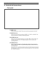
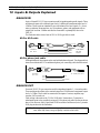
4 Controls & Connections
Front panel
1 POWER switch
Used to turn the power on and off. Press once to switch on, press again to switch off.
2 SOURCE indicators
Indicates the input selected for recording: AES/EBU, Y2, CD/DAT, or ANALOG. The
source input selection is made by the controlling software.
3 REC FREQ indicators
Indicates the selected sampling frequency for recording: 48kHz, 44.1kHz, 32kHz, and
22.05kHz (analog inputs only). The sampling frequency selection is made by the
controlling software.
4 PB FREQ indicators
Indicates the sampling frequency of the digital audio data that is being output by the
CBX-D5: 48kHz, or 44.1kHz. The playback sampling frequency setting is made by the
controlling software.
When the CBX-D5 is used with an external word clock, the digital outputs will operate at
the same frequency as the external word clock and that frequency will not be indicated by
the “PB FREQ” indicators.

Front panel 9Front panel 9Front panel 9
5 INPUT LEVEL meters
Two 12-segment LED bargraphs indicate the level of the incoming digital audio when the
input source is set to AES/EBU, CD/DAT, or Y2 (not affected by the level controls), or the
level of the analog input signals when the input source is set to ANALOG (controlled by
the “ANALOG IN” level controls).
6 OUTPUT LEVEL meters
Four 12-segment LED bargraphs that indicate the output level of channels 1 ~ 4. The
“CLIP” LED indicates an output level of +17dBm.
7 ANALOG IN LEVEL control
Independent level controls for analog input channels 1 and 2. As well as independent level
control, these controls can also be used to balance the left and right channels of a stereo
source connected to the analog inputs.
8 PHONES VOL
Adjusts the volume level of the headphones.
9 PHONES connection
A stereo 6.35 mm (1/4 inch) phone jack used for connecting a pair of stereo headphones.
All four CBX-D5 audio channels can be monitored – channels 1 and 3 appear in the left
speaker and channels 2 and 4 in the right.
NOTE:
Unlike peak meters on analog equipment that light up approximately 3 ~ 6dB
before signal clipping, CLIP LEDs on digital equipment light up when the
signal has actually clipped. Digital audio signal clipping normally produces
unpleasant distortion, pops, and clicks, so care must be taken when setting
the recording level for analog input signals. See “Recording” on page 20 for
more details.
NOTE:
Just like the input level meters, lighting an output level meter’s “CLIP” LED
should be avoided to prevent signal distortion. This situation may occur when
two or more CBX-D5 audio channels are mixed, or if excessive EQ is
applied. The CBX-D5 does not have any output level controls, the output
level is set by the controlling software.
NOTE:
These controls have no effect on the AES/EBU, CD/DAT, and Y2 digital
inputs and outputs.

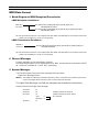
10 Chapter 4 : Controls & Connections10 Chapter 4 : Controls & Connections10 Chapter 4 : Controls & Connections
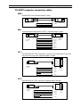
Rear panel
The explanations below are only brief introductions to the CBX-D5’s rear panel
connections. For full details about the inputs and outputs, see “Inputs & Outputs
Explained” on page 26.
1 ANALOG IN 1&2
A pair of female XLR 3-31 type connectors used for inputting analog audio signals. These
are balanced inputs with a nominal input level of +4dBm and a maximum input level of
+22dBm. These could be connected to the outputs of a mixer, synthesizer, drum machine,
etc. Microphones, guitars, and equipment with an output level less than –20dBm must first
be connected to a preamplifier, then to the CBX-D5.
2 ANALOG OUT 1 ~ 4
Four male XLR 3-32 type connectors used for outputting channels 1 ~ 4 as analog audio
signals. These are balanced outputs with a nominal output level of 0dBm and a maximum
output level of +17dBm. These could be connected to the inputs of a mixer, amplifier, tape
recorder, or DAT recorder.
3 AES/EBU IN 1/2
A female XLR 3-31 type connector for inputting AES/EBU format digital audio. Only one
input connection is required for channels 1 and 2 because the AES/EBU format carries two
signals in one connection. These could be used when recording digital audio data from
professional digital audio equipment such as another hard disk recorder, a digital mixer,
digital recorder, or digital VTR.
NOTE:
When the Analog inputs are used unbalanced, the maximum input level is
reduced to +16dBm.

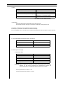
Rear panel 11Rear panel 11Rear panel 11
4 AES/EBU OUT 1/2 & 3/4
Two male XLR 3-32 type connectors for outputting AES/EBU format digital audio.
Channels 1 and 2 are output via “OUT 1/2”, and channels 3 and 4 via “OUT 3/4”. These
could be used to transfer digital audio data from the CBX-D5 to professional digital audio
equipment.
5 CD/DAT IN 1/2
A Phono/RCA jack for inputting CD/DAT format digital audio. Channels 1 and 2 are
carried in the same connection. This connection could be connected to the digital output
of a CD player or DAT recorder and allows digital audio recording without multiple D/A,
A/D audio data conversions. Some MIDI samplers are fitted with this type of connection.
In this case your sound samples could be recorded directly to your CBX-D5 system.
6 CD/DAT OUT 1/2
A Phono/RCA jack for outputting CD/DAT format digital audio. Channels 1 and 2 are
carried in the same connection. This could be connected to the digital input of a DAT
recorder or DCC recorder, and allows digital audio recording without multiple D/A, A/D
audio data conversions.
7 Y2 IN 1/2
An 8-pin DIN socket for inputting Y2 Yamaha format digital audio. As with the AES/EBU
and CD/DAT formats, two audio channels are carried in the same connection. This could
be connected to one of Yamaha’s digital audio products such as a DMR8 Digital
Mixer/Recorder, DMC1000 Digital Mixing Console, DRU8 Digital Recorder, SPX1000
Effect Processor, or the DMP series of Digital Mixers.
8 Y2 OUT 1/2
An 8-pin DIN socket for outputting Y2 Yamaha format digital audio. This could be used
to transfer digital audio data from the CBX-D5 to one of the Yamaha professional digital
audio products listed above. You might not own one of these products yourself, but you
may need to transfer some of your audio data to a recording studio that does.
9 WORD CLK IN/OUT
Two BNC type connectors for inputting and outputting word clock signals. A common
word clock signal is used to synchronize data processing circuits when a number of digital
audio devices are connected together. For a full description of how and when to use these
connections, see “WORD CLK IN/OUT” on page 28.
NOTE:
It is widely known that the weakest links in a digital audio system are the A/D
and D/A converters. For once the audio has been converted into a digital
form, it is immune from all the problems usually associated with analog
equipment such as distortions and noise. Although the effects of multiple
conversions will be hard to spot, even for the best trained ears, it makes sense
that once converted, we try and keep the audio in a digital form by using these
digital I/O connections wherever possible.

12 Chapter 4 : Controls & Connections12 Chapter 4 : Controls & Connections12 Chapter 4 : Controls & Connections
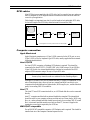
0 MIDI IN
The CBX-D5 receives MIDI control data from the computer via this connection. To
prevent the CBX-D5’s control data being delayed by other MIDI devices, the CBX-D5
should be the first device connected to your computer. Other MIDI devices should then be
connected to the CBX-D5’s MIDI THRU connection.
If your computer’s MIDI interface has two or three MIDI outputs, dedicate one for use
with the CBX-D5.
A MIDI OUT
When the CBX-D5 is being used as a MIDI interface, that is, a direct connection to a
computer via the To Host connection, MIDI data from the computer is output to other
MIDI devices from this connection. Also used for MIDI bulk dump.
B MIDI THRU
MIDI data appearing at the MIDI IN connection is buffered, then output from this
connection. In other words, all MIDI data appearing at the MIDI IN connector is output to
the MIDI THRU connector unaffected by the CBX-D5.
C TO HOST connector
An 8-pin mini DIN connector that allows direct connection to a computer that is running
CBX-D5 supporting software. This can be used when your computer does not have a
MIDI interface, i.e., MIDI input and output connections. See “TO HOST connection” on
page 30 for more details.
D TO HOST select switch
This switch setting depends on the type of computer connected to the “TO HOST”
connector. See “TO HOST connection” on page 30 for full details.
E SCSI connectors
Two 50-way Amphenol type connectors used to connect the CBX-D5 into the SCSI daisy
chain.
F SCSI ID selector
A thumb wheel type switch used to set the SCSI ID number of the CBX-D5. See “SCSI
ID setting” on page 16 for more details.
G Power inlet
A 3-pin power inlet socket. Connect the supplied power cable to this socket, then plug the
other end of the cable into an AC receptacle of the correct type.
NOTE:
Although not usually a problem on a small MIDI system, when more than
three MIDI devices are daisy chained together using MIDI IN and THRU
connections, MIDI data can sometimes be delayed, especially if you transmit
a lot of continuous controller data such as pitch bend or modulation wheel. If
MIDI delays do become a problem, use a MIDI THRU Box to distribute the
MIDI signal to each MIDI device.
NOTE:
The operation of the MIDI IN and MIDI OUT connections varies depending
on the position of the CBX-D5’s Host select switch. See “TO HOST
connection” on page 30 for full details.

Connecting Hard Disk Drives 13Connecting Hard Disk Drives 13Connecting Hard Disk Drives 13
5 Connecting Hard Disk Drives
Before connecting a hard disk drive, read through this chapter to familiarize yourself with
SCSI and how a SCSI daisy chain should be setup.
What type of hard disk?
If you don’t already have a hard disk or are thinking of buying a larger one, see the supplied
card for a listing of recommended disk drives.
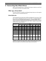
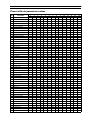
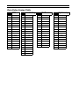
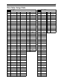
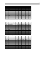
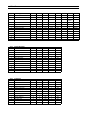
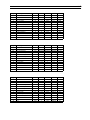
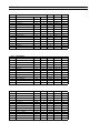
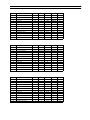
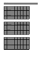
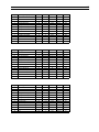
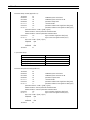
Hard disk size
The following table shows approximate available recording times for various sizes of hard
disk. Available recording times are shown for all of the CBX-D5’s sampling frequencies,
and as you can see, with a higher sampling frequency – less time is available. This is
because using a high sampling frequency produces much more digital data, which means
a bigger sound file. See “Sampling frequency (REC FREQ)” on page 20 for more details
about selecting a sampling frequency.
Although it is doubtful that you will ever buy a hard disk smaller than 40MB for use with
the CBX-D5, the values below 40MB will be useful for checking the remaining record
time that is available on a hard disk that already contains some sound files.
Hard disk / Max.
Sound File Size
Stereo Recording (minutes) Mono Recording (minutes)
22.05
kHz
32
kHz
44.1
kHz
48
kHz
22.05
kHz
32
kHz
44.1
kHz
48
kHz
2000MB (2GB) 380 260 190 174 760 760 380 348
1000MB (1GB) 190 130 95 87 380 380 190 174
660MB 124 85 62 57 248 248 124 114
330MB 62 42 31 28 124 124 62 56
200MB 40 25 20 17 80 50 40 34
100MB 20 13 10 8 40 26 20 16
40MB 8 5 4 3.30 16 10 8 7
20MB 4 3 2 1.42 8 6 4 3.24
10MB 2 1.18 1 51
secs
4 2.36 2 1.42
5MB 1 38
secs
30
secs
26
secs
2 1.16 1 52
secs
1MB 12
secs
7 secs 6 secs 5 secs 24
secs
24
secs
12
secs
10
secs

14 Chapter 5 : Connecting Hard Disk Drives14 Chapter 5 : Connecting Hard Disk Drives14 Chapter 5 : Connecting Hard Disk Drives
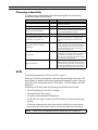
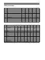
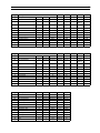
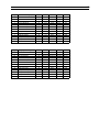
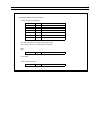
Choosing a hard disk
If you plan to buy a hard disk that is not listed on the supplied card, the following
specifications should be checked first.
SCSI
For an general introduction to SCSI, see “SCSI” on page 3.
Setting up a SCSI daisy chain requires a little more than just making connections. SCSI
devices require ID numbers and the daisy chain must be terminated correctly. These are
explained in the following three sections, “SCSI cables”, “SCSI ID setting”, and “SCSI
termination”.
When using a SCSI daisy chain, the following points should be borne in mind.
• Allocate each device its own SCSI ID number.
• Terminate the SCSI bus correctly.
• Use quality cables and keep the length down.
• Use the little wire clips (or screws) on a SCSI connector to fasten the cable plugs
securely.
• All devices connected in the daisy chain must be switched on to use the system.
• Never switch off, or disconnect a device once the system has been switched on.
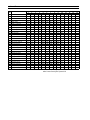
Specification Check Notes
Is it compatible with your computer?
Maybe it is advertised as compatible, or your
dealer recommends it.
Does it have two SCSI connectors? You need two to continue the SCSI daisy chain.
Are the SCSI connectors 25-pin
D-SUB, or 50-way Amphenol?
Macintosh computers are fitted with a 25-pin
D-SUB connector, while most other SCSI devices
have a 50-way Amphenol connector.
Are the SCSI cables supplied? If not, you will need to purchase them separately.
Can the SCSI ID be set from 0 ~ 7? (for
Macintosh you only need 0 ~ 6)
If not, it might clash with another device’s ID, in
which case you may have to rearrange the ID
numbers of some other SCSI devices in the
chain.
Does it have internal or external
termination?
External terminators are normally connected to
the rear of the SCSI device. If the device has an
internal terminator, make sure it can be switched
off so that any device can be positioned at the
end of the SCSI daisy chain.
Access Time?
Measured in milliseconds, this is an indication of
how fast data from different areas of the disk can
be retrieved. The maximum we recommend is
30ms. An access time slower than this may affect
the performance of the CBX-D5.
Data Transfer Rate?
Usually measured in Megabits per second
(Mbit/s), this shows how fast data can be written
to and read from the hard disk. The minimum we
recommend is 16Mbits/s. A transfer rate less than
this may affect the performance of the CBX-D5.
NOTE:
Switch off all your equipment before making any SCSI connections.
Seite wird geladen ...
Seite wird geladen ...
Seite wird geladen ...
Seite wird geladen ...
Seite wird geladen ...
Seite wird geladen ...
Seite wird geladen ...
Seite wird geladen ...
Seite wird geladen ...
Seite wird geladen ...
Seite wird geladen ...
Seite wird geladen ...
Seite wird geladen ...
Seite wird geladen ...
Seite wird geladen ...
Seite wird geladen ...
Seite wird geladen ...
Seite wird geladen ...
Seite wird geladen ...
Seite wird geladen ...
Seite wird geladen ...
Seite wird geladen ...
Seite wird geladen ...
Seite wird geladen ...
Seite wird geladen ...
Seite wird geladen ...
Seite wird geladen ...
Seite wird geladen ...
Seite wird geladen ...
Seite wird geladen ...
Seite wird geladen ...
Seite wird geladen ...
Seite wird geladen ...
Seite wird geladen ...
Seite wird geladen ...
Seite wird geladen ...
Seite wird geladen ...
Seite wird geladen ...
Seite wird geladen ...
Seite wird geladen ...
Seite wird geladen ...
Seite wird geladen ...
Seite wird geladen ...
Seite wird geladen ...
Seite wird geladen ...
Seite wird geladen ...
Seite wird geladen ...
Seite wird geladen ...
Seite wird geladen ...
Seite wird geladen ...
Seite wird geladen ...
Seite wird geladen ...
Seite wird geladen ...
Seite wird geladen ...
Seite wird geladen ...
Seite wird geladen ...
-
 1
1
-
 2
2
-
 3
3
-
 4
4
-
 5
5
-
 6
6
-
 7
7
-
 8
8
-
 9
9
-
 10
10
-
 11
11
-
 12
12
-
 13
13
-
 14
14
-
 15
15
-
 16
16
-
 17
17
-
 18
18
-
 19
19
-
 20
20
-
 21
21
-
 22
22
-
 23
23
-
 24
24
-
 25
25
-
 26
26
-
 27
27
-
 28
28
-
 29
29
-
 30
30
-
 31
31
-
 32
32
-
 33
33
-
 34
34
-
 35
35
-
 36
36
-
 37
37
-
 38
38
-
 39
39
-
 40
40
-
 41
41
-
 42
42
-
 43
43
-
 44
44
-
 45
45
-
 46
46
-
 47
47
-
 48
48
-
 49
49
-
 50
50
-
 51
51
-
 52
52
-
 53
53
-
 54
54
-
 55
55
-
 56
56
-
 57
57
-
 58
58
-
 59
59
-
 60
60
-
 61
61
-
 62
62
-
 63
63
-
 64
64
-
 65
65
-
 66
66
-
 67
67
-
 68
68
-
 69
69
-
 70
70
-
 71
71
-
 72
72
-
 73
73
-
 74
74
-
 75
75
-
 76
76


Yamaha CBX-D5 Benutzerhandbuch
- Kategorie
- Digitale Videorecorder (DVR)
- Typ
- Benutzerhandbuch
in anderen Sprachen
- English: Yamaha CBX-D5 User manual
- français: Yamaha CBX-D5 Manuel utilisateur
- español: Yamaha CBX-D5 Manual de usuario
- italiano: Yamaha CBX-D5 Manuale utente
- русский: Yamaha CBX-D5 Руководство пользователя
- Nederlands: Yamaha CBX-D5 Handleiding
- português: Yamaha CBX-D5 Manual do usuário
- dansk: Yamaha CBX-D5 Brugermanual
- polski: Yamaha CBX-D5 Instrukcja obsługi
- čeština: Yamaha CBX-D5 Uživatelský manuál
- svenska: Yamaha CBX-D5 Användarmanual
- Türkçe: Yamaha CBX-D5 Kullanım kılavuzu
- suomi: Yamaha CBX-D5 Ohjekirja
- română: Yamaha CBX-D5 Manual de utilizare
Verwandte Artikel
-
Yamaha CBX-D5 Bedienungsanleitung
-
-
-
-
-
-
-
-
-
