Thermaltake - Core V21 Benutzerhandbuch
- Kategorie
- Computergehäuse
- Typ
- Benutzerhandbuch
Dieses Handbuch eignet sich auch für
Seite wird geladen ...
Seite wird geladen ...

<185 mm
<350 mm
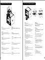
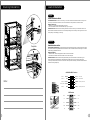
CPU Cooler Height Limitation VGA ( Add-on card) Length Limitation
3 4
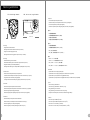
Warning and Notice
Warning!!
- Height limit for the CPU heatsink:
The height limit for the CPU heatsink is 185 mm (7.3 inches).
- Length limit for the VGA (graphics card):
The length limit for the VGA (graphics card) is 350 mm (13.8 inches).
Warnung!!
- Höhenbeschränkung für CPU-Kühler:
Die Höhenbeschränkung für den CPU-Kühler liegt bei 185 mm (7,3 Zoll).
- Längenbeschränkung für die VGA (Grafikkarte):
Die Längenbeschränkung für die VGA (Grafikkarte) beträgt 350 mm (13.8 Zoll).
Avertissement !
- Hauteur limite du dissipateur thermique du processeur :
La hauteur limite du dissipateur thermique du processeur est de 185 mm (7,3 pouces).
- Longueur limite de la carte VGA (carte graphique) :
La longueur limite de la carte VGA (carte graphique) est de 350 mm (13.8 pouces).
Precaución
- Límite de altura para el disipador de calor de la CPU:
El límite de altura para el disipador de calor de la CPU es de 185 mm (7,3 pulgadas).
- Límite de longitud para la tarjeta gráfica (VGA):
El límite de longitud para la tarjeta gráfica (VGA) en de 350 mm (13.8 pulgadas).
Attenzione!
- Limite di altezza per il dissipatore di calore della CPU:
Il limite di altezza per il dissipatore di calore della CPU è 185 mm (7,3’’).
- Limite di lunghezza per la VGA (schede grafiche):
Il limite di lunghezza per la VGA (scheda grafica) è 350 mm (13.8’’).
Atenção!!
- Limite de altura para o dissipador do CPU:
O limite de altura para o dissipador do CPU é 185 mm (7,3 polegadas).
- Limite de comprimento para VGA (placa gráfica):
O limite de comprimento para VGA (placa gráfica) é 350 mm (13.8 polegadas).
警告!!
- CPU散熱器的高度限制:
CPU散熱器的高度限制為185mm(7.3英吋)。
- VGA(顯示卡)的長度限制:
VGA(顯示卡)的長度限制為350mm(13.8英吋)。
警告!!
- CPU散热器的高度限制:
CPU散热器的高度限制为185mm(7.3英寸)。
- VGA(显卡)的长度限制:
VGA(显卡)的长度限制为350mm(13.8英寸)。
警告
- CPUヒートシンクの高さ制限:
CPUヒートシンクの高さ制限は185 mmです。
- VGA(グラフィックスカード)の長さ制限:
VGA(グラフィックスカード)の長さ制限は350 mmです。
Внимание!
- Ограничение по высоте для радиатора ЦП.
Ограничение по высоте для радиатора ЦП составляет 185 мм (7,3 дюйма).
- Ограничение по длине для платы VGA (графическая плата).
Ограничение по длине для платы VGA (графическая плата) составляет 350 мм (13.8 дюйма).
Uyarı!!
- CPU ısı alıcısı için yükseklik sınırı:
CPU ısı alıcısı için yükseklik sınırı 185 mm’dir (7,3 inç).
- VGA (grafik kartı) için uzunluk sınırı:
VGA (grafik kartı) için uzunluk sınırı 350 mm’dir (13.8 inç).
- Kasaya üst ön fanı takıyorsanız, lütfen ilk 5,25” bölmesine aygıt takmayın.
คำเตือน!!
- ขีดจำกัดความสูงสำหรับฮีตซิงก์ของ CPU:
ขีดจำกัดความสูงสำหรับฮีตซิงก์ของ CPU คือ 185 มม. (7.3 นิ้ว)
- ขีดจำกัดความยาวสำหรับ VGA (การ์ดแสดงผล):
ขีดจำกัดความยาวสำหรับ VGA (การ์ดแสดงผล) คือ 350 มม. (13.8 นิ้ว)
藍色線條為尺寸標示,請勿印刷上去!
14/09 /3 0 A
發稿日期
版本
CHECK
125 mm
產品料號
CA-1D 5 - 00S1WN- 0 0 C o re V21
說明書
產品名稱
印刷項目
騎馬釘24
10 5g
雙銅
單色 無無
其他 特殊 處理 效果表面 處理
2
厚度(g/m )
裝訂 方式 材質頁數 印刷 色彩
規格 樣式
整本
DESIGN
peipei
(14/09/30)
Mike.Lin
(14/09/30)
刀模線
176 mm

5
6
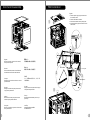
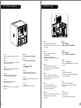
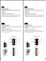
Side Panel Disassembly
PSU Installation
English /
Remove the screws on the back of the chassis,
and open the side panel.
Deutsch /
Entfernen Sie die Schrauben auf der Rückseite
des Gehäuses und öffnen Sie das Seitenteil.
Français /
Enlevez les vis à l’arrière du châssis et ouvrez le
panneau latéral.
Español /
Extraiga los tornillos de la parte posterior de la
caja y abra el panel lateral.
Italiano /
Rimuovere le viti sulla parte posteriore dello
chassis e aprire il pannello laterale.
Português/
Remova os parafusos na parte de trás da caixa e
abra o painel lateral.
繁體中文 /
移除機殼後方螺絲,將側窗打開。
日本語 /
シャーシ背面のねじを取り外し、サイドパネ
ルを開きます。
Русский /
Открутите винты на задней стенке корпуса
и откройте боковую панель.
简体中文 /
卸除机壳后方螺丝,将侧窗打开。
Türkçe /
Kasanın arkasındaki vidaları çıkarın ve yan
paneli açın.
ภาษาไทย /
ถอดสกรูที่ด้านหลังของแชสซีส์
แล้วเปิดแผงด้านข้าง
English /
1. Place the power supply in proper location and
secure it with screws.
2. Place the PSU rubber on bracket.
3. Secure bracket with the case by locking hook.
4. Install the bracket in proper location and secure
it with screws.
PSU rubber
locking hook
hole
1
2
3
4
5
藍色線條為尺寸標示,請勿印刷上去!
14/09 /3 0 A
發稿日期
版本
CHECK
125 mm
產品料號
CA-1D 5 - 00S1WN- 0 0 C o re V21
說明書
產品名稱
印刷項目
騎馬釘24
10 5g
雙銅
單色 無無
其他 特殊 處理 效果表面 處理
2
厚度(g/m )
裝訂 方式 材質頁數 印刷 色彩
規格 樣式
整本
DESIGN
peipei
(14/09/30)
Mike.Lin
(14/09/30)
刀模線
176 mm

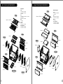
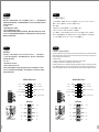
Motherboard Installation
7 8
English /
Install the motherboard in proper location and
secure it with screws.
Deutsch /
Installieren Sie die Hauptplatine in ihrer
vorgesehenen Position und sichern Sie sie mit
Schrauben.
Français /
Installez la carte mère dans l'endroit approprié et
sécurisez-la avec des vis.
Español /
Instale la placa madre en la ubicación adecuada y
asegúrela con tornillos.
Italiano /
Installare la scheda madre nella posizione
appropriata e fissarla con le viti.
Português/
Instale a motherboard no local adequado e aparafuse.
繁體中文 /
將主機板放置在合適的位置並用零件包中之螺絲
固定。
日本語 /
マザーボードを適切な場所に取り付け、ねじで固定
します。
Русский /
Установите материнскую плату в надлежащее
место и закрепите ее винтами.
简体中文 /
在合适的位置安装主板并以螺丝安全固定。
Türkçe /
Ana kartı uygun konuma takın ve vidalarla
sabitleyin.
ภาษาไทย /
ติดตั้งเมนบอร์ดในตำแหน่งที่เหมาะสมแล้วขันสกรู
ยึดให้แน่น
3.5" & 2.5" HDD Installation
English / 繁體中文 /
1. Pull the HDD tray out. 1. 將硬碟托盤取出
2. Place the 2.5” or 3.5” hard drive on the tray and 2. 將2.5”或3.5”硬碟放置在硬碟托盤上,用螺絲固定
secure it with screws. 硬碟
3. Slide the HDD tray back to the HDD cage. 3. 將硬碟托盤放回硬碟磁架中
Deutsch / 简体中文 /
1. Ziehen Sie den HD-Schacht heraus. 1. 将硬盘托盘取出
2. Montieren Sie die 2,5 oder 3,5 Zoll Festplatte im 2. 将2.5”或3.5”硬盘放置在硬盘托盘上,用螺丝固定
Schacht und sichern Sie sie mit Schrauben. 硬盘
3. Schieben Sie den Schacht wieder in den 3. 将硬盘托盘放回硬盘磁架中
Festplattenkäfig.
日本語 /
Français /
1. HDDトレイを引き出して外します。
1. Enlevez le boîtier du disque dur.
2. 2.5インチHDD、SSD もしくは 3.5インチHDD
2. Placez le disque dur de 2,5” ou de 3,5” dans le
ドライブをトレイにネジで固定します。
boîtier et fixez-le avec des vis.
3. HDDトレイをHDDケージに戻します。
3. Refaites glisser le boîtier du disque dur dans la
cage de disques durs.
Русский /
1. Вытяните лоток для жестких дисков.
Español /
2. Установите 2,5- или 3,5-дюймовый жесткий
1. Extraiga la bandeja del disco duro.
диск в лоток и закрепите его винтами.
2. Coloque el disco duro de 2’5 ó 3’5” en la
3. Установите лоток для жестких дисков
bandeja y fíjelo con los tornillos.
обратно в каркас.
3. Vuelva a meter la bandeja del disco duro en su
hueco.
Türkçe /
1. HDD tepsisini dışarı çekin.
Italiano /
2. 2,5” veya 3,5” sabit disk sürücüsünü tepsinin
1. Estrarre il vano HDD.
üzerine yerleştirin ve vidalarla sabitleyin.
2. Posizionare il disco fisso da 2,5” o 3,5” nel vano
3. HDD tepsisini HDD kafesine geri yerleştirin.
e fissarlo con le viti.
3. Fare scorrere l’HDD indietro verso la struttura a
ภาษาไทย /
gabbia HDD.
1. ดึงถาด HDD ออกมา
2. วางฮาร์ดไดร์ฟขนาด 2.5” หรือ 3.5”
Português /
ลงบนถาดแล้วขันสกรูยึดให้แน่น
1. Puxe a bandeja do disco rígido para fora.
3. เลื่อนถาด HDD กลับเข้าในโครง HDD
2. Coloque o disco rígido de 2,5” ou 3,5” na
bandeja e fixe com parafusos.
3. Deslize a bandeja do disco rígido de volta para
a caixa do disco rígido.
3.5" HDD
2.5" HDD
藍色線條為尺寸標示,請勿印刷上去!
14/09 /3 0 A
發稿日期
版本
CHECK
125 mm
產品料號
CA-1D 5 - 00S1WN- 0 0 C o re V21
說明書
產品名稱
印刷項目
騎馬釘24
10 5g
雙銅
單色 無無
其他 特殊 處理 效果表面 處理
2
厚度(g/m )
裝訂 方式 材質頁數 印刷 色彩
規格 樣式
整本
DESIGN
peipei
(14/09/30)
Mike.Lin
(14/09/30)
刀模線
176 mm
Seite wird geladen ...
Seite wird geladen ...
Seite wird geladen ...

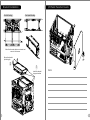
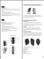
Leads Installation
Leads Installation Guide
Case LED Connection / On the front of the case, you can find some LEDs and switch leads. Please consult your user
manual of your motherboard manufacturer, then connect these leads to the panel header on the motherboard.
USB 3.0 connection /
1. Make sure your motherboard supports USB 3.0 connection.
2. Connect the USB 3.0 cable to the available USB 3.0 port on your computer.
Audio Connection / Please refer to the following illustration of Audio connector and your motherboard user manual.
Please select the motherboard which used AC’97 or HD Audio(Azalia),(be aware of that your audio supports AC’97 or HD
Audio (Azalia)) or it will damage your device(s).
Anschlüsse herstellen
Gehäuse-LED-Verbindungen / Auf der Gehäusevorderseite finden Sie einige LEDs und Verbindungen. Bitte nehmen
Sie die Gebrauchsanweisung Ihres Motherboard Herstellers zur Hilfe und schließen Sie diese Verbindungen an die Panel
Header Belegung des Motherboards an.
USB 3.0 Anschluss /
1. Stellen Sie sicher, dass Ihre Hauptplatine den USB 3.0 Anschluss unterstützt.
2. Verbinden Sie das USB 3.0 Kabel mit dem USB 3.0 Port auf Ihrem Computer.
Audio Anschlüsse / Bitte beachten Sie die folgende Abbildung der Audio Anschlüsse und die Anweisung in der
Gebrauchsanweisung Ihres Motherboards. Bitte wählen Sie das Motherboard, das AC’97 oder HD Audio(Azalia)
verwendet, (achten Sie darauf, dass Ihr Audio AC’97 bzw. HD Audio (Azalia unterstützt)). Andernfalls entstehen schwere
Schäden an Ihrem(n) Gerät(en)!!!
USB 3.0 Connection
PRESENCE#
BLACK
SENSE1_RETURN
AUD GND
SENSE2_RETURN
YELLOW
BROWN
RED
PORT1 R
PORT2 R
PORT1 L
BLUE
PORT2 L
SENSE_SEND
KEY
PURPLE
GREEN
ORANGE
BLACK
AUDIO HD AUDIO Function
N.C KEY
RED2
WHITE2
GREEN2
BLACK2
RED1
WHITE1
GREEN1
BLACK1
USB F unction
VCC1
D1-
D1+
GND
NC
VCC2
D2-
D2+
GND
KEY
English
Deutsch
Stacking Installation
Complete
2
Note:
15
16
藍色線條為尺寸標示,請勿印刷上去!
14/09 /3 0 A
發稿日期
版本
CHECK
125 mm
產品料號
CA-1D 5 - 00S1WN- 0 0 C o re V21
說明書
產品名稱
印刷項目
騎馬釘24
10 5g
雙銅
單色 無無
其他 特殊 處理 效果表面 處理
2
厚度(g/m )
裝訂 方式 材質頁數 印刷 色彩
規格 樣式
整本
DESIGN
peipei
(14/09/30)
Mike.Lin
(14/09/30)
刀模線
176 mm
Seite wird geladen ...
Seite wird geladen ...
Seite wird geladen ...
-
 1
1
-
 2
2
-
 3
3
-
 4
4
-
 5
5
-
 6
6
-
 7
7
-
 8
8
-
 9
9
-
 10
10
-
 11
11
-
 12
12


Thermaltake - Core V21 Benutzerhandbuch
- Kategorie
- Computergehäuse
- Typ
- Benutzerhandbuch
- Dieses Handbuch eignet sich auch für
in anderen Sprachen
- English: Thermaltake - Core V21 User manual
- français: Thermaltake - Core V21 Manuel utilisateur
- español: Thermaltake - Core V21 Manual de usuario
- italiano: Thermaltake - Core V21 Manuale utente
- русский: Thermaltake - Core V21 Руководство пользователя
- português: Thermaltake - Core V21 Manual do usuário
- 日本語: Thermaltake - Core V21 ユーザーマニュアル
- Türkçe: Thermaltake - Core V21 Kullanım kılavuzu
Verwandte Artikel
-
Thermaltake Core V21 Benutzerhandbuch
-
-
Thermaltake View 51 TG Benutzerhandbuch
-
-
-
Thermaltake Versa H24 Benutzerhandbuch
-
-
-
Thermaltake Core X1 Benutzerhandbuch
-