CARLO GAVAZZI
Automation Components
Carlo Gavazzi Controls SpA,
Via Safforze, 8 - 32100
Belluno (Italy)
Tel. +39 0437 355811,
Fax +39 0437 355880
VMU-P EM IM ML 8021341 071013
VMU-P EM
ENGLISH
LED RGB FUNCTION.ON steady light: the module is power supplied and there
is no communication on the auxiliary bus. Green: the power supply is ON. White: the unit
is enabled by VMU-M module for data reading and displaying. Yellow (blinking light): the
communication on the auxiliary bus is working.
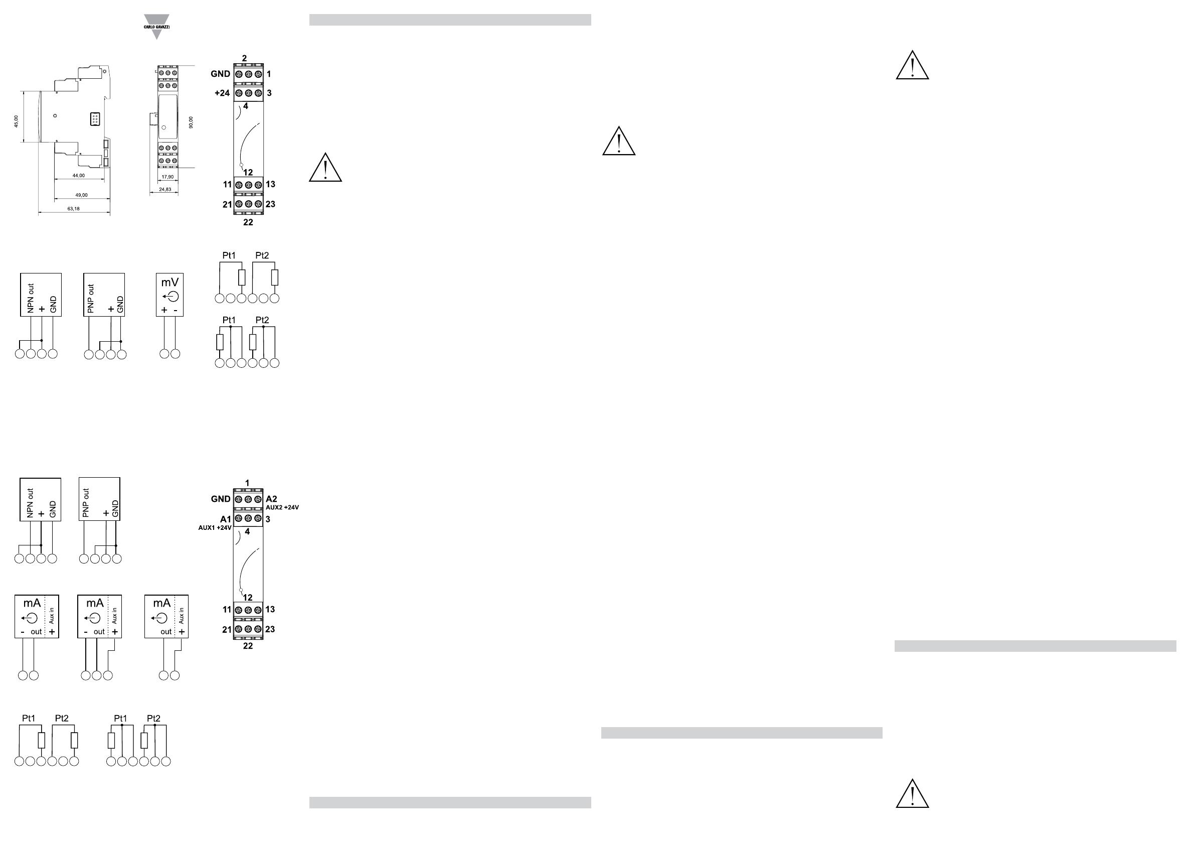
WIRING DIAGRAMS. [1] Pulse rate, NPN output. [2] Pulse rate, PNP output.
[3] Analogue input, mV. [4] Temperature input, Pt1=cell and Pt2=air, 3 wires connec-
tions. [5] Temperature input, Pt1=cell and Pt2=air, 2 wires connections. [6] Pulse rate,
NPN output. [7] Pulse rate, PNP output. [8] [9] [10] Analogue input, mA (2 and 3 wire
connections). [11] Temperature input, Pt1=cell and Pt2=air, 2 wires connections. [12]
Temperature input, Pt1=cell and Pt2=air, 3 wires connections.
SAFETY PRECAUTIONS
Read carefully the instruction manual. If the instrument is used in a manner
not specied by the producer, the protection provided by the instrument may
be impaired. Maintenance: make sure that the connections are correctly car-
ried out in order to avoid any malfunctioning or damage to the instrument. To
keep the instrument clean, use a slightly damp cloth; do not use any abrasives or sol-
vents. We recommend to disconnect the instrument before cleaning it.
TECHNICAL SPECIFICATIONS
Accuracy (@25°C ±5°C, R.H. ≥60%). Temperature See “Temperature input charac-
teristics”. Irradiation from 0 to 120mV: ±(0.5%RDG). Wind speed from 0 to 1000Hz:
±(0.01%RDG). Temperature drift ≤200ppm/°C. Variables format instantaneous vari-
ables 4 DGT (Temperature, solar irradiation and wind speed). Resolution 0.1°C/0.1°F;
1W/m2, 1W/ft2; 0.1m/s, 0.1ft/s. Temperature probe inputs. Number of inputs 2. Tem-
perature probe Pt100, Pt1000. Number of wires up to 3-wire connection. Wire compen-
sation up to 10Ω. Accuracy (Display + RS485) see table “Temperature input characteris-
tics” in the relevant data sheet. Temperature drift ±150ppm. Engineering unit selectable
°C or °F. Irradiation sensor inputs number of inputs 1. Range 0 to 120mVDC. Accuracy
(@25°C ±5°C, R.H. ≤60%) ±(0.2%RDG+1DGT) 0% to 25% FS; (Display + RS485)
±(0.1%RDG+1DGT) 25% to 120% FS. Temperature drift ±150ppm. Scaling factor oper-
ating mode, dual scale: - Input: programmable range from 0 to 999.9 (mVDC) - Display:
programmable range from 0.000 to 9.999 (kW/m2, kW/ft2). Decimal point position xed.
Impedance > 30KΩ. Overload continuous 10VDC (measurement available up to 1V on
both display and communication bus). For 1s 20VDC. Wind speed sensor inputs number
of inputs 1. Range 0 to 1000Hz max, duty cycle 50%. Accuracy @25°C ±5°C, R.H.
≤60%) (Display + RS485) ±(0.02%RDG+1DGT) 0% to 25% FS; ±(0.01%RDG+1DGT)
25% to 110% FS. Temperature drift ±150ppm. Scaling factor operating mode dual
scale: - Input: programmable range from 0 to 999.9 (Hz) - Display: programmable range
from 0.1 to 299.9 (m/s, ft/s). Decimal point position xed. Operating input: 2.5Vpeak to
9Vpeak/5mApeak to 35mApeak, duty cycle 50%; Impedence: 220Ω. Contact measuring
voltage 10 to 50VDC. Contact measuring current <10mA. Contact resistance ≤100Ω
closed contact; ≥500kΩ open contact. Overload continuous 10VDC (measurement
available up to 1V on both display and communication bus) for 1s 20VDC. Insulation,
see “Insulation between inputs and outputs” in the relevant data sheet. Operating tem-
perature -25 to +55°C (-13°F to 131°F) (R.H. from 0 to < 90% non-condensing @ 40°C).
Storage temperature -30 to +70°C (-22°F to 140°F) (R.H. < 90% non-condensing @
40°C). Over voltage category Cat. III (IEC 60664, EN60664). For inputs from string:
equivalent to Cat. I, reinforced insulation. Dielectric strength 4000 VAC RMS for 1 min-
ute. Noise rejection CMRR 100 dB, 45 to 65 Hz. EMC (Immunity) according to EN61000-
6-2. Electrostatic discharges EN61000-4-2: 8kV air discharge, 4kV contact; Immunity to
irradiated electromagnetic elds EN61000-4-3 : 10V/m from 80 to 3000MHz; Immunity
to Burst EN61000-4-4: 4kV on power lines, 2kV on signal lines; Immunity to conducted
disturbances EN61000-4-6: 10V from 150KHz to 80MHz; Surge EN61000-4-5: 500V on
power supply; 4kV on string inputs. EMC (Emission) according to EN61000-6-3. Radio
frequency suppression according to CISPR 22. Standard compliance safety IEC60664,
IEC61010-1 EN60664, EN61010-1. Approvals CE, cULus Listed. Housing dimensions
(WxHxD) 17.5 x 90 x 67 mm. Material Noryl, self-extinguishing: UL 94 V-0. Mounting
DIN-rail. Protection degree Front IP40. Screw terminals IP20. Connections Screw-type
cable cross-section area 1.5 mm2 max. Min./Max. screws tightening torque: 0.4 Nm / 0.8
Nm. Screw terminal purposes 1.5 mm2 3+3 screw terminals used for two temperature
probes 2 screw terminals used for wind speed sensor 2 screw terminals used for solar
irradiation sensor. Weight approx. 100 g (packing included). Power supply self-power
supplied through the communication bus. Power consumption ≤0,7W.
UL508 NOTES: Max. Surrounding Air of 40°C/104°F. Use 60/140°F or 75°C/167°F
copper (CU) conductor and wire size No. 30-12 AWG, stranded or solid for auxiliary and
power supply connections. Use 60/140°F or 75°C/167°F copper (CU) conductor and
wire size No. 14-8 AWG, stranded or solid for 600V-16A input connections. Terminal
tightening torque of 0.4Nm for auxiliary connection. Terminal tightening torque of 1.1Nm
for 600V input connections with AWG8 wire, 0.5 Nm for smaller sizes. Open Type De-
vice.
ITALIANO
FUNZIONE LED RGB MULTICOLORE FRONTALE. Luce accesa ssa:
il modulo è alimentato e non c’è comunicazione sul bus ausiliario. Verde: alimentazione
[1]
3 4 24 G
3 4 24 G
11 13 23 21
11 12 13 21 22 23
1 G
3 4 A1 G
3 4 A1 G
1 A2G 1 A2
11 13 21 23
11 12 13 21 22 23
G 1
[2] [3]
[4]
[5]
VMU-P EM 2TIW
VMU-P EM 2TCW
[6] [7]
[8] [9] [10]
[11] [12]
presente. Bianco: l’unità è abilita dal modulo VMU-M per la lettura e visualizzazione dati.
Giallo (luce lampeggiante): c’è comunicazione sul bus asiliario.
COLLEGAMENTI ELETTRICI [1] Ingresso impulsi, uscita NPN. [2] Ingresso
impulsi, uscita PNP. [3] Ingresso analogico, mV [4] Ingresso in temperatura, Pt1=cella
e Pt2=aria, collegamento 3 li. [5] Ingresso in temperatura, Pt1=cella e Pt2=aria, col-
legamento 2 li. [6] Ingresso impulsi, uscita NPN. [7] Ingresso impulsi, uscita PNP. [8]
[9] [10] Ingresso analogico, mA (connessione a 2 e 3 li). [11] Ingresso in temperatu-
ra, Pt1=cella e Pt2=aria, collegamento 2 li. [12] Ingresso in temperatura, Pt1=cella e
Pt2=aria, collegamento 3 li.
NORME DI SICUREZZA
Leggere attentamente il manuale istruzioni. Qualora l’apparecchio venisse
adoperato in un modo non specicato dal costruttore, la protezione prevista
dall’apparecchio potrebbe essere compromessa. Manutenzione: assicurarsi
che i collegamenti siano effettuati correttamente al ne di evitare qualsiasi
malfunzionamento o danneggiamento dello strumento. Per mantenere pulito lo strumen-
to usare un panno leggermente inumidito; non usare abrasivi o solventi. Si consiglia di
scollegare lo strumento prima di pulirlo.
CARATTERISTICHE TECNICHE
Precisione (@25°C ±5°C, U.R. ≤60%). Temperatura Vedere “Caratteristiche degli in-
gressi in temperatura”. Irraggiamento da 0 a 120mV: ±(0,5%RDG). Wind speed da 0
a 1000Hz: ±(0,01%RDG). Deriva termica ≤200ppm/°C. Formato delle variabili variabili
istantanee 4 DGT (Temperatura, irragiamento solare e velocità del vento). Risoluzione
0,1°C/0,1°F; 1W/m2, 1W/ft2; 0,1m/s, 0,1ft/s. Ingressi sonde di temperatura. Numero
ingressi 2. Sonde Pt100, Pt1000. Numeero di li: connessione no a 3 li. Compensa-
zione li no a 10Ω. Precisione (Display + RS485) Vedere “caratteristiche degli ingressi
in temperatura” nel relativo data sheet. Deriva termica ±150ppm. Unità ingegneristica
selezionabile °C o °F. Isolamento vedere la tabella “Isolamento tra ingressi ed usci-
te”. Ingresso sensore d’irragiamento numero ingressi 1. Portata da 0 a 120mVCC.
Precisione @25°C ±5°C, U.R. ≤60% ±(0,2%RDG+1DGT) 0% a 25% FS; (Display +
RS485) ±(0,1%RDG+1DGT) 25% a 120% FS. Deriva termica ±150ppm Fattore di scala
Modo operativo duplice scala: - Ingresso: portata programmabile da 0 a 999,9 (mVCC)
- Display: portata programmabile da 0,000 a 9,999 (kW/m2, kW/ft2) Posizione punto
deci- male sso. Impedenza: > 30KΩ. Sovraccarico continuo 10VCC (misura disponibile
no a 1V su entrambi dispaly e bus di comunicazione). Per 1s 20VCC. Sensore per la
velocità del vento. Numero ingressi, 1. Portata da 0 a 1000Hz max, duty cycle 50%.
Precisione @25°C ±5°C, U.R. ≤60% ±(0,02%RDG+1DGT) da 0% a 25% FS; (Display
+ RS485) ±(0,01%RDG+1DGT) da 25% a 110% FS. Deriva termica ±150ppm. Fattore
di scala modo operativo, Duplice duale: - Ingresso: portata programmabile da 0 a 999.9
(Hz) - Visualizzata: portata programmabile da 0,1 a 299,9 (m/s, ft/s). Posizione punto
decimale sso. Ingresso operativo: 2.5Vpeak to 9Vpeak/5mApeak to 35mApeak, duty
cycle 50%. Impedenza 220Ω. Tensione di lettura contatto da 10 a 50VCC. Corrente di
lettura contatto <10mA. Rersitenza del contatto ≤100Ω contatto chiuso; ≥500kΩ contat-
to aperto. Sovraccarico Continuo 10VCC (misura disponibile no a 1V sul display e sul
bus di comunicazione). Per 1s 20VDC. Isolamento, vedere “Isolamento tra ingressi ed
uscite”. Temperatura di funzionamento. -25 to +55°C (da -13°F a 131°F) (U.R. da 0 a <
90% senza condensa @ 40°C). Temperatura di immaggazzinamento -30 to +70°C (da
-22°F a 140°F) (R.H. < 90% senza condensa @ 40°C). Categoria d’installazione Cat. III
(IEC 60664, EN60664) Per gl’ingressi di stringa: equivalente all Cat. I, isolamento rinfor-
zato. Isolamento (per 1 minuto) Vedere tabella “Isolamento tra ingressi ed uscite”. Rigi-
dità dielettrica 4000 VAC RMS per 1 minuto. Reiezione CMRR 100 dB, da 45 a 65 Hz.
EMC (Immunità) Secondo EN61000-6-2. Scariche elettrostatiche EN61000-4-2: 8kV
scarica in aria, 4kV contatto; Immunità ai campi elettromagnetici irradianti EN61000-4-3:
10V/m da 80 a 3000MHz; Immunità ai transitori veloci EN61000-4-4: 4kV sulle linee di
potenza, 2kV su singole linee; Immunità ai radio disturbi condotti EN61000-4-6: 10V da
150KHz a 80MHz; Immunità ad impulso EN61000-4-5: 500V sull’alimentazione; 4kV
sugli ingressi di stringa. EMC (Emissioni) secondo EN61000-6-3, Emissioni in radiofre-
quenza secondo CISPR 22. Conformità alle norme Sicurezza IEC60664, IEC61010-1
EN60664, EN61010-1. Approvazioni CE, cULus Listed. Custodia: dimensioni 17,5 x 90
x 67 mm. Materiale Noryl, autoestinguenza: UL 94 V-0. Mountaggio a guida DIN. Grado
di protezione Frontale IP40. Connessioni IP20. Connessioni a vite. Sezione del cavo
1,5 mm2 max. Coppia serraggio viti Min./Max.: 0,4 Nm / 0,8 Nm. Utilizzo delle connes-
sioni 1,5 mm2 3+3 morsetti usati per due ingressi di temperatura 2 morsetti usati per il
sensore della velocità del vento 2 morsetti usati per il sensore di irraggiamento. Peso
circa. 100 g (imballo compreso). Alimentazione autoalimentato attraverso il bus locale.
Autoconsumo ≤0,7W.
DEUTSCH
LED-LEUCHTE. FESTLICHT ON: Das Modul wird mit Strom versorgt und es
besteht keine Kommunikation an den Hilfsbus. Grün: Die Stromversorgung steht auf
ON. Weiß: Die Einheit wird vom VMU-M Modul zum Lesen und Anzeigen der Daten
eingeschaltet. Gelb (Blinklicht): Die Kommunikation an den Hilfsbus läuft.
ANSCHLÜSSE. [1] Impulsrate-Eingang, NPN. [2] Impulsrate-Eingang, PNP
[3] Analogeingang, mV. [4] Temperatureingang, Pt1 und Pt2, 3-adriger Anschluss. [5]
Temperatureingang, Pt1 und Pt2, 2-adriger Anschluss. [6] Impulsrate, NPN. [7] Im-
pulsrate, PNP. [8] [9] [10] Analogeingang, mA (2- und 3-adriger Anschluss). [11]
Temperatureingang, Pt1 und Pt2, 2-adriger Anschluss. [12] Temperatureingang, Pt1
und Pt, 3-adriger Anschluss.
SICHERHEITSBESTIMMUNGEN.
Die Betriebsanleitung aufmerksam lesen. Sollte das Gerät nicht gemäss der
Herstellerangaben verwendet werden, könnte der vom Gerät vorgesehene
Schutz beeinträchtigt werden. Wartung: Beachten Sie den korrekten An-
schluss aller Anschlussterminals um eine Beschädigung des Instrumentes zu
vermeiden. Das Gerät mit einem feuchten Tuch reinigen; keine Scheuer- oder Lösemit-
tel verwenden. Das Gerät vor der Reinigung ausschalten.
TECHNISCHE DATEN
Genauigkeit (@25°C ±5°C, R.F. ≤60%). Temperatur siehe „Temperatureingansei-
genschaften“. Analogeingang von 0 bis 120mV: ±(0.5%RDG). Impulsrate-Eingang von
0 bis 1000Hz: ±(0.01%RDG) Temperaturdrift ≤200ppm/°C. Messgrößenfor-
mat momentanmessgrößen 4 stellig (Temperatur, Analogue- und Impulsrate-Eingän-
ge). Temperatur-Resolution 0.1°C/0.1°F. Temperatursondeneingänge Anzahl
der Eingänge 2. Temperatursonde Pt100, Pt1000. Anzahl der Adern Bis zu 3-adrigem
Anschluss aderausgleich Bis zu 10Ω. Genauigkeit (Display + RS485). Siehe Tabelle
„Temperatureingangseigenschaften in dem entsprechenden Datenblatt“. Temperatur-
drift ±150ppm. Technische Einheit °C oder °F wählbar. Analogeingang. Anzahl
der Eingänge 1. Bereich 0 bis 120mVDC Genauigkeit (@25°C ±5°C, R.F. ≤60%)
±(0.2%RDG+1DGT) 0% bis 25% FS; (Display + RS485) ±(0.1%RDG+1DGT) 25%
bis 120% FS. Temperaturdrift ±150ppm. Skalierungsfaktor Betriebsmodus Dualska-
la: Eingang: Programmierbarer Bereich von 0 bis 999,9 (mVDC) - Display: Program-
mierbarer Bereich von 0,000 bis 9999. Dezimalstellenposition: wählbar. Impedanz: >
30KΩ. Überlast Dauer 10VDC (Messung bis zu 1V auf Display- und Kommunikations-
bus verfügbar). Für 1s 20VDC. Impulsrate-Eingang, Anzahl der Eingänge 1. Be-
reich 0 bis max 1000Hz, Arbeitszyklus 50%. Genauigkeit @25°C ±5°C, R.H. ≤60%)
±(0.02%RDG+1DGT) 0% bis 25% FS; (Display + RS485) ±(0.01%RDG+1DGT) 25%
bis 110% FS. Temperaturdrift ±150ppm. Skalierungsfaktor Betriebsmodus Dualskala: -
Eingang: Programmierbarer Bereich von 0 bis 999,9 (Hz) - Display: Programmierbarer
Bereich von 0,1 bis 9999. Dezimalstellenposition: wählbar. Betriebseingang: 2.5VSpitze
bis 9VSpitze / 5mASpitze bis 35mASpitze, Arbeitszyklus 50%. Impedanz 220Ω. Kontakt
für Spannungsmessung 10 bis 50VDC. Kontakt für Strommessung <10mA. Kontaktwi-
derstand ≤100Ω geschlossener Kontakt; ≥500kΩ offener Kontakt. Überlast kontinuier-
lich 10VDC (Messung bis zu 1V an Display- und Kommunikationsbus verfügbar). Für
1s 20VDC. Isolation, siehe Tabelle „Isolation zwischen Ein- und Ausgängen“ in dem
entsprechenden Datenblatt. Betriebstemperatur -25 bis +55°C (-13°F bis 131°F)
(R.F. von 0 bis < 90% nicht kondensierend @ 40°C). Speichertemperatur -30
bis +70°C (-22°F bis 140°F) (R.F. < 90% nicht kondensierend @ 40°C). Überspan-
nungs klasse Kl. III (IEC 60664, EN60664). Dielektrische Stärke 4000 VAC
RMS für 1 Minute. Lärmrückweisung Gleichtaktunterdrückungsverhältnis 100 dB,
45 bis 65 Hz. EMC (Immunität) gemäß EN61000-6-2. Elektrostatische Entladungen
EN61000-4-2: 8kV Luftentladung, 4kV Kontakt; Immunität bei bestrahlten elektromag-
netischen Feldern EN61000-4-3: 10V/m von 80 bis 3000MHz; Immunität bei Bersten
EN61000-4-4: 4kV an Stromleitungen, 2kV an Signalleitungen; Immunität bei Leitungs-
störungen EN61000-4-6: 10V von 150KHz bis 80MHz; Momentanüberstrom EN61000-
4-5: 500V an Stromversorgung. EMC (Emission) gemäß EN61000-6-3. Funkfrequenz-
unterbrechung Gemäß CISPR 22. Standardkonformität Sicherheit IEC60664,
IEC61010-1 EN60664, EN61010-1. Zulassungen CE, cULus Listed. Gehäuse
Abmessungen (LxHxT) 17.5 (+0.5 -0) x 90 x 67 mm. Material Noryl, selbstlöschend:
UL 94 V-0. Montage DIN-Rail. Schutzgrad Vorderseite IP40 Schraubenklemmen
IP20. Anschlüsse Schraubentyp Kabelquerschnittsbereich 1,5 mm
2
max Min./Max.
Schraubenanzugsmoment: 0,4 Nm / 0,8 Nm. Schraubenendverschlusszwecke (1.5
mm
2
): 3+3 Schraubenendverschlüsse für zwei Temperatursonden 2; Schraubenend-
verschlüsse für Impulsrate-Eingang; 2 Schraubenendverschlüsse für Analogeingang.
Gewicht Ca. 100 g (inkl. Verpackung). Stromversorgung durch Kommunikationsbus
eigenstromversorgt. Stromverbrauch ≤0,7W.
FRANÇAIS
LED. LUMIÈRE FIXE ALLUMÉE: le module est alimenté et il n’y a pas de
communication sur le bus auxiliaire. Verte: l’alimentation est branchée. Blanche: l’unité
est habilitée à la lecture et à l’afchage de données par le module VMU-M. Jaune (lu-
mière clignotante): la communication sur le bus auxiliaire fonctionne.
CONNEXIONS. [1] Taux d’impulsion, NPN. [2] Taux d’impulsion, PNP. [3] En-
trée analogique, mV. [4] Entrée température, Pt1 et Pt2, 3 ls de raccordement. [5]
Entrée température, Pt1 et Pt2, 2 ls de raccordement. [6] Taux d’impulsion, NPN.
[7] Taux d’impulsion, PNP. [8] [9] [10] Entrée analogique, mA (2 et 3 ls de rac-
cordement). [11] Entrée température, Pt1 et Pt2, 2 ls de raccordement. [12] Entrée
température, Pt1 et Pt2, 3 ls de raccordement.
PRÉCAUTIONS DE SECURITE
Lire attentivement le manuel de l’utilisateur. Si l’appareil est utilisé dans des
conditions différentes de celles spéciées par le fabricant, le niveau de pro-
tection prévu par l’instrument peut être compromis. Entretien: s’assurer que
les connexions sont réalisées correctement dans le but d’éviter toutes fautes
ou endommagements de l’appareil. Pour nettoyer l’instrument, utiliser un chiffon hu-

