
TGR 30-200 N

2
Gebrauchsanweisung 3
DE
Instructions for Use 9
EN
Upute za upotrebu 15
Упaтства за употребa 21
Navodila za uporabo 28
Udhëzime për përdorim 34
HR BIH
SQ
MK
SL
Uputstva za upotrebu 40
SR

3
DE
HINWEISE
Das Gerät kann von Kindern ab 8 Jahren und Personen mit
begrenzten physischen, sinnlichen und psychischen
Fähigkeiten oder mit ungenügend Erfahrungen bzw. Kenntnis
benutzt werden, falls sie dabei kontrolliert werden oder über die
sichere Anwendung des Gerätes belehrt worden sind und dass
sie die eventuelle damit verbundene Gefahr verstehen.
Kinder dürfen mit dem Gerät nicht spielen.
Kinder dürfen das Gerät nicht reinigen oder warten, wenn
sie dabei nicht von einer befähigten Person kontrolliert werden.
Die Installation ist nach den gültigen Vorschriften und nach
Anweisungen des Herstellers auszuführen. Die Installation darf
nur ein fachlich ausgebildeter Installateur ausführen.
Bei geschlossenem Druckanschlusssystem ist am
Zuflussrohr des Warmwasserspeichers unbedingt ein
Sicherheitsventil mit Nenndruck von 0,6 MPa (6 bar), 0,9 MPa
(9 bar) oder 1,0 MPa (10 bar) (siehe das Typenschild)
anzuschließen, damit der Nenndruck im Kessel nicht um mehr
als 0,1 MPa (1 bar) übersteigen kann.
Wasser kann aus der Auslassöffnung des Sicherheitsventils
tropfen, d.h. die Auslassöffnung ist auf Atmosphärendruck zu
öffnen.
Der nach unten gerichtete Auslass des Sicherheitsventils
darf in keiner Frostumgebung installiert werden.
Um einen störungsfreien Betrieb zu gewährleisten, ist das
Sicherheitsventil regelmäßig auf Funktion und Leckage zu
überprüfen und bei Bedarf ist der Kalk zu entfernen.
Zwischen dem Warmwasserbereiter und dem
Sicherheitsventil darf kein Absperrventil eingebaut werden, da
sonst die Funktion des Rückschlagventils verhindert ist!
Bevor Sie den Warmwasserbereiter ans Stromnetz
anschließen, ist er unbedingt mit Wasser zu füllen!
Der Warmwasserbereiter ist mit einer zusätzlichen
Thermosicherung versehen. Bei nicht funktionierendem
Arbeitsthermostat kann die Wassertemperatur im
Warmwasserbereiter im Einklang mit den Sicherheitsnormen bis
zu 130 °C steigen. Bei den Wasserleitungsinstallationen sind

4
DE
deshalb die eventuell aufkommenden Temperaturüberlastungen
unbedingt zu beachten.
Sollten Sie den Warmwasserbereiter vom Stromnetz
trennen, müssen Sie im bei Frostgefahr das Wasser aus dem
Kessel entleeren.
Bitte versuchen Sie nicht, eventuelle Fehler am Gerät selbst
zu beseitigen, wenden Sie sich lieber an den nächsten
bevollmächtigten Kundendienst.
Unsere Produkte bestehen aus den umgebungs- und
gesundheitsfreundlichen Bauteilen. Die entsprechende Bauweise der
Produkte ermöglicht, dass sie am Ende der Lebensdauer einfach
demontiert und rezykliert werden können.
Durch die Rezyklierung der Materialien werden die Menge der Abfälle und
der Bedarf an der Produktion der Grundstoffe (z.B. Metalle) mit enormem
Energieverbrauch und erheblicher Emission der Schadstoffe vermindert.
Folglich werden auch die natürlichen Ressourcen bewahrt, denn die Abfallteile aus
Kunststoff und Metall können in den verschiedenen Produktionsverfahren wieder
verwendet werden.
Für mehr Informationen über das System der Abfallbeseitigung fragen Sie Ihr
Zentrum zur Entsorgung von Abfällen oder den Verkäufer, bei welchem Sie das
Produkt gekauft haben.
Sehr geehrter Kunde, wir danken Ihnen, dass Sie unser Produkt
erworben haben.
Bitte lesen Sie diese Gebrauchsanweisung aufmerksam durch, bevor
Sie den Warmwasserbereiter installieren und in Betrieb nehmen.
Der Warmwasserbereiter ist im Einklang mit den gültigen Standards hergestellt und
amtlich getestet worden. Ebenso wurde auch das Sicherheitszertifikat und das
Zertifikat EMV (elektromagnetische Verträglichkeit) ausgestellt. Die technischen
Eigenschaften sind auf dem zwischen den Anschlussrohren angebrachten
Typenschild angegeben. Reparaturen und Eingriffe in das Gerät dürfen nur von einer
Fachkraft bzw. dem Kundendienst ausgeführt werden.
INSTALLATION
Der Warmwasserbereiter ist möglichst nahe an Abnahmestellen zu installieren. Bei
der Installation in einem Raum mit Badewanne oder Dusche sind unbedingt die
Anforderungen des Standards IEC 60364-7-701 (VDE 0100, Teil 701) zu beachten.
Er ist mittels Wandschrauben mit Nominaldurchmesser von mindestens 8 mm an der
Wand zu befestigen. Er darf nur in senkrechter Position befestigt werden. Bei
Befestigungswänden mit geringerer Tragfähigkeit, muss vom Installateur eine
geeignete Befestigungsart gewählt werden. Um die Magnesiumanode leichter zu
kontrollieren und zu ersetzen, lassen Sie oben zwischen dem Warmwasserspeicher

5
DE
und der Decke genügend Platz (siehe Maß G auf der Skizze der Anschlussmaße).
Wird dies nicht berücksichtigt, muss der Warmwasserspeicher beim beschriebenen
Service von der Wand abmontiert werden.
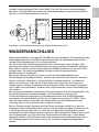
Anschluss- und Montagedimensionen des Warmwasserbereiters [mm]
WASSERANSCHLUSS
Die Wasseristallation muss gemäß DIN1988 durchgefürt werden. Die Anschlüsse des
Warmwasserspeichers sind farblich gekennzeichnet, der Kaltwasserzulauf ist blau
und der Warmwasserzulauf ist rot gekennzeichnet.
Der Anschluss des Warmwasserbereiters kann auf zweierlei Arten erfolgen. Das
geschlossene System (druckfestes System) versorgt mehrere Zapfstellen, während
beim offenen System (druckloses System) die Wasserentnahme nur an einer Stelle
erfolgen kann. Je nach ausgewähltem System sind auch entsprechende
Mischbatterien zu installieren.
Bei einem offenen (druckloses) System muss am Warmwasserbereiter ein
Rückschlagventil eingebaut werden, welches das Auslaufen des Wassers aus dem
Kessel verhindert. Wird das im Gerät befindliche Wasser erwärmt, so dehnt sich
dessen Volumen aus. Dies hat zur Folge, dass das Auslaufrohr der Armatur zu
tropfen beginnt. Starkes Festdrehen der Armatur kann bzw. darf dieses Ausdehnen
und Tropfen nicht verhindern, sondern führt möglicherweise zu einer Beschädigung
der Armatur.
Bei einem geschlossenen (druckfesten) System müssen an den Entnahmestellen die
Druckmischbatterien verwendet werden. Am Zulaufstutzen ist wegen der
Funktionssicherheit unbedingt ein Sicherheitsventil oder eine Sicherheitsgruppe
einzubauen, die das Erhöhen des Drucks im Kessel um mehr als 0,1 MPa (1 bar)
über den Nominalwert verhindert. Die Auslassdüse am Sicherheitsventil muss
unbedingt über einen Auslass für den Luftdruck verfügen.
Bei der Aufheizung des Wassers wird der Druck im Kessel erhöht bis er den am
Sicherheitsventil eingestellten Wert erreicht. Da die Rückleitung des Wassers zurück
in die Wasserleitung verhindert ist, kann es zum Abtropfen des Wassers aus der
Auslassöffnung des Sicherheitsventils kommen. Das abtropfende Wasser kann durch
den Auffangansatz, den Sie unter dem Sicherheitsventil anbringen, in den Ablauf
abgeleitet werden. Das Ablaufrohr unter dem Auslass des Sicherheitsventils muss in
der Richtung gerade nach unten und in einer frostfreien Umgebung angebracht
werden.
A B C D E F G
TGR 30 N 468 275 173 - 454 461 80
TGR 50 N 585 365 200 - 454 461 130
TGR 80 N 790 565 205 - 454 461 180
TGR 100 N 950 715 215 - 454 461 260
TGR 120 N 1090 865 205 - 454 461 260
TGR 150 N 1305 1065 220 - 454 461 260
TGR 200 N 1514 1050 444 800 500 507 260

6
DE
Falls die bereits ausgeführte Installation keine Möglichkeit bietet, das tropfende
Wasser aus dem Sicherheitsventil in den Abfluss zu leiten, kann das Tröpfeln auch
durch das 3 l- Expansionsgefäß verhindert werden. Das Gefäß montieren Sie am
Zulaufrohr des Warmwasserbereiters.
Das richtige Funktionieren des Sicherheitsventils müssen Sie in regelmässigen
Zeitabständen selber überprüfen und nach Bedarf den Kalk entfernen und die
eventuelle Blockade des Ventils beseitigen. Bei einer Prüfung ist durch Verschiebung
des Hebels oder durch Lösen der Ventilmutter (je nach Ventiltyp) der Auslauf aus
dem Sicherheitsventil zu öffnen. Dabei muss aus der Auslaufdüse des Ventils das
Wasser ausfließen, was die einwandfreie Funktion des Ventils bestätigt.
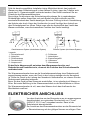
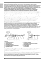
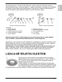
Geschlossenes System (druckfestes System) Offenes System (druckloses System)
Es darf kein Absperrventil zwischen dem Warmwasserbereiter und
Sicherheitsventil installiert sein, da sonst die Funktion des Sicherheitsventils
verhindert wird.
Der Warmwasserbereiter kann an die Haushaltswasserleitung ohne Reduzierventil
angeschlossen werden, wenn der Druck in der Leitung niedriger als der Nenndruck
ist. Sollte der Druck in der Leitung den Nenndruck überschreiten, so müssen Sie das
Reduzierventil unbedingt einbauen.
Bevor Sie das Gerät an das Stromnetz anschließen, ist es unbedingt mit Wasser zu
füllen. Bei erster Befüllung ist der Warmwasserhebel an der Mischbatterie zu öffnen.
Der Warmwasserbereiter ist voll, wenn das Wasser durch das Ausflussrohr der
Mischbatterie ausfliest.
ELEKTRISCHER ANSCHLUSS
Vor dem Anschluss an das Stromnetz muss ein angemessenes
Anschlusskabel von minimalem Durchschnitt von 1,5 mm
2
(H05VV-F 3G 1,5 mm
2
) eingebaut werden. Dazu ist der
Schutzdeckel abzuschrauben.
Der Anschluss des Warmwasserbereiters an das Stromnetz hat
in Übereinstimmung mit den gültigen Normen zu erfolgen. Dem
Legende:
1 - Sicherheitsventil
2 - Ablaufrohr
3 - Rückflussstopp
4 - Druckminderer
5 - Absperrventil
6 - Prüfstutzen
7 - Ablaufsiphon
8 - Expansionsgefäß
H - Kaltwasser
T - Warmwasser

7
DE
Gerät muss eine allpolige Trennvorrichtung vorgeschaltet werden, der sämtliche
Speisepole laut nationalen Installationsvorschriften unterbricht.
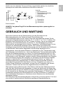
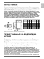
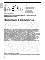
Legende:
1 - Anschlussklemme
2 - Thermostat mit zweipolige
Thermosicherung
3 - Heizkörper
4 - Kontrolleuchte
L - Phasenleiter
N - Neutralleiter
- Schutzleiter
Elektroschaltbild
HINWEIS: Vor jedem Eingriff ist der Warmwasserspeicher spannungsfrei zu
schalten!
GEBRAUCH UND WARTUNG
Nach dem Anschluss an die Wasserleitung und das Stromnetz ist der
Warmwasserbereiter zum Gebrauch bereit. Durch Drehen des
Thermostatdrehknopfes an der unteren Seite des Schutzdeckels können Sie die
gewünschte Wassertemperatur zwischen 10 °C und 65 °C +5 °C/-0 °C wählen. Wir
empfehlen den Drehknopf auf die "eco" Position zu stellen. Das ist die sparsamste
Einstellung; die Wassertemperatur ist etwa 55 °C, die Kalkablagerung und der
Wärmeverlust sind geringer als bei höherer Temperatur. Im Betriebszustand, ist ein
Geräusch im elektrischen Heizkörper hörbar. Die Funktion des elektrischen
Heizkörpers wird durch die Kontrolleuchte gezeigt. An der Stirnseite des Heizkörpers
ist das Bimetall-Thermometer angebracht und die Zeiger bewegen sich im
Uhrzeigersinn, wenn das warme Wasser im Heizkörper ist. Der Thermometer zeigt
die Temperatur am Aufstellort an, durch das Drehen des Thermostatknopfes stellen
Sie aber die Wassertemperatur im unteren Teil des Warmwasserbereiters ein. Die
Folge kann die Temperaturdifferenz zwischen den beiden Anzeigewerten sein. Das
Thermometer ist kein Messgerät, sondern zeigt die Rahmentemperatur des Wassers.
Wenn Heizkörper längere Zeit nicht aktiv ist, verhindern Sie das Einfrieren dessen
Inhalts so, dass Sie den Thermostatdrehknopf auf die Position " " stellen, der
Heizkörper bleibt aber angeschlossen. In dieser Einstellung hält das Gerät bei
minimalem Energieverbrauch das Wasser auf einer Temperatur von etwa 10 °C.
Sollten Sie den Heizkörper ausschalten, müssen Sie bei Frostgefahr das Wasser
auslassen. Danach kann an einer der angeschlossenen Armaturen das
Warmwasserventil geöffnet werden. Das Wasser wird über den Kaltwassereinlauf
oder über das Sicherheitsventil abgelassen, so dass der Hebel oder die Kappe des
Sicherheitsventils wie bei der Kontrolle auf seine einwandfreie Funktion gedreht wird.
Es ist sinnvoll bei der Montage einen speziellen Reduziernippel (T-Stück) oder ein
Auslassventil zwischen dem Sicherheitsventil und dem Zuflussrohr zu installieren.
Das verbleibende Restwasser im Gerät kann durch Abdrehen des Heizflansches
abgelassen werden.
Die Außenseite des Warmwasserbereiters reinigen Sie mit einem weichen Tuch und
einer milden für glatte lackierte Oberflächen geeignete Waschmittellösung.

8
DE
Verwenden Sie keine alkoholhaltigen oder grobe Reinigungsmittel.
Durch die regelmäßigen Servicekontrollen werden einwandfreie Funktion und eine
lange Lebensdauer des Warmwasserbereiters gewährleistet. Die
Durchrostungsgarantie des Kessels gilt nur bei vorgeschriebenen regelmäßigen
Prüfungen der Antikorrosions-Schutzanode auf Abnutzung. Die Zeit zwischen den
einzelnen regelmäßgien Prüfungen darf nicht länger sein als in der Garantierklärung
festgelegt wird. Die Prüfungen sind von einem autorisierten Servicemann
durchzuführen, der die Kontrolle in die Garantieurkunde des Produktes einträgt.
Dabei ist die Antikorrosions-Schutzanode auf Abnutzung zu prüfen und nach Bedarf
der Kalk zu entfernen, der sich je nach Qualität, Menge und Temperatur des
verbrauchten Wassers im Inneren des Warmwasserbereiters bildet. Der
Kundendienst wird Ihnen je nach festgestelltem Zustand auch den Termin für die
nächste Servicekontrolle empfehlen.
Bitte, versuchen Sie nicht, eventuelle Fehler am Gerät selbst zu beseitigen,
wenden Sie sich lieber an den nächsten bevollmächtigten Kundendienst.
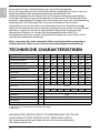
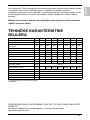
TECHNISCHE CHARAKTERISTIKEN
1) Verordnung der Kommission EU 812/2013; EN 50440
2) EN 50440
WIR BEHALTEN UNS DAS RECHT FÜR ÄNDERUNGEN VOR, DIE DIE
FUNKTIONALITÄT DES GERÄTES NICHT BEEINTRÄCHTIGEN.
Die Gebrauchsanweisungen finden Sie auch auf unseren Webseiten
http://www.gorenje.com.
Typ
TGR 30 N TGR 50 N TGR 80 N TGR 100 N TGR 120 N TGR 150 N TGR 200 N
Angegebenes Lastprofil
S M M L L XL XL
Energieeffizienzklasse
1)
C C C C C C D
Warmwasserbereitungs-
Energieeffizienz (ƞwh)
1)
33,1 36,0 36,0 37,1 37,0 38,0 35,2
[%]
Jährlicher Stromverbrauch
1)
558 1427 1428 2762 2770 4413 4756
[kWh]
Täglicher Stromverbrauch
2)
2,671 6,692 6,698 12,850 12,901 20,401 22,430
[kWh]
Temperatureinstellung des
Thermostats
"eco" "eco" "eco" "eco" "eco" "eco" "eco"
Wert "smart"
0 0 0 0 0 0 0
Volumen
30,4 48,1 73,0 93,4 110,7 139,8 195,4
[l]
Mischwassermenge bei 40 °С V40
2)
- 67 92 131 155 212 274
[l]
Aufwärmezeit von 10 °С bis 65 °С 0:59 1:34 2:20 3:10 3:46 4:42 6:32 [h]
Nenndruck 0,6 (6)
[MPa
(bar)]
Gewicht / voll
15,5/45,5
21/71 27/107 31/131 35/155 41/191 65/265 [kg]
Korrosionsschutz des Kessels emailliert / Mg-Schutzanode
Leistung des elektrischen
Heizkörpers
2000 [W]
Anschlussspannung 230 [V~]
Schutzklasse I
Schutzart (Schutzstufe) IP23

9
EN
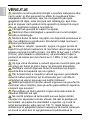
WARNINGS
The appliance may be used by children older than 8 years
old, elderly persons and persons with physical, sensory or
mental disabilities or lacking experience and knowledge, if they
are under supervision or taught about safe use of the appliance
and if they are aware of the potential dangers.
Children should not play with the appliance.
Children should not clean or perform maintenance on the
appliance without supervision.
Installation should be carried out in accordance with the
valid regulations and according to the instructions of the
manufacturer and by qualified staff.
In a closed, pressurised system of installation, it is obligatory
to install a safety valve on the inlet pipe with a rated pressure of
0.6 MPa (6 bar), 0.9 MPa (9 bar) or 1.0 MPa (10 bar) (see the
label), which prevents the elevation of pressure in the boiler by
more than 0.1 MPa (1 bar) above the rated pressure.
Water may drip from the outlet opening of the safety valve,
so the outlet opening should be set to atmospheric pressure.
The outlet of the safety valve should be installed facing
downwards and in a non-freezing area.
To ensure proper functioning of the safety valve, the user
should perform regular controls to remove limescale and make
sure the safety valve is not blocked.
Do not install a stop valve between the water heater and the
safety valve, because it will impair the pressure protection of the
heater!
Before connecting it to the power supply, the water heater
must be filled with water!
The heater is equipped with an additional thermal cut-off for
protection in case of failure of the operating thermostat. In this
case, however, the temperature of the water in the heater can
reach up to 130 °C according to the safety standards. During
the water supply installation, the possibility of temperature
overloads should be taken into account.
If the heater is to be disconnected from the power supply,
please drain any water from the heater to prevent freezing.

10
EN
Please do not try to fix any defects of the water heater on
your own. Call the nearest authorised service provider.
Our products incorporate components that are both environmentally safe
and harmless to health, so they can be disassembled as easily as possible
and recycled once they reach their final life stage.
Recycling of materials reduces the quantity of waste and the need for
production of raw materials (e.g. metals) which requires a substantial
amount of energy and causes release of harmful substances. Recycling procedures
reduce the consumption of natural resources, as the waste parts made of plastic and
metal can be returned to various production processes.
For more information on waste disposal, please visit your waste collection centre or
the store where the product was purchased.
Dear buyer, thank you for purchasing our product.
Prior to the installation and first use of the electric water
heater, please read these instructions carefully.
This water heater has been manufactured in compliance with the relevant standards
and tested by the relevant authorities as indicated by the Safety Certificate and the
Electromagnetic Compatibility Certificate. The technical characteristics of the product
are listed on the label affixed between the inlet and outlet pipes. The installation must
be carried out by qualified staff. All repairs and maintenance work within the water
heater, e.g. lime removal or inspection/replacement of the protective anticorrosion
anode, must be carried out by an authorised maintenance service provider.
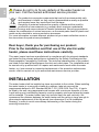
INSTALLATION
The water heater shall be installed as close as possible to the outlets. When installing
the water heater in a room with a bathtub or shower, take into account the
requirements defined in IEC Standard 60364-7-701 (VDE 0100, Part 701). It has to
be fitted to the wall using appropriate wall screws with a minimum diameter of 8 mm.
A wall with a poor load-bearing capacity must be properly reinforced where the heater
will be installed. The water heater may only be fixed upon the wall vertically. We
recommend the distance between the water heater and the ceiling is large enough to
allow simple replacement of the Mg anode (see dimension G in the Installation
Drawing), in order to avoid unnecessary dismounting of the heater during the
servicing intervention.

11
EN
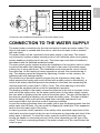
Connection and installation dimensions of the water heater [mm]
CONNECTION TO THE WATER SUPPLY
The water heater connections for the inlet and outlet of water are colour-coded. The
inlet of cold water is marked with blue colour, while the hot water outlet is marked
with red colour.
The water heater can be connected to the water supply in two ways. The closed-
circuit pressure system enables several points of use, while the open-circuit gravity
system enables a single point of use only. The mixer taps must also be installed in
accordance with the selected installation mode.
The open-circuit gravity system requires the installation of a non-return valve in order
to prevent the water from draining out of the tank in the event of the water supply
running dry or being shut down. This installation mode requires the use of a cross-
flow mixer tap. As the heating of water expands its volume, this causes the tap to
drip. The dripping cannot be stopped by tightening it further; on the contrary, the
tightening can only damage the tap.
The closed-circuit pressure system requires the use of pressure mixer taps. For
safety reasons the supply pipe must be fitted with a safety valve or alternatively, a
valve of the safety class that prevents the pressure in the tank from exceeding the
nominal pressure by more than 0.1 MPa (1 bar). The outlet opening on the relief
valve must be equipped with an outlet for atmospheric pressure.
The heating of water in the heater causes the pressure in the tank to increase to the
level set by the safety valve. As the water cannot return to the water supply system,
this can result in dripping from the outlet of the safety valve. The drip can be piped to
the drain by installing a catching unit just below the safety valve. The drain installed
below the safety valve outlet must be piped down vertically and placed in an
environment that is free from the onset of freezing conditions.
In case the existing plumbing does not enable you to pipe the dripping water from the
safety valve into the drain, you can avoid the dripping by installing a 3-litre expansion
tank on the inlet water pipe of the boiler.
In order to provide correct operation of the safety valve, periodical inspections of the
relief valve must be carried out by the user to eliminate any limescale and check if the
safety valve is blocked. To check the valve, open the outlet of the safety valve by
turning the handle or unscrewing the nut of the valve (depending on the type of the
valve). The valve is operating properly if the water comes out of the nozzle when the
outlet is open.
A B C D E F G
TGR 30 N 468 275 173 - 454 461 80
TGR 50 N 585 365 200 - 454 461 130
TGR 80 N 790 565 205 - 454 461 180
TGR 100 N 950 715 215 - 454 461 260
TGR 120 N 1090 865 205 - 454 461 260
TGR 150 N 1305 1065 220 - 454 461 260
TGR 200 N 1514 1050 444 800 500 507 260

12
EN
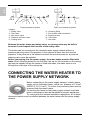
Closed (pressure) system Open (non-pressure) system
Between the water heater and safety valve, no closing valve may be built in
because it could impede the function of the safety valve.
The heater can be connected to the domestic water supply network without a
pressure-reducing valve if the pressure in the network is lower than the nominal
pressure. If the pressure in the network exceeds the nominal pressure, a pressure-
reducing valve must be installed.
Before connecting it to the power supply, the water heater must be filled with
water. When filling the heater for the first time, the tap for the hot water on the mixing
tap must be opened. When the heater is filled with water, the water starts to run
through the outlet pipe of the mixing tap.
CONNECTING THE WATER HEATER TO
THE POWER SUPPLY NETWORK
Before connecting to the power supply network, install a power
supply cord in the water heater, with a min. diameter of 1.5 mm
2
(H05VV-F 3G 1.5 mm
2
). To do this, the protective plate must be
removed from the water heater.
Connecting the heater to the power supply network must take
place in accordance with the standards for electric appliances.
To comply with the national installation regulations, an all poles
disconnect switch must be installed between the water heater and the power supply
network.
Legend:
1 - Safety valve
2 - Test valve
3 - Non-return valve
4 - Pressure reduction valve
5 - Closing valve
6 - Checking fitting
7 - Funnel with outlet connection
8 - Expansion tank
H - Cold water
T - Hot water

13
EN
Legend:
1 - Connection terminal
2 - Thermostat and bipolar thermal cut-out
3 - Electric heating element
4 - Pilot lamp
L - Live conductor
N - Neutral conductor
- Earthing conductor
Electric installation
CAUTION: Before any intervention into the interior of the water heater,
disconnect it from the power supply network!
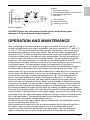
OPERATION AND MAINTENANCE
After connecting to the water and power supply, the heater is ready for use. By
turning the thermostat knob, water temperature can be set between 10 °C and 65 °C
+5 °C/-0 °C. We recommend that the knob be set to the position "eco" ensuring the
most economic operation of the water heater. This way, the water temperature is
maintained at 55 °C while the operation also results in less lime sediment as well as
in less heat losses than is the case at higher temperatures. During the operation of
an electric heater can hear noise in the water heater. The light indicator shows the
operation of the heating element. On the casing of the water heater a bimetal
thermometer is mounted, pointing clockwise (to the right) whenever there is hot water
in the water heater. The thermometer shows the temperature at the place of
installation, while the control knob on the thermostat sets the temperature of water in
the bottom part of the heater. As a result these two temperatures may differ. The
thermometer only gives an approximate temperature of water and is not a measuring
device. When the water heater is not in use for longer periods of time, it should be
protected from freezing by setting the temperature to " ". Do not disconnect the
power. Thus the temperature of water is maintained at about 10 °C. Should you
choose to disconnect the power, the water heater should be thoroughly drained
before the onset of freezing conditions. Water from the heater is drained through the
inlet pipe of the heater. For this purpose, a special fitting (T-fitting) must be mounted
between the relief valve and the heater inlet pipe, or a discharge tap. The heater can
be discharged directly through the relief valve, by rotating the handle or the rotating
valve cap to the same position as for checking the operation. Before discharge, make
sure the heater is disconnected from the power supply, and open the hot water on the
connected mixer tap. After discharging through the inlet pipe, there is still some water
left in the water heater. The remaining water will be discharged after removing the
heating flange, through the heating flange opening.
The external parts of the water heater can be cleaned with a mild detergent solution.
Do not use solvents and abrasives.
With regular service inspections you will ensure faultless functioning and long life of
the heater. Tank corrosion warranty applies only if all the prescribed regular
inspections of the protective anode wear have been made. The period between
regular inspections should not be longer than stated in the warranty certificate.

14
EN
Inspections should be carried out by authorised service providers that will record
each inspection on the warranty statement of the product. Upon inspection the
service provider will inspect the amount of wear on the anti-corrosion anode and, if
necessary, clean the limescale that accumulates depending on the quality, quantity
and temperature of the water inside the heater. The service provider will also
recommend the date for the next inspection depending on the condition of the heater.
Never try to repair any possible faults of the water heater by yourself, but
inform about it the nearest authorised service workshop.
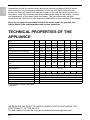
TECHNICAL PROPERTIES OF THE
APPLIANCE
1) EU Regulation 812/2013; EN 50440
2) EN 50440
WE RESERVE THE RIGHT TO MAKE CHANGES THAT DO NOT IMPAIR THE
FUNCTIONALITY OF THE DEVICE.
The user manual can also be found at our website http://www.gorenje.com.
Type
TGR 30 N TGR 50 N TGR 80 N TGR 100 N TGR 120 N TGR 150 N TGR 200 N
Declared load profile
S M M L L XL XL
Energy efficiency class
1)
C C C C C C D
Water heating energy efficiency
(ƞwh)
1)
33,1 36,0 36,0 37,1 37,0 38,0 35,2
[%]
Annual electricity consumption
1)
558 1427 1428 2762 2770 4413 4756
[kWh]
Daily electricity consumption
2)
2,671 6,692 6,698 12,850 12,901 20,401 22,430
[kWh]
Thermostat temperature settings "eco" "eco" "eco" "eco" "eco" "eco" "eco"
Value of "smart"
0 0 0 0 0 0 0
Volume
30,4 48,1 73,0 93,4 110,7 139,8 195,4
[l]
Quantity of mixed water at 40 °С
V40
2)
- 67 92 131 155 212 274
[l]
Heating time from 10 °С to 65 °С 0:59 1:34 2:20 3:10 3:46 4:42 6:32 [h]
Rated pressure 0,6 (6)
[MPa
(bar)]
Weight / Filled with water
15,5/45,5
21/71 27/107 31/131 35/155 41/191 65/265 [kg]
Anti-corrosion of tank enamelled & Mg Anode
Power of electrical heater 2000 [W]
Connection voltage 230 [V~]
Protection class I
Degree of protection IP23

15
HR/BIH
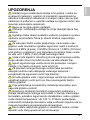
UPOZORENJA
Uređaj mogu koristiti djeca starija od 8 godina i osobe sa
smanjenim tjelesnim, osjetnim ili mentalnim sposobnostima,
odnosno nedovoljnim iskustvom ili znanjem samo ako su pod
nadzorom ili podučeni o uporabi uređaja na siguran način i ako
razumiju potencijalne opasnosti.
Djeca se ne smiju igrati uređajem.
Čišćenja i održavanja uređaja ne smiju obavljati djeca bez
nadzora.
Ugradnju treba obaviti sukladno važećim propisima i prema
uputama proizvođača. Mora ju obaviti stručno osposobljen
monter.
Za zatvoreni tlačni sustav priključenja, na dovodnu cijev
grijalice vode obvezatno ugradite sigurnosni ventil s nazivnim
tlakom 0,6 MPa (6 bara), 0,9 MPa (9 bara) ili 1,0 MPa (10 bara)
(vidi pločicu s natpisom), koji sprječava povećanje tlaka u kotlu
za više od 0,1 MPa (1 bar) iznad nazivnoga tlaka.
Voda može kapati iz odvodnog otvora sigurnosnoga ventila,
stoga odvodni otvor mora biti otvoren na atmosferski tlak.
Ispust sigurnosnoga ventila mora biti postavljen u smjeru
nadolje i na mjestu na kojem neće smrznuti.
Za pravilan rad sigurnosnoga ventila treba periodično
obavljati kontrole radi uklanjanja vodenoga kamenca i
provjeravati da sigurnosni ventil nije blokiran.
Između grijalice vode i sigurnosnoga ventila nije dozvoljeno
ugrađivati zaporni ventil jer bi se time onemogućila tlačna
zaštita grijalice!
Prije priključenja na električne instalacije obvezatno prvo
napunite grijalicu vodom!
Grijalica je dodatnim termičkim osiguračem zaštićena u
slučaju otkazivanja radnoga termostata. U slučaju otkazivanja
termostata, sukladno sigurnosnim standardima, voda u grijalici
može dostići temperaturu i do 130 °C. Prilikom postavljanja
vodovodnih instalacija obvezatno valja uvažavati činjenicu da su
moguća navedena preopterećenja temperature.
Ako budete isključivali grijalicu iz električne mreže, morate
ispustiti vodu zbog opasnosti od smrzavanja.

16
HR/BIH
Molimo: eventualne kvarove na grijalici nemojte popravljati
sami već obavijestite najbliži ovlašteni servis o tome.
Naši su proizvodi opremljeni ekološki besprijekornim i zdravstveno
ispravnim neškodljivim komponentama te su proizvedeni tako da se u svojoj
posljednjoj fazi trajanja mogu što jednostavnije rastaviti i reciklirati.
Reciklažom materijala smanjuju se količine otpada i potreba za
proizvodnjom osnovnih materijala (naprimjer kovine), što iziskuje puno
energije i uzrokuje emisije štetnih tvari. Postupcima reciklaže smanjuje se potrošnja
prirodnih izvora budući da se otpadni dijelovi od plastike i kovine ponovno vraćaju u
različite proizvodne procese.
Za više informacija o sustavu odlaganja otpadaka posjetite lokalni centar za
odlaganje otpadaka ili trgovca kod kojeg ste kupili proizvod.
Poštovani kupci! Zahvaljujemo na povjerenju koje ste nam
ga iskazali kupnjom našega proizvoda.
MOLIMO PRIJE MONTAŽE I PRVE UPORABE POMNO
PROČITAJTE UPUTE ZA MONTAŽU, UPORABU I
ODRŽAVANJE ELEKTRIČNE GRIJALICE VODE.
Grijalica je proizvedena sukladno važećim standardima i službeno je ispitana te su joj
dodijeljeni sigurnosni certifikat i certifikat o elektromagnetskoj kompatibilnosti.
Osnovna tehnička svojstva grijalice navedena su na natpisnoj tablici koja je
nalijepljena između priključnih cijevi. Priključenje grijalice na vodovodnu i električnu
mrežu može obaviti isključivo stručno osposobljena osoba.
Zahvate u njegovu unutrašnjost zbog popravka, uklanjanje vodenoga kamenca te
provjere ili zamjene zaštitne anode protiv korozije obavlja isključivo ovlaštena
servisna služba.
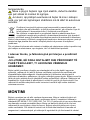
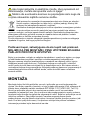
MONTAŽA
Grijalicu montirajte što je moguće bliže potrošačkome mjestu. Ako uređaj za grijanje
ugrađujete u prostor u kojem su kada za kupanje ili tuš, obvezatno morate uzeti u
obzir zahtjeve standarda IEC 60364-7-701 (VDE 0100, Teil 701). Na zid ju pričvrstite
dvаma vijcima za zid, nazivnoga promjera od najmanje 8 mm. Ako je nosivost zida
koji je namijenjen montaži grijalice neodgovarajući, zid treba primjereno ojačati.
Grijalica se smije pričvrstiti na zid isključivo u uspravnome položaju. Zbog lakše
kontrole i zamjene magnezijske anode vam preporučujemo da između vrha uređaja
za grijanje i stropa ostavite dovoljno prostora (pogledaj mjeru G na skici priključnih
mjera). U suprotnom će slučaju pri navedenom servisnom zahvatu biti potrebno
uređaj za grijanje demontirati sa zida.

17
HR/BIH
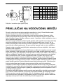
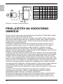
Priključne i montažne mjere grijalice [mm]
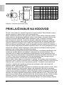
PRIKLJUČAK NA VODOVODNU MREŽU
Dovod i odvod vode na cijevima grijalice označeni su u boji. Dovod hladne vode
označen je plavom a odvod tople vode crvenom bojom.
Grijalicu možete priključiti na vodovodnu mrežu na dva načina. Zatvoreni, tlačni
sustav priključenja omogućuje odljev vode na više odljevnih mjesta, a sustav bez
tlaka dovoljan je samo za jedno odljevno mjesto. Ugradnja i odabir miješalice ovise o
izboru sustava priključenja.
Kod otvorenoga sustava bez tlaka ispred grijalice treba ugraditi nepovratni ventil koji
sprječava istjecanje vode iz kotla u slučaju prekida dovoda vode u mreži. Za taj
sustav priključenja morate koristiti protočnu miješalicu. Zapremnina vode u grijalici
povećava se uslijed zagrijavanja, što prouzrokuje kapanje vode iz cijevi miješalice.
Kapanje vode ne možete spriječiti jakim zatezanjem ručke na miješalici; tako samo
možete uništiti miješalicu.
Kod zatvorenog tlačnoga sustava priključenja na odljevnim mjestima morate koristiti
tlačne miješalice. Radi sigurnosti na dovodnu cijev treba ugraditi sigurnosni ventil ili
sigurnosnu grupu koja sprječava povišenje tlaka u kotliću na 0,1 MPa (1 bar) više od
nazivne vrijednosti. Ispusni otvor na sigurnosnome ventilu obvezatno mora sadržati
izlaz na atmosferski tlak. Prilikom zagrijavanja vode u grijalici tlak vode u kotlu
povećava se do granice koja je podešena na sigurnosnome ventilu. Budući da je
vraćanje vode natrag u vodovodnu mrežu spriječeno, može se pojaviti kapanje vode
iz odvodnoga otvora sigurnosnog ventila. Vodu koja kapa možete sprovesti u odvod
preko lijevka za prihvat, koji se postavlja ispod sigurnosnoga ventila. Odvodna cijev
koja je postavljena ispod ispusta sigurnosnoga ventila mora biti postavljena
vodoravno prema dolje na mjestu na kojem ne može smrznuti. Ako već postavljena
instalacija ne omogućuje da vodu koja kaplje iz sigurnosnog ventila možete sprovesti
u odvod, kapanje se može izbjeći ugradnjom ekspanzijske posude zapremnine od 3 l
na dovodnu cijev grijalice.
Za pravilan rad sigurnosnoga ventila morate sami periodično obavljati provjere kako
bi se uklonio vodeni kamenac i provjerila eventualna blokada sigurnosnoga ventila.
Prilikom provjere morate pomicanjem ručke ili odvijanjem matice ventila (ovisno o
vrsti ventila) otvoriti istjecanje iz sigurnosnog ventila. Pritom kroz sapnicu ventila za
istjecanje mora priteći voda, što znači da je ventil besprijekoran.
A B C D E F G
TGR 30 N 468 275 173 - 454 461 80
TGR 50 N 585 365 200 - 454 461 130
TGR 80 N 790 565 205 - 454 461 180
TGR 100 N 950 715 215 - 454 461 260
TGR 120 N 1090 865 205 - 454 461 260
TGR 150 N 1305 1065 220 - 454 461 260
TGR 200 N 1514 1050 444 800 500 507 260

18
HR/BIH
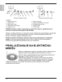
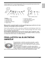
Zatvoreni (tlačni) sustav Otvoreni (protočni) sustav
POZOR! Između uređaja i sigurnosnog ventila ne smije se ugraditi zaporni
ventil jer bi se time onemogućio rad uređaja.
Grijalicu možete priključiti na vodovodnu mrežu objekta bez redukcijskoga ventila ako
je tlak u mreži niži od nazivnoga tlaka. Ako tlak u mreži premašuje nazivni tlak,
morate obvezatno ugraditi redukcijski ventil.
Grijalicu morate obvezatno napuniti vodom prije priključenja na električnu
mrežu. Prilikom prvoga punjenja otvorite ručku s toplom vodom na miješalici.
Grijalica je puna kada voda protječe kroz cijev miješalice.
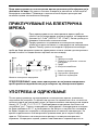
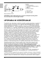
PRIKLJUČIVANJE NA ELEKTRIČNU
MREŽU
Najprije s raspakirane grijalice odvijačem skinite zaštitnu kapu s
njezina kućišta. Prije priključivanja na električnu mrežu u
grijalicu treba ugraditi priključnu vrpcu minimalna promjera od
najmanje 1,5 mm
2
(H05VV-F 3G 1,5 mm
2
).
Priključivanje grijalice na električnu mrežu mora se obaviti
sukladno standardima za postavljanje električnih instalacija.
Između grijalice vode i trajne instalacije mora biti ugrađen
uređaj za odvajanje svih polova od električne mreže sukladno nacionalnim
instalacijskim propisima.
Legenda:
1 - Sigurnosni ventil
2 - Ispitni ventil
3 - Nepovratni ventil
4 - Redukcijski ventil tlaka
5 - Zaporni ventil
6 - Ispitni nastavak
7 - Čašica s priključkom na izljev
8 - Ekspanzijska posuda
H - Hladna voda
T - Topla voda

19
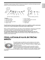
HR/BIH
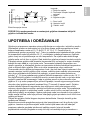
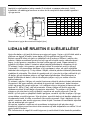
Legenda:
1 - Priključna spojka
2 - Termostat i dvopolni toplinski
osigurač
3 - Grijač
4 - Signalno svjetlo
L - Fazni vodič
N - Neutralni vodič
- Zaštitni vodič
Električna spojna shema
POZOR! Prije svakoga zahvata u unutarnjost grijalice obvezatno isključiti
grijalicu iz električne mreže.
UPOTREBA I ODRŽAVANJE
Grijalica je pripravna za uporabu nakon priključenja na vodovodnu i električnu mrežu.
Okretanjem gumba na termostatu koji je s donje strane zaštitnoga poklopca, birate
željenu temperaturu vode od 10 °C do 65 °C +5 °C/-0 °C. Preporučuje se
podešavanje gumba na položaj "eco". Takvo je podešavanje najekonomičnije; pritom
će temperatura vode biti približno 55 °C, a izdvajanje vodenoga kamenca i toplinski
gubici manji su od podešavanja na višu temperaturu. Za vrijeme rada električnoga
grijača može se čuti šum u grijalici. Rad električne grijalice prikazuje kontrolno svjetlo.
S prednje strane grijalica ima bimetalni termometar koji se naginje u smjeru kretanja
kazaljki na satu kada je u njoj topla voda. Termometar prikazuje temperaturu na
mjestu ugradnje, a okretanjem gumba na termostatu možete podešavati temperaturu
vode u donjem dijelu grijalice. Zato se te dvije temperature mogu razlikovati.
Termometar okvirno prikazuje temperaturu vode i ne služi kao mjerni instrument. Ako
nemate namjeru koristiti grijalicu dulje vrijeme, zaštitite njezin sadržaj od smrzavanja
tako da ne prekidate dovod električne energije, a gumb termostata podesite na
položaj " ". Pri tome podešavanju grijalica održava temperaturu vode na oko 10 °C.
Ako želite isključiti grijalicu iz električne mreže, morate ispustiti vodu z nje kako biste
spriječili opasnost od smrzavanja. Voda iz grijalice prazni se kroz dovodnu cijev
grijalice. U tu je svrhu preporučljivo prilikom ugradnje, između sigurnosnoga ventila i
dovodne cijevi grijalice postaviti poseban fiting (T-komad) ili ispusni ventil. Grijalicu
možete također isprazniti neposredno kroz sigurnosni ventil pomicanjem ručice,
odnosno okretne kapice ventila u položaj kao prilikom provjere rada. Prije pražnjenja
valja isključiti grijalicu iz električne mreže, a zatim otvoriti ručicu za toplu vodu na
priključenoj bateriji za miješanje. Nakon pražnjenja vode kroz dovodnu cijev grijalice
ostaje manja količina vode koja prilikom uklanjanja grijaće prirubnice iscuri kroz otvor
grijaće prirubnice.
Vanjski dio grijalice čistite blagom otopinom deterdženta. Nemojte koristiti gruba
sredstva za čišćenje.
Redovitim servisnim pregledima osigurat ćete besprijekoran rad i dug životni vijek
grijalice. Jamstvo za protukorozijsku zaštitu kotla vrijedi samo ako ste obavljali
propisane redovite preglede istrošenosti zaštitne anode. Intervali između
pojedinačnih redovitih pregleda ne smiju biti dulji od razdoblja koje je navedeno u

20
HR/BIH
jamstvenoj izjavi. Preglede mora obavljati ovlašteni serviser koji evidentira pregled na
jamstvenome listu proizvoda. Prilikom pregleda provjerava istrošenost
protukorozijske zaštitne anode i prema potrebi čisti vodeni kamenac koji se s obzirom
na kvalitetu, količinu i temperaturu potrošene vode nakuplja u unutarnjosti grijalice.
Servisna služba poslije pregleda grijalice, s obzirom na utvrđeno stanje, preporuča i
datum naredne kontrole.
POZOR! Eventualne kvarove grijalice nemojte popravljati sami već potražite
stručnu intervenciju najbliže ovlaštene servisne službe.
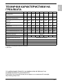
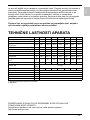
TEHNIČKA SVOJSTVA UREĐAJA
1) Uredba komisije EU 812/2013; EN 50440
2) EN 50440
PRIDRŽAVAMO PRAVO NA IZMJENE KOJE NE UTJEČU NA FUNKCIONALNOST
UREĐAJA.
Upute za uporabu dostupne su i na našoj internetskoj stranici
http://www.gorenje.com .
Tip
TGR 30 N TGR 50 N TGR 80 N TGR 100 N TGR 120 N TGR 150 N TGR 200 N
Deklarirani profil opterećenja
S M M L L XL XL
Razred energetske učinkovitosti
1)
C C C C C C D
Energetska učinkovitost pri
zagrijavanju vode (ƞwh)
1)
33,1 36,0 36,0 37,1 37,0 38,0 35,2
[%]
Godišnja potrošnja električne
energije
1)
558 1427 1428 2762 2770 4413 4756
[kWh]
Dnevna potrošnja električne
energije
2)
2,671 6,692 6,698 12,850 12,901 20,401 22,430
[kWh]
Postavka temperature na termostatu "eco" "eco" "eco" "eco" "eco" "eco" "eco"
Vrijednost oznake "smart" 0 0 0 0 0 0 0
Korisna zapremnina
30,4 48,1 73,0 93,4 110,7 139,8 195,4
[l]
Količina miješane vode pri 40 °С
V40
2)
- 67 92 131 155 212 274
[l]
Vrijeme zagrijavanja od 10 °С
do 65 °С
0:59 1:34 2:20 3:10 3:46 4:42 6:32 [h]
Nazivni tlak 0,6 (6)
[MPa
(bar)]
Masa grijalice/napunjene vodom
15,5/45,5
21/71 27/107 31/131 35/155 41/191 65/265 [kg]
Zaštita kotla od korozije Emajlirano / Mg anoda
Snaga električnoga grijača 2000 [W]
Priključni napon 230 [V~]
Klasa zaštite I
Stupanj zaštite IP23
Seite laden ...
Seite laden ...
Seite laden ...
Seite laden ...
Seite laden ...
Seite laden ...
Seite laden ...
Seite laden ...
Seite laden ...
Seite laden ...
Seite laden ...
Seite laden ...
Seite laden ...
Seite laden ...
Seite laden ...
Seite laden ...
Seite laden ...
Seite laden ...
Seite laden ...
Seite laden ...
Seite laden ...
Seite laden ...
Seite laden ...
Seite laden ...
Seite laden ...
Seite laden ...
Seite laden ...
Seite laden ...
-
 1
1
-
 2
2
-
 3
3
-
 4
4
-
 5
5
-
 6
6
-
 7
7
-
 8
8
-
 9
9
-
 10
10
-
 11
11
-
 12
12
-
 13
13
-
 14
14
-
 15
15
-
 16
16
-
 17
17
-
 18
18
-
 19
19
-
 20
20
-
 21
21
-
 22
22
-
 23
23
-
 24
24
-
 25
25
-
 26
26
-
 27
27
-
 28
28
-
 29
29
-
 30
30
-
 31
31
-
 32
32
-
 33
33
-
 34
34
-
 35
35
-
 36
36
-
 37
37
-
 38
38
-
 39
39
-
 40
40
-
 41
41
-
 42
42
-
 43
43
-
 44
44
-
 45
45
-
 46
46
-
 47
47
-
 48
48


Gorenje TGR100NG Benutzerhandbuch
- Typ
- Benutzerhandbuch
Verwandte Papiere
-
Gorenje TGR80N/D Bedienungsanleitung
-
Gorenje TGRK 120 L Benutzerhandbuch
-
-
-
-
-
-
-
Gorenje GBK150LN Benutzerhandbuch
-
Sonstige Unterlagen
-
 Eldom Invest 30-150 Household Electric Water Heaters Bedienungsanleitung
-
Eldom Invest Household Electric Water Heaters Benutzerhandbuch
-
Panasonic HR-200 Bedienungsanleitung
-
Dimplex DHWE 50 S Benutzerhandbuch
-
AE EHT 80I Operating And Mounting Instructions Manual
-
 Wilhelm Schildmeyer 753365 Assembly Instructions Manual
-
-
-
Marley 10723440 Benutzerhandbuch

