
SELF-PRIMMING PUMPS FOR SWIMMING-POOLS
SELBSTANSAUGENDE PUMPEN FÜR SCHWIMMBECKEN
INSTALLATION AND MAINTENANCE MANUAL. TECHNICAL DATA.
HINWEISE FÜR EINBAU UND WARTUNG. TECHNISCHE DATEN.
(SA – ENG-GER)

ENGLISH
IMPORTANT: The manual you are reading contains fundamental information regarding the
safety measures to be adopted when installing and starting up. It is therefore of utmost
importance that both the installer and the user read the instructions before assembling and
starting up.
1. GENERAL SAFETY INSTRUCTIONS
These symbols ( ) represent the possibility of danger as a result
of not following the corresponding instructions.
DANGER. Electrocution risk.
Non-compliance with this instruction involves a risk of electrocution.
DANGER. Non-compliance with this instruction involves a risk of danger to people or
things.
ATTENTION. Non-compliance with this instruction involves a risk of damaging the
pump or the unit.
2. GENERAL SAFETY RULES
GENERAL OBSERVATIONS
The machines mentioned in this manual are especially designed to carry out the pre-
filtration and the circulation of water in swimming pools.
They are designed to work with clean water at a temperature that does not exceed 45ºC.
Installation should be carried out in accordance with the specific indications for each
step.
The regulations in force for the prevention of accidents should be heeded.
Any modification that may be made to the pump requires the previous authorisation of
the manufacturer. The original manufacturer-authorised spares and accessories
guarantee greater safety. The pump manufacturer is exempt from all responsibility for
damage caused by the use of unauthorised spares or accessories.
During operation the electrical parts of the pump are live. Work can only be carried out
on each machine or on connected-equipment after having disconnected them from the
electrical supply network and having disconnected the starting mechanisms.
The user must make sure that assembly and maintenance work is carried out by
qualified and authorised people who have previously carefully read the installation and
service instructions.
The operating safety of the machine is only guaranteed with the compliance and respect
for that mentioned in the installation and service instructions.
In the case of defective operation or breakdown, contact the nearest manufacturer’s
agent or the manufacturer’s Technical Customer Service.
DEUTSCH
Bitte beachten Sie: Diese Anleitung enthält wichtige Sicherheitsbestimmungen, deren
Einhaltung bei der Installation und der Inbetriebnahme unbedingt erforderlich ist. Lesen Sie bitte
vor der Montage und der Nutzung alle Anweisungen.
1. ALLGEMEINE SICHERHEITSHINWEISE
Die folgenden Symbole ( ) weisen auf mögliche Gefahren bei
Nichtbeachtung der entsprechenden Sicherheitsvorschriften hin.
LEBENSGEFAHR.
Die Nichtbeachtung dieser Vorschrift kann zu tödlichen Stromschlägen führen.
GEFAHR. Die Nichtbeachtung dieser Vorschrift kann zu Personen- oder Sachschäden
führen.
VORSICHT. Die Nichtbeachtung dieser Vorschrift kann zu Schäden an der Pumpe
oder der Anlage führen.
2. ALLGEMEINE SICHERHEITSBESTIMMUNGEN
ALLGEMEINES
Die in dieser Anleitung genannten Geräte werden für die Vorfiltrierung und
Wasserumwälzung in Schwimmbecken hergestellt.
Sie sind für den Einsatz mit sauberem Wasser mit einer Temperatur nicht über 45°C
vorgesehen.
Die Installation muss unter genauer Beachtung der jeweiligen Einbauanleitung erfolgen.
Beachten Sie die allgemeinen Unfallverhütungsvorschriften!
Jede beabsichtigte Veränderung an der Pumpe bedarf der vorherigen Genehmigung
durch den Hersteller. Originalersatzteile und vom Hersteller zugelassenes Zubehör
garantieren für erhöhte Sicherheit. Der Hersteller übernimmt keine Verantwortung für
Schäden, die durch die Verwendung von nicht zugelassenem Zubehör oder nicht
zugelassenen Ersatzteilen entstehen.
Während des Betriebes stehen die elektrischen Teile der Pumpen unter Spannung. Vor
Wartungsarbeiten am Gerät oder an angeschlossenen Anlagen müssen die Stromzufuhr
unterbrochen und die Anlaufeinrichtugen abgeschaltet werden.
Der Benutzer muss sich vergewissern, dass Montage- und Wartungsarbeiten nur durch
qualifizierte und autorisierte Fachleute ausgeführt werden, die mit der Installations- und
Bedienungsanleitung vertraut sind.
Ein zuverlässiger Betriebsablauf kann nur bei genauer Einhaltung der Anleitungen
garantiert werden.
Im Falle einer Störung oder eines fehlerhaften Betriebsablaufs wenden Sie sich bitte an
den nächsten Vertragshändler oder an den offiziellen Kundendienst.

INSTALLATION AND ASSEMBLY WORK WARNINGS
While connecting electrical cables to the machine’s motor, take care of the mechanism
inside the connection box, check that no pieces of cable remain inside after closure and
that the earth contact is correctly connected. Connect the motor using the electrical
diagram attached to the machine.
Check that the electrical cable connections to the machine’s terminal box are well set
and firmly attached to the connection terminals.
The pump electrical installation should have a differential the value of which is not
greater than 30mA.
Check that the terminal box joint is used correctly, thus preventing water from entering
the terminal box of the electric motor. Likewise, check that the packing gland has been
placed and pressed correctly inside the joint.
The pumps must always be fixed horizontally, especially models with pre-filter.
It is always advised to install them below water level, especially those that are not "self
priming" (centrifugal pumps). Models type "self-priming" can be installed above water
level, but the geometric height should not exceed 2 meters. Moreover, the suction pipe
should be as short as possible to reduce suction time. Also, make sure that the place
where the pump will be installed is always dry and airy.
Special attention should be paid to ensure that under no circumstances water gets into
the motor and the electric voltage parts.
Should the envisaged use not be different from that mentioned, adaptations and
supplementary technical regulations might be necessary.
STARTING-UP WARNINGS
Before starting the pump for the first time, verify the calibration of the motor electric
protection mechanisms and check that the protectors against electrical and mechanical
contacts are correctly positioned and well fixed.
It is recommended not to use the pool during that first check of the pumping equipment
installation.
ASSEMBLY AND MAINTENANCE WORK WARNINGS
National installation regulations should be taken into account when assembling and
installing the pumps.
Special attention should be paid to ensure that under no circumstances water gets into
the motor and the electric voltage parts.
Any contact, even accidental, with the machine’s moving parts should be avoided while
the machine is operating and/or before it completely stops.
Wait until the machine has completely stopped in order to carry out any work on it.
Before undertaking any electrical or mechanical maintenance make sure that the
machine has been disconnected from the supply network and starting-up mechanisms
are blocked.
Before working on the machine it is advisable to follow the steps below:
1. Cut the machine voltage.
2. Block the starting-up mechanisms.
3. Check that there is no voltage in the circuits, including the auxiliaries and
supplementary services.
4. Wait until the wheel has stopped completely.
HINWEISE ZU INSTALLATIONS- UND MONTAGEARBEITEN
Beachten Sie beim Anschluss der Elektrokabel an den Motor die richtige Anordnung im
Inneren des Anschlusskastens. Lassen Sie keine Kabelreste im Inneren zurück und
vergewissern Sie sich, dass die Erdleitung korrekt angeschlossen ist. Schliessen Sie
den Motor entsprechend dem der Pumpe beiliegenden Schaltplan an.
Kontrollieren Sie, dass die Elektrokabel richtig an den Anschlussklemmen des
Verbindungskastens der Maschine eingepasst und befestigt sind.
Die Pumpen müssen über eine Fehlerstrom-Schutzeinrichtung (RCD) mit einem
Bemessungsstrom von nicht mehr als 30mA versorgt werden.
Vergewissern Sie sich, dass die Dichtung des Anschlusskastens korrekt schließt und
kein Wasser in den Anschlusskasten des Elektromotors eindringen kann. Vergewissern
Sie sich auch, dass die Stopfbüchse im Inneren der Kabelführung des Anschlusskastens
angebracht und gut befestigt ist.
Die Pumpen müssen in horizontaler Lage befestigt werden, das gilt insbesondere für die
Modelle mit Vorfilter.
Es wird generell ein Einbau unterhalb des Wasserspiegels empfohlen, besonders bei
den „nicht selbstansaugenden“ Modellen (Kreiselpumpe). Selbstansaugende Modelle
können oberhalb des Wasserspiegels eingebaut werden, wobei aber die geometrische
Höhe nicht mehr als zwei Meter betragen darf. Andererseits muss die Saugleitung so
kurz wie möglich sein, um die Ansaugzeit zu verringern. Vergewissern Sie sich auch,
dass der Raum, in dem sich die Pumpe befindet, stets trocken und belüftet ist.
Der Motor und die stromführenden Geräteteile dürfen auf keinen Fall mit Wasser in
Berührung kommen.
Wenn das Gerät für einen anderen als den hier genannten Zweck verwendet werden
soll, können Anpassungen und zusätzliche technische Normen nötig werden.
HINWEISE ZUR INBETRIEBNAHME
Vor der ersten Inbetriebnahme des Geräts muss die Eichung der elektrischen
Schutzvorrichtungen des Motors geprüft werden und es muss sichergestellt sein, dass die
Abdeckungen zum Schutz vor mechanischem und elektrischem Kontakt richtig angebracht
und befestigt sind.
Es wird empfohlen, bei der ersten Betriebsprüfung der Pumpanlage das Bad nicht zu
benutzen.
HINWEISE ZU MONTAGE UND WARTUNG
Bei der Montage und Installation der Pumpen sind die nationalen
Installationsvorschriften zu beachten.
Achten Sie strikt darauf, dass kein Wasser in den Motor und in stromführende
Geräteteile eindringen kann.
Vermeiden Sie während des Betriebsablaufs und solange die Maschine nicht völlig zum
Stillstand gekommen ist, jede, auch versehentliche, Berührung mit den beweglichen
Teilen der Maschine.
Warten Sie, bis die Maschine zum Stillstand gekommen ist, bevor Sie Arbeiten daran
ausführen.
Stellen Sie sicher, dass die Maschine vom Stromnetz getrennt ist und die
Anlaufvorrichtungen gesperrt sind, bevor Sie elektrische oder mechanische
Wartungsarbeiten durchführen.
Vor allen Arbeiten am Gerät beachten Sie bitte die folgenden Schritte:
1. Ziehen Sie den Netzstecker.
2. Sperren Sie die Anlaufvorrichtung.
3. Vergewissern Sie sich, dass weder im Stromkreis noch im Hilfsstromkreis oder

The mentioned list should be considered indicative and not binding, since there may be
specific safety rules within specific safety procedures.
Periodically control:
- The mechanical parts are firmly secured and the machine support screws are in
good condition.
- Correct positioning and fixing and the condition of the leading-in wires and
isolation components.
- Machine and electric motor temperature. In case of irregularity, stop the machine
immediately and proceed with its repair.
- Machine vibrations. In case of irregularity, stop the machine immediately and
proceed with its repair.
Because of the complexity of cases dealt with, the installation, use and maintenance
instructions in this manual do not intend to examine and deal with all possible service and
maintenance situations. If supplementary instructions are necessary or if specific problems
arise, do not hesitate to contact the machine distributor or the manufacturer.
The electrical installation must be performed by qualified personnel in electrical
installations. This equipment is intended for people with reduced physical, sensory or
mental capacities or with no experience, unless they have had supervision or instructions
on its use by a security officer.
Do not allow children or adults to lean or sit on the device. Children should be supervised
to ensure they do not play with the equipment.
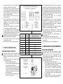
3. INSTALLATION AND ASSEMBLY
GENERAL
Assembly and installation of our pumps is only
permitted in swimming pools or tanks complying with
regulation HD 384.7.702. In case of doubt please
consult a specialist.
Some pumps come with a pre-filter with an interior
basket to collect large particles since these may
damage the interior hydraulic part of the pump. This
pre-filter means that the pump assembly must be
done in a horizontal position.
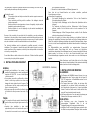
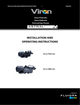
All pumps come with a two-drill foot to allow for them
to be fixed in the floor by means of an anchor. (Fig.
1).
TUBING
The connection of the pipe must be threaded into the
mouths of the pump using the right accessories (Fig.
2).
Impulsion tube installation is done totally
perpendicularly and is well centred with respect to
the nozzle to be connected so as to avoid external
den Zusatzteilen Strom fliesst.
4. Warten Sie, bis das Kreiselrad zum Stillstand gekommen ist.
Diese Liste hat nur Hinweis-Charakter und schliesst zusätzliche, spezifische
Sicherheitsnormen nicht aus.
Kontrollieren Sie regelmässig:
- Die korrekte Befestigung der mechanischen Teile und den Zustand der
Schraubenhalterung des Gerätes.
- Die richtige Position, Befestigung und den Zustand der Speiseleiter und der
Isolierung.
- Die Temperatur der Maschine und des Elektromotors. Sollten Störungen
auftreten, schalten Sie die Maschine sofort ab und veranlassen Sie die
Reparatur.
- Geräteschwingungen. Sollten Störungen auftreten, schalten Sie die Maschine
sofort ab und veranlassen Sie die Reparatur.
Es ist leider nicht möglich, im Rahmen dieser Anleitung zu Installation, Betrieb und
Wartung alle vorstellbaren Situationen beim Betrieb und bei der Wartung abzudecken.
Sollten Sie zusätzliche Anleitungen benötigen oder spezielle Probleme auftreten, zögern
Sie nicht, sich mit Ihrem Vertragshändler oder direkt mit dem Hersteller in Verbindung zu
setzen.
Die Elektroinstallation muss ausschließlich von entsprechendem Fachpersonal
durchgeführt werden. Diese Anlage darf nicht von Personen mit körperlichen,
sensorischen oder geistigen Einschränkungen bzw. von Personen ohne jegliche Erfahrung
bedient werden, es sei denn, sie sind in den Betrieb derselben durch einen
Sicherheitsbeauftragten eingewiesen worden oder werden von einer Aufsichtsperson
begleitet.
Weder Erwachsene noch Kinder dürfen sich auf die Anlage
setzen oder sich darauf abstützen. Kinder müssen beaufsichtigt
werden, damit sie nicht mit der Anlage spielen.
3. INSTALLATION UND MONTAGE
ALLGEMEINES
Die Montage und Installation unserer Pumpen ist nur an
Schwimmbecken oder Teichen erlaubt, die der Norm HD
384.7.702 entsprechen. In Zweifelsfällen wenden Sie sich
bitte an einen Fachmann.
Die Pumpen haben einen Vorfilter, der mit einem Korb
ausgestattet ist, um gröbere Partikel zurückzuhalten, die
den hydraulischen Innenraum der Pumpe beschädigen
könnten. Damit der Vorfilter seine Funktion erfüllen kann,
muss die Pumpe horizontal montiert werden.
Alle Pumpen habe einen Fuss, der zwecks Verankerung am
Boden mit vier Bohrungen versehen ist. (Abb.1)
ROHRLEITUNG
Die Rohrleitung muss unter Verwendung der
entsprechenden Zubehörteile (Abb. 2) an die
Eingangsöffnungen der Pumpe angeschraubt werden.
Installieren Sie die Druckanschlüsse genau senkrecht und in
der Mitte der entsprechenden Öffnungen. Damit vermeiden

pressure being exerted on the pump and the tube.
Apart from making assembly more difficult, this
pressure could even break them. (Fig. 2)
Suction tube installation is done at a slight angle of 2
% towards the pump, thus avoided siphon formation.
(Fig.2).
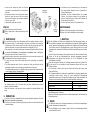
For the correct operation of the pump, it must be
primed until water reaches the surface of the suction
pipe. In models with built-in pre-filter, the pump can
be filled with water by opening the lid of the pre-filter
(Fig. 3).
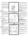
POSITIONING
It is always advised mounting the pump below the
water level in the pool or pond.
If you have to install a pump model "self-priming"
above water level, the difference in height should not
exceed 2 meters (Fig. 4), ensuring that the suction
pipe is as short as possible as, a longer pipeline
increases the suction time and the loss of head of
the installation.
It should be ensured that the pump is free from
possible flooding and it is given dry ventilation.
SAFETY INSTRUCTIONS
ALL ELECTRICAL INSTALLATIONS MUST
CORRESPOND TO THE STANDARD:
EN 60335-2-41.
"All electrical devices at 230v single phase or 400v
three-phase must be installed with a minimum distance
of 3.5 meters from the edge of the pool. For any
modification of the filtration system, the manufacturer
must be informed without fail. "
ELECTRICAL UNIT
The electrical unit should have a multiple separation
system with contact opening of at least 3 mm.
The cables used for the electrical connection must
ensure the correct fixation to the motor terminals.
A heat protector is incorporated into single-phase
pumps. In these, switch installation is sufficient as in
the “Network connection” diagram
In the three-phase motor a motor guard with heat-
magnetic protection needs to be used.
A protection differential of 30mA is needed for any
pump in order to protect from electrical escapes
(shown in diagrams).
Sie unnötige äussere Krafteinwirkungen auf Pumpe und
Rohrleitung, die nicht nur die Montage erschweren würden,
sondern auch zu einem Bruch der Teile führen könnten
(Abb. 2).
Installieren Sie die Saugleitung mit einer Neigung von 2%
zur Pumpe. Damit wird die Entstehung von Lufttaschen
verhindert (Abb. 2).
Für einen einwandfreien Betrieb der Pumpe muss diese
zum Ansaugen gebracht werden, bis das Wasser in der
Saugleitung zu sehen ist. Bei den Modellen mit
eingebautem Vorfilter kann die Pumpe durch Öffnen des
Vorfilterdeckels mit Wasser gefüllt werden (Abb.3).
AUFSTELLUNGSORT
Die Pumpe sollte immer unterhalb des Wasserspiegels des
Schwimmbads oder Teichs eingebaut werden.
Falls ein „selbstansaugendes“ Modell oberhalb des
Wasserspiegels eingebaut werden muss, darf der
Höhenunterschied nicht mehr als zwei Meter betragen (Abb.
4). Es ist auch wichtig, darauf zu achten, dass die
Ansaugleitung so kurz wie möglich ist, da sich im
gegenteiligen Fall die Ansaugzeit verlängert und der
Druckverlust erhöht.
Schützen Sie die Pumpe vor Überschwemmungen und
sorgen Sie für eine trockene Belüftung.
SICHERHEITSHINWEISE
SÄMTLICHE ELEKTROINSTALLATIONEN MÜSSEN DER
VORSCHRIFT EN 60335-2-41 ENTSPRECHEN.
„Jedes elektrische Gerät mit einphasiger 230 V- oder
dreiphasiger 400 V-Versorgung muss in einer
Mindestentfernung von 3,5 Meter vom Schwimmbeckenrand
installiert werden. Bei jeglicher Änderung des Filtersystems
muss umgehend der Hersteller informiert werden“.
ELEKTRISCHE INSTALLATION
Die elektrische Installation muss über eine mehrstufige
Trennung mit einer Kontaktöffnung von mindestens 3mm
verfügen.
Die für die Elektroinstallation verwendeten Kabel müssen
eine vorschriftsmäßige Befestigung an den Motorklemmen
sicherstellen.
In die Einphasenpumpen ist ein Thermo-Schutzschalter
eingebaut. Es genügt also die Installation mit Schalter wie
im Schema “Netzanschluss” vorgesehen.
Für den Dreiphasen-Motor muss unbedingt ein
magnetothermischer Motorschutzschalter verwendet
werden.
Bei allen Pumpenmodellen muss ein
Differentialschutzschalter von 30mA als Schutz vor
Stromschlägen eingesetzt werden.

Three-phase motors should be protected from
overload by a safety switch for the motor.
We recommend using a connection cable type H07
RN-F type of an appropriate section according to the
power consumption of the pump motor and the
number of drivers required for the number of motor
phases plus the ground cable.
Before connecting the motor, check the type of
protection required.
For three-phase motors, adjust suitably the heat
value according to the heat protector table. For
connection “” set the protector at the highest
indicated value. For connection “” set the protector
at the lowest value.
Check the correct arrangement and connection of
the earth wire in the equipment installation.
It is very important to keep to the installation and
electrical connection conditions. Should they not be
heeded, the pump manufacturer does not accept any
responsibility and considers the guarantee void.
The motors are subject to EEC standards with IP-55.
Special installation regulations may exist.
The main cable can only be connected by qualified
and authorised personnel.
Incorrect mains connection could result in death.
4. START-UP INSTRUCTIONS
QUESTIONS PRIOR TO START-UP
The pumps can never work without having been
previously filled with water, as otherwise it may
damage the mechanical seal causing loss of water
through it.
For models with pre-filter the following operations
can be performed (Fig. 3):
1. Open the lid of the pre-filter (Fig. 5).
2. Fill the pump with water through the pre-filter
until it dips into the suction tube.
3. If, during these operations the basket should
have been taken out, do not forget to replace
it inside the pre-filter so as to prevent large
particles from entering the inside of the pump
and thus blocking it
4. Close the pre-filter without forgetting to place
the joint in their seat. (Fig. 5)
Die Dreiphasenpumpen müssen mit einem Schutzschalter
verschen sein um die überhitzung des Motors zu vermeiden.
Es wird empfohlen, ein Anschlusskabel des Modells H07
RN-F mit geeignetem Durchmesser für den Stromverbrauch
des Pumpenmotors zu verwenden, das darüber hinaus eine
angemessene Anzahl Adern für die Phasenzahl des Motors
zuzüglich des Erdungskabels hat.
Vor Anschluss des Motors muss die benötigte
Schutzvorrichtung geprüft werden.
Beim Dreiphasen-Motor stellen Sie das Thermorelais
entsprechend den Angaben der Wärmeschutzschalter-
Tabelle ein. Für die Verbindung im Dreieck () gilt der
höhere der genannten Werte. Für ein eine „Y“ Verbindung
gilt entsprechend der niedrigere Wert.
Beachten Sie beim Einbau der Anlage die korrekte
Verlegung und Verbindung der Erdungsleitung.
Bei Missachtung der Anleitungen zu Einbau und
Elektoranschluss lehnt der Hersteller jede Verantwortung ab
und die Garantie geht verloren.
Die Motoren unterliegen den EWG-Vorschriften mit
Schutzklasse IP-55.
Es können besondere Einbau-Richtlinien bestehen.
Das Netzkabel ist nur von autorisiertem Fachpersonal
anzuschlieen.
Falscher Netzanschluss kann lebensgefährlich sein!
4. ANWEISUNGEN ZUR INBETRIEBNAHME
VOR DER INBETRIEBNAHME
Die Pumpen dürfen unter keinen Umständen in Betrieb
genommen werden, wenn sie nicht vorher mit Wasser
gefüllt worden sind, da im gegenteiligen Fall die
Verschlussdichtung beschädigt werden könnte, was zum
entsprechenden Wasserleck führt.
Bei den Modellen mit Vorfilter können folgende Schritte
durchgeführt werden (Abb.3):
1. Abdeckung des Vorfilters öffnen (Abb.5).
2. Füllen Sie Wasser durch den Vorfilter in die Pumpe
bis das Wasser in der Saugleitung erscheint.
3. Falls Sie während dieser Handgriffe den Korb aus
dem Inneren des Vorfilters entfernt haben,
vergessen Sie nicht, ihn wieder einzusetzen, denn
nur so können Sie vermeiden, dass gröbere Partikel
ins Pumpeninnere dringen und möglicherweise die
Pumpe verstopfen.
4. Vorfilter schließen, ohne dabei zu vergessen, die
Dichtung in ihrer Aufnahme zu platzieren. (Abb.5)
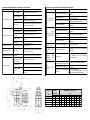
CODE VOLTAGE INTENSITY RELAY REGULATION
Code Voltzahl Intensitätsrelais-Verordnung
SA033M 230 V 2,9 A
SA050M 230 V 3,8 A
SA075M 230 V 4,0 A
SA075T 230/400 V 2,4 / 1,6 A
SA100M 230 V 6,2 A
SA100T 230/400 V 4,7 / 2,7 A
SA125M 230 V 7,6 A
SA125T 230/400 V 6,1 / 3,5 A

Check that the voltage and power of the mains
correspond to those determined in the nameplate of
the pump.
In three-phase motors check that the motor rotation
direction is correct, by means of the fan located in
the rear part of the motor, seen through the peephole
in the fan cover. (Fig.6)
Check that the pump axle turns freely.
START-UP
Open all valves and connect the motor.
Wait a suitable time for tubing auto-priming to take
place.
5. MAINTENANCE
In models with pre-filter, the pre-filter basket should be regularly cleaned in order to
avoid pressure drops. To avoid breakage of the basket, you should not hit during the
cleaning process. Every time you open the pre-filter, clean the joint and the seat of the
joint of any impurities, to ensure a good sealing when shutting the lid. (Fig.5).
If the pump stops, check that the motor amp consumption during his working is the same
or less than that indicated on the manufacturer’s specification board, or failing him,
contact the nearest Customer Technical Service..
Empty the pump in cases where it must remain without use for some time, mainly in cold
countries where there may be danger of freezing.
To empty the pump, remove the draining plug from the pump body (see explosion
drawing).
The pump components which, due to its regular use, suffer wear and tear must be
periodically replaced in order to maintain a good performance of the pump.
The following table provides a list of fungible pump components and/or components that
can be damaged and their estimated lifetime.
COMPONENT DESCRIPTION
LIFETIME ESTIMATE
O-rings and sealing elements in general
1 year
mechanical seal
1 year
Ball bearings
1 year
The estimated period of life of the parts above has been established under normal
conditions of product installation.
Follow the instructions in the manual in order to maintain the estimated lifetime of the
pump.
6. DISMANTLING
The motor unit may be dismantled from the pump body without needing to disconnect
the pump’s suction and impulsion tubing.
To disconnect the motor unit from the pump body, remove the screws that join them (see
explosion drawing).
Sicherstellen, dass die Netzspannung und -kapazität mit
den entsprechenden Angaben auf dem Typenschild der
Pumpe übereinstimmen.
Überprüfen Sie beim Dreiphasen-Motor den richtigen
Drehsinn. Den Drehsinn erkennen Sie am Ventilator im
hinteren Teil des Motors, den Sie durch das Sichtfenster im
Deckel sehen können (Abb. 6).
Die Achse der Pumpe muss sich frei drehen können.
INBETRIEBNAHME
Öffnen Sie alle Ventile und lassen Sie den Motor an.
Warten Sie, bis die Selbstfüllung der Leitung erfolgt.
5. WARTUNG
Bei den Modellen mit Vorfilter muss regelmäßig der Filterkorb gereinigt werden, um
Druckverluste zu vermeiden. Bei der Reinigung darf nicht gegen den Filterkorb gestoßen
werden, da dieser beschädigt oder sogar zerbrochen werden könnte. Bei jeder Öffnung
des Vorfilters müssen die Dichtungsaufnahme und die Dichtung selbst von Schmutz
gereinigt werden, um damit die Dichtheit beim Schließen der Abdeckung sicherzustellen
(Abb.5).
Falls die Pumpe stehen bleiben sollte, vergewissern sie sich, dass die Amper-Zahl des
Motors mit der auf der Geräteplakette vom Hersteller angegebenen Amperzahl
übereinstimmt, oder darunter liegt. Wenden Sie sich im Zweifelsfall an einen
Kundendienst in Ihrer Nähe.
Wenn die Pumpe eine Zeit lang nicht in Betrieb genommen werden soll, entleeren Sie
sie bitte vorher. Dies ist besonders in kalten Gegenden wichtig, wo die Rohre sonst
einfrieren könnten.
Um die Pumpe zu leeren, ziehen Sie den Stöpsel vom Gehäuse der Pumpe (siehe
Ersatzteil Zeichnen).
Die Pumpenbestandteile, die aufgrund der regelmäßigen Verwendung abgenutzt bzw.
verschlissen werden können, müssen für einen problemlosen Pumpenbetrieb
regelmäßig ersetzt werden. Die folgende Aufstellung zeigt die Pumpenbestandteile, die
Verbrauch und Verschleiß ausgesetzt sind, sowie die geschätzte Lebensdauer.
BESCHREIBUNG
GESCHÁTZTE LEBENSDAUER
O-Ring-Dichtung und allgemeine Dichtungselemente
1 Jahr
Formverschluss
1 Jahr
Wälzlager
1 Jahr
Die geschätzte Lebensdauer der aufgeführten Teile beruht auf üblichen
Einbaubedingungen des Produktes.
Befolgen Sie die Anweisungen der Betriebs- und Einbauanweisung für die Ausnutzung der
Pumpenlebensdauer.
6. ABBAU
Der Motorblock kann von der Pumpe getrennt werden, ohne vorher die Ansaugleitungen
und den Pumpenantrieb abzumontieren.
Um den Motorblock von der Pumpe zu trennen, lösen Sie die Verbindungsschrauben
(siehe Ersatzteil Zeichnen).

POSSIBLE BREAKDOWNS, CAUSES AND SOLUTIONS
PROBLEMS CAUSES SOLUTIONS
Air entry in suction tube Check pipe fittings and suction tube joints
Bad filter cover sealing
Clean the pre-filter cover and check the condition of
the joint
Motor turning direction
incorrect.(III)
Invert two phases of the feeding line
Wrong voltage
Check that the network voltage corresponds to that on
the motor specification board
Blocked pre-filter Clean the pre-filter
Air entry in suction tube Check pipe fittings and suction tube joints
Motor turning direction
incorrect.(III)
Invert two phases of the feeding line
Load loss in suction
Prevent as much as possible, elements that produce
load loss
Wrong voltage
Check that the network voltage corresponds to that on
the motor specification board
PUMP MAKES A NOISE
Incorrect fixation of the pump Fix pump correctly
PUMP WILL NOT START
Wrong voltage
Check that the network voltage corresponds to that on
the motor specification board
THE MOTOR MAKES A
NOISE BUT DOESN’T START
Blocked motor Dismantle the motor and contact the technical service.
Increase in terminal box
temperature because of
voltage arch effect
Check terminal box connections
Heat protector blows Correctly connect cables with terminal box terminals
Fasten the cable to the terminal correctly
Modify size of connection cable to terminal box
terminals
THE MOTOR STOPS
Terminal boxes badly
connected
THE PUMP DOES NOT PRIME
THE PUMP GIVES LOW FLOW
MÖGLICHE STÖRUNGEN, URSACHEN UND BESEITIGUNG
PROBLEM
URSACHE
LÖSUNG
DIE PUMPE FÜLLT
SICH NICHT AUF
Lufteintritt durch die Saugleitung
Gewinde und Dichtungen der Saugleitung
überprüfen
Filterdeckel undicht
Deckel des Vorfilters reinigen, Zustand der
Dichtungen überprüfen
Drehsinn des Motors nicht korrekt
(III)
Zwei Versorgungsphasen umkehren
Falsche Stromspannung
Netzspannung muss dem Typenschild
entsprechen
DIE PUMPE
LIEFERT WENIG
FÖRDERLEISTUN
G
Vorfilter verstopft
Vorfilter reinigen
Lufteintritt durch die Saugleitung
Gewinde und Dichtungen der Saugleitung
überprüfen
Drehsinn des Motors ist nicht
korrekt (III)
Zwei Versorgungsphasen umkehren
Druckverlust beim Ansaugen
Teile, die zu Druckverlust führen, vermeiden
Falsche Stromspannung
Netzspannung muss dem Typenschild
entsprechen
DIE PUMPE
MACHT LÄRM
Pumpe ist nicht richtig befestigt
Pumpe richtig befestigen
DIE PUMPE
SPRINGT NICHT
AN
Falsche Stromspannung
Netzspannung muss dem Typenschild
entsprechen
DER MOTOR
MACHT LÄRM,
SPRINGT ABER
NICHT AN
Motor blockiert
Motor ausbauen und zum technischen
Kundendienst bringen.
MOTOR LÄUFT
NICHT
Temperaturerhöhung im
Klemmenkasten durch Lichtbogen
Anschlüsse im Klemmenkasten überprüfen
Wärmeschutzschalter springt raus
Kabel korrekt an den Klemmenkasten
anschliessen
Anschlüsse im Klemmenkasten
fehlerhaft
Kabel richtig befestigen.
Grösse der Kabelverbindung an den
Anschluss im Klemmenkasten anpassen
kW CV/HP A B C D E F G H I
SA033
0,25 1/3 475 296 280 Ø50 225 200 285 199 168
SA050
0,37 1/2 475 296 280 Ø50 225 200 285 199 168
SA075
0,55 3/4 490 311 280 Ø50 225 200 285 199 168
SA100
0,75 1 490 311 280 Ø50 225 200 285 199 168
SA125
1,10 1,5 490 311 280 Ø50 225 200 285 199 168
mm
DIMENSIONS _ Abmessugen
CODE
POWER
Code
Leistung

We reserve the right to change all or part of the articles or contents of this document, without prior notice.
Wir behalten uns das recht vor, die merkmale unserer produkte und den inhalt dieser beschreibung ohne vorherige
ankündigung ganz oder teilweise zu ändern.
EVIDENCE OF CONFORMITY / KONFORMITÄTSERKLÄRUNG
Manufactured by: / Hergestellt von:
A-17/453.267
Pol. Ind. La Rasa
C/ Muntanya s/n
17481 Sant Julià de Ramis
(Girona) Spain
- Declares under their own responsibility that all the pumps: TORPEDO
Manufactured since 20/04/2016, independent of the serial number, are in compliance with:
o 2006/42/CE Machine directive safety prescriptions.
o 2014/30/CE Electromagnetic compatibility directive.
o 2014/35/CE Low voltage Directive.
o EN 60335-1 EN60335-2-41
- Bescheinigt in alleiniger verantwortung, dass alle Pumpen des typs: TORPEDO
Ab 20/04/2016, produziert wurden, unabhängig von der seriennummer, konform sind mit:
o Richtlinie 2006/42/CE über die sicherheit von maschinen.
o Richtlinie 2014/30/CE über elektromagnetische verträglichkeit.
o Richtlinie 2014/35/CE über die sicherheit von electrischen betriebsmitteln
(Niederspannungsrichtlinie).
o EN 60335-1 EN60335-2-41
Signed the present conformity evidence / Unterzeichnet diese erklärung
Sant Julià de Ramis, 20/04/2016
Unterschrift /Signature
Carme Fusté Caixàs, Managing Director of A-17/453.267
67 dBA 73 dBA
SA033M SA050M SA075M SA100M SA125M
SA075T SA100T SA125T
78 dBA
INDICATIONS ON THE MAXIMUM AIR NOISE EMITTED
Angaben zur maximal zulässigen luftschallemission
CODE CODE CODE
Code Code Code
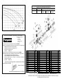
1
HD006000
16 0,33 / 0,50 CV
HD061000
32 0,33 / 0,50 CV (4 Unit)
MT101015
2
HD018000
16 0,75 / 1 / 1,5 CV
HD061005
32 0,75 / 1 / 1,5 CV ( 4 Unit)
MT101040
3
HD021000
17
HD066000
33
0,33 / 0,50 CV
MT086040
4 ( 4 Unit)
HD026055
18 0,33 / 0.50 CV
HD071005
33 0,75 / 1 / 1,5 CV
MT086045
5 ( 4 Unit)
HD031010
18 0,75 / 1 / 1,5 CV
HD071000
34 0,33 / 0,50 CV
MT086050
6 ( 4 Unit)
HD031055
19 ( 2 Unit)
MT001000
34 0,75 / 1 / 1,5 CV
MT086051
7
HD036000
20 0,33 / 0,50 CV
MT006025
35 0,33 / 0,50 CV
MT086055
8
HD021100
20 0,75 / 1 / 1,5 CV
MT006050
35 0,75 / 1 / 1,5 CV
MT086060
9
HD041000
21 ( 2 Unit)
MT026000
36 ( 2 Unit)
HD076010
10
HD021035
24
MT081030
37 ( 2 Unit)
HD021115
11
HD046005
26 1-PH
MT081035
38 ( 2 Unit)
HD076005
12
HD031075
26 3-PH
MT081045
39
HD076000
13 0,33 CV
HD051005
27
MT076050
40 0.33 CV 1-PH
MT999000
13 0,50 CV
HD051010
28 1-PH
MT088000
40 0.50 CV 1-PH
MT999005
13 0,75 CV
HD051015
28 3-PH
MT088005
40 0.75 CV 1-PH
MT999010
13 1 CV
HD051025
29 0,33 / 0,50 CV 1-PH
MT091000
40 0.75 CV 3-PH
MT999015
13 1.5 CV
HD051035
29 0,75 / 1 / 1,5 CV 1-PH
MT091010
40 1 CV 1-PH
MT999020
14
HD021060
30
MT096000
40 1 CV 3-PH
MT999025
15
HD056005
31 0,33 / 0,50 CV
MT016025
40 1.5 CV 1-PH
MT999030
31 0,75 / 1 / 1,5 CV
MT016040
40 1.5 CV 3-PH
MT999035
Nº
Nº
Nº
-
 1
1
-
 2
2
-
 3
3
-
 4
4
-
 5
5
-
 6
6
-
 7
7
-
 8
8
-
 9
9


Torpedo SA100T Installation and Maintenance Manual
- Typ
- Installation and Maintenance Manual
in anderen Sprachen
- English: Torpedo SA100T
Sonstige Unterlagen
-
Astralpool Pool Pumps Bedienungsanleitung
-
 Vogel Aspri Series Benutzerhandbuch
-
 Guinard Xenajet 4000 K 850w Benutzerhandbuch
-
 Guinard Dorinox 4500 K 790w Benutzerhandbuch
-
 Viron P600 eVo Bedienungsanleitung
-
Kärcher BP 4 Spezifikation
-
EINHELL GP 2800 Bedienungsanleitung
-
-
Kärcher BPP 3000 42 Bedienungsanleitung
-
Agora-Tec AT 001 008 003 Bedienungsanleitung


