
B000856
VMH SERIES
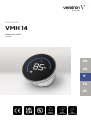
VMH 14
USER MANUAL
rev. AA
EN
DE
IT
FR
ES

B000856
LANGUAGE PAGE
ENGLISH 3
DEUTSCH 21
ITALIANO 40

VMH SERIES
VMH 14
USER MANUAL
rev. AA
EN
DE
IT
FR
ES

CONTENT
B001225
CONTENT
Introduction 3
Packaging Content 3
The All-in-one Gauge 3
Contactless Configuration 3
Safety information 4
Safety during Installation 4
Safety After installation 5
Electrical Connections 5
Installation 6
Before the Assembly 6
Installation with Spinlock 7
Connection 8
Device Pinout 8
EasyLink Connection 8
Display layout 10
Display Sections 10
Alarm Display 10
Configuration 11
VMH 14 Configurator App 11
VMH 14 Configuration 12
Supported Configurations 14
Alarm Settings 14
Technical Data 15
Datasheet 15
Technical Drawings 16
Accessories 17

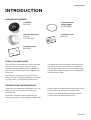
INTRODUCTION
B001225
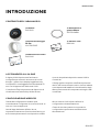
INTRODUCTION
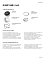
PACKAGING CONTENT
1x VMH 14
B001099
1x 52 mm Rubber
sealing gasket
A2C53194838
1x 52 mm Mounting
Spinlock
A2C52059471
1x Veratron card
B000101
1x
Safety manual
B000100
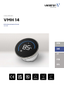
THE ALL-IN-ONE GAUGE
The VMH device can easily be configured to be
the instrument you need - thanks to its sun-
readable display embedded into a standard 52
mm instrument housing with the elegant VMH-
series look.
The EasyLink-Interface allows the device to
display a variety of different datatypes, received
from any VMH- or OceanLink master device.
The simple but effective graphic design presents
the data in a clear and intuitive form. In addition,
the round bar graph with the customizable range
and the alarm displays helps you to visually better
understand your data.
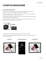
CONTACTLESS CONFIGURATION
Thanks to the contactless configuration you can
setup your all-in-one instrument with your
smartphone!
Launch the companion app and define your
settings through the user-friendly interface, then
simply hold your mobile device in proximity of the
VMH 14 device to transfer the configuration.
Thanks to the embedded passive antenna the
configuration can be done powerless!

SAFETY INFORMATION
B001225
SAFETY INFORMATION
WARNING
• No smoking! No open fire or heat sources!
• The product was developed, manufactured
and inspected according to the basic safety
requirements of EC Guidelines and state-of-
the-art technology.
• The instrument is designed for use in grounded
vehicles and machines as well as in pleasure
boats, including non-classified commercial
shipping.
• Use our product only as intended. Use of the
product for reasons other than its intended use
may lead to personal injury, property damage
or environmental damage. Before installation,
check the vehicle documentation for vehicle
type and any possible special features!
• Use the assembly plan to learn the location of
the fuel/hydraulic/compressed air and
electrical lines!
• Note possible modifications to the vehicle,
which must be considered during installation!
• To prevent personal injury, property damage or
environmental damage, basic knowledge of
motor vehicle/shipbuilding electronics and
mechanics is required.
• Make sure that the engine cannot start
unintentionally during installation!
• Modifications or manipulations to veratron
products can affect safety. Consequently, you
may not modify or manipulate the product!
• When removing/installing seats, covers, etc.,
ensure that lines are not damaged and plug-in
connections are not loosened!
• Note all data from other installed instruments
with volatile electronic memories.
SAFETY DURING INSTALLATION
• During installation, ensure that the product’s
components do not affect or limit vehicle
functions. Avoid damaging these components!
• Only install undamaged parts in a vehicle!
• During installation, ensure that the product
does not impair the field of vision and that it
cannot impact the driver’s or passenger’s head!
• A specialized technician should install the
product. If you install the product yourself,
wear appropriate work clothing. Do not wear
loose clothing, as it may get caught in moving
parts. Protect long hair with a hair net.
• When working on the on-board electronics, do
not wear metallic or conductive jewelry such as
necklaces, bracelets, rings, etc.
• If work on a running engine is required, exercise
extreme caution. Wear only appropriate work
clothing as you are at risk of personal injury,
resulting from being crushed or burned.
• Before beginning, disconnect the negative
terminal on the battery, otherwise you risk a
short circuit. If the vehicle is supplied by
auxiliary batteries, you must also disconnect
the negative terminals on these batteries!
Short circuits can cause fires, battery
explosions and damages to other electronic
systems. Please note that when you disconnect
the battery, all volatile electronic memories
lose their input values and must be
reprogrammed.
• If working on gasoline boat motors, let the
motor compartment fan run before beginning
work.
• Pay attention to how lines and cable harnesses
are laid so that you do not drill or saw through
them!
• Do not install the product in the mechanical
and electrical airbag area!
• Do not drill holes or ports in load-bearing or
stabilizing stays or tie bars!
• When working underneath the vehicle, secure
it according to the specifications from the
vehicle manufacturer.
• Note the necessary clearance behind the drill
hole or port at the installation location.
Required mounting depth: 65 mm.

SAFETY INFORMATION
B001225
• Drill small ports; enlarge and complete them, if
necessary, using taper milling tools, saber saws,
keyhole saws or files. Deburr edges. Follow the
safety instructions of the tool manufacturer.
• Use only insulated tools if work is necessary on
live parts.
• Use only the multimeter or diode test lamps
provided, to measure voltages and currents in
the vehicle/machine or boat. Use of
conventional test lamps can cause damage to
control units or other electronic systems.
• The electrical indicator outputs and cables
connected to them must be protected from
direct contact and damage. The cables in use
must have enough insulation and electric
strength and the contact points must be safe
from touch.
• Use appropriate measures to also protect the
electrically conductive parts on the connected
consumer from direct contact. Laying metallic,
uninsulated cables and contacts is prohibited.
SAFETY AFTER INSTALLATION
• Connect the ground cable tightly to the
negative terminal of the battery.
• Reenter/reprogram the volatile electronic
memory values.
• Check all functions.
• Use only clean water to clean the components.
Note the Ingress Protection (IP) ratings (IEC
60529).
ELECTRICAL CONNECTIONS
• Note cable cross-sectional area!
• Reducing the cable cross-sectional area leads
to higher current density, which can cause the
cable cross-sectional area in question to heat
up!
• When installing electrical cables, use the
provided cable ducts and harnesses; however,
do not run cables parallel to ignition cables or
to cables that lead to large electricity
consumers.
• Fasten cables with cable ties or adhesive tape.
Do not run cables over moving parts. Do not
attach cables to the steering column!
• Ensure that cables are not subject to tensile,
compressive or shearing forces.
• If cables are run through drill holes, protect
them using rubber sleeves or the like.
• Use only one cable stripper to strip the cable.
Adjust the stripper so that stranded wires are
not damaged or separated.
• Use only a soft soldering process or
commercially available crimp connector to
solder new cable connections!
• Make crimp connections with cable crimping
pliers only. Follow the safety instructions of the
tool manufacturer.
• Insulate exposed stranded wires to prevent
short circuits.
• Caution: Risk of short circuit if junctions are
faulty or cables are damaged.
• Short circuits in the vehicle network can cause
fires, battery explosions and damages to other
electronic systems. Consequently, all power
supply cable connections must be provided
with weldable connectors and be sufficiently
insulated.
• Ensure ground connections are sound.
• Faulty connections can cause short circuits.
Only connect cables according to the electrical
wiring diagram.
• If operating the instrument on power supply
units, note that the power supply unit must be
stabilized and it must comply with the following
standard: DIN EN 61000, Parts 6-1 to 6-4.

INSTALLATION
B001225
INSTALLATION
WARNING
Before beginning, disconnect the negative terminal on the battery, otherwise you risk a short circuit.
If the vehicle is supplied by auxiliary batteries, you must also disconnect the negative terminals on
these batteries! Short circuits can cause fires, battery explosions and damages to other electronic
systems. Please note that when you disconnect the battery, all volatile electronic memories lose their
input values and must be reprogrammed.
BEFORE THE ASSEMBLY
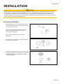
1.
Before beginning, turn off the ignition and
remove the ignition key. If necessary, remove
the main circuit switch.
Disconnect the negative terminal on the
battery. Make sure the battery cannot
unintentionally restart.
Refer to the safety instructions of this
document.
2.
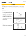
Place the device at least 300 mm away from
any magnetic compass.
3.
Consider that the device must be connected
to an VMH master device and/or other VMH
14 gauges (maximum 16 gauges in a daisy
chain per master).

INSTALLATION
B001225
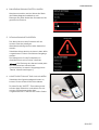
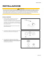
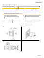
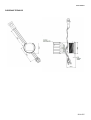
INSTALLATION WITH SPINLOCK
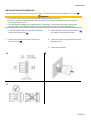
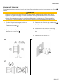
The panel width may be within a range of 1 to 12 mm. The drill hole must have a diameter of 52 mm [A].
WARNING
• Do not drill holes or ports in load-bearing or stabilizing stays or tie bars!
• Note the necessary clearance behind the drill hole or port at the installation location. Required
mounting depth: 40 mm.
• Drill small ports; enlarge and complete them, if necessary, using taper milling tools, saber saws,
keyhole saws or files. Deburr edges. Follow the safety instructions of the tool manufacturer.
1. Create a circular hole in the panel considering
the device dimensions. [A]
2. Remove the spinlock and insert the device
from the front. [B]
3. Adjust the spinlock as shown in picture [C]
according to the panel thickness.
4. Carefully screw in the spinlock by hand at
least two turns.
5. Insert the connector.
A B
C

CONNECTION
B001225
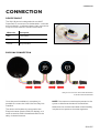
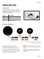
CONNECTION
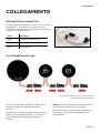
DEVICE PINOUT
The VMH 14
device is designed with two AMP
SuperSeal 1.5 connectors on the backside – one male
and one female – to allow the daisy-chain connection
of up to 16 instruments in series to the master.
Wire color Description
Red + 12V power
Blue Ground
Yellow EasyLink data
EASYLINK CONNECTION
EasyLink connection with VMH 35 master
and two VMH 14 satellites
Once the panel installation is complete it is
possible to connect the VMH 14 to the EasyLink
interface.
The device can be directly connected to the
EasyLink master (like the VMH 35 display), or in
series to another VMH 14 satellite thanks to the
daisy-chain architecture.
NOTE: One master must always be present in the
system to distribute the data to the satellites.
Make sure the contacts have been locked audibly
into place so to preserve the water tightness.

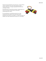
CONNECTION
B001225
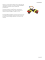
In case the length of the cable is not enough to reach the
next device, it is possible to extend the total length by using
the accessory EasyLink extension cable A2C59500139.
Please note that EasyLink does not allow daisy chains
longer than 20 meters and with maximum 16 satellite
devices.
It is recommended to connect the blind plug (provided with
the master instrument) after the last satellite instrument to
avoid water intrusion through the unused connector.

DISPLAY LAYOUT
B001225
DISPLAY LAYOUT
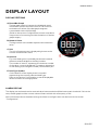
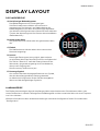
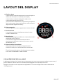
DISPLAY SECTIONS
A: Round Bar Graph
The bar graph helps to interpret the displayed vessel
information quicker and more intuitive. The minimum
and maximum values of the bar graph range are
customizable via the VMH14 App.
(Refer to the section Configurations to learn more about
the process of customizing and the limitations of the bar
graph ranges.)
B: Numeric Value
The big number in the middle represent the measured
value.
C: Unit
The unit of measurement is displayed right next to the
numeric measurement value.
D: Instance
For some data types it’s possible that there are several
different values available on the EasyLink bus.
The number in “area D” represents the instance number
of the value, currently displayed. This means, depending
on the data type, the engine number/ tank number/etc. .
E: Data Type Symbol
On the bottom of the display there is a symbol
representing the currently selected data type.
Refer to the section Configuration to see all displayable
values and their according symbols.
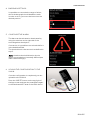
ALARM DISPLAY
The display can indicate that the received value has exceeded or fell below a certain threshold. If this is the
case, the bar graph and the numeric value will start to blink with a frequency of 1Hz.
More information about the alarm settings and how to configure them can be found in the section
“Configuration”.

CONFIGURATION
B001225
CONFIGURATION
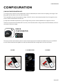
VMH 14 CONFIGURATOR APP
To configure the VMH 14, some parameters must be calibrated, like which value to display, the range of the
bar graph and the alarms such as their thresholds.
This is possible through the smartphone App “VMH 14”, which can be downloaded free of charge from the
stores of both Android and iOS devices.
A simple and detailed explanation of the configuration process is also available as in-app instructions.
Thanks to the passive embedded NFC receiver, the VMH 14 can be configured, as described below, without
the need of a power supply.
VMH 14
CONFIGURATOR
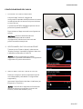
The setup of the VMH 14 device is an intuitive three-step process. Please remember that you must READ
from the device before being able to modify and download the configuration to the instrument.
1. READ
2. CONFIGURE
3. WRITE

CONFIGURATION
B001225
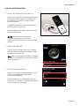
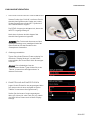
VMH 14 CONFIGURATION
1.
READ THE
VMH 14
CONFIGURATION
Launch the “VMH 14” App and read the current
configuration of the device by “tapping” the
smartphone onto the NFC symbol on the
devices rear side.
The READ operation is mandatory before the
WRITE operation is allowed.
After the readout, the App will be set with the
current configuration.
NOTE: The antenna position on the
smartphone depends on the model.
Please refer to the smartphone manufacturer
manual.
2. SELECT GAUGE TYPE
Tap the “Data to display” item in the “Display
Settings” section to choose the data you want
to display on the VMH 14.
Note: See the complete list of supported gauge
types in the “Supported Configurations” table
of this document.
3. SET UNITS AND INSTANCE
Define the unit for the displayed value if more
than one is available (see “Supported
Configurations” table).
Set the instance for the displayed value (e.g.
Engine No. or Tank No.) so that the VMH 14 will
show your data on the display.

CONFIGURATION
B001225
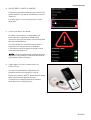
4. BARGRAPH SETTINGS
It’s possible to customize the range of values,
which the bar graph should be able to reach.
In order to do so, just move the levers into the
desired position.
5. CONFIGURE THE ALARM
The alarm can be activated or deactivated by
using the switches on the right side of the
according alarm description.
Once active, it is possible to set a threshold for it
in the dedicated field.
The threshold unit is the same unit as defined in
step 3.
Note: the alarm threshold direction (active
above or active below) is statically defined (see
table “Alarm Settings”).
6. UPLOAD THE CONFIGURATION TO THE
VMH 14
Once the configuration is completed, you can
upload it to the VMH 14.
Press the “WRITE” button on the top/right of
the App screen and near the smartphone again
to the dedicated NFC area of the VMH device.

CONFIGURATION
B001225
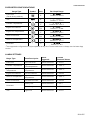
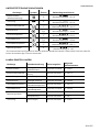
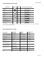
SUPPORTED CONFIGURATIONS
Gauge Type Symbol Unit Bar Graph Range
Fuel Level
(Set as factory default)
%
0
–
100 %
Default: 0 – 100 %
Trim
TRIM
%
0
–
100 %
Default: 0 – 100 %
Coolant Temperature
°C
°F
0
–
200 °C
Default: 40 – 120 °C
Engine Oil Pressure
bar
PSI
0
–
30 bar
Default: 0 – 10 bar
Engine Oil Temperature
°C
°F
0
–
200 °C
Default: 0 - 150°C
Gear Oil Pressure
bar
PSI
0
–
30 bar
Default: 0 – 25 bar
Gear Oil Temperature
°C
°F
0
–
200 °C
Default: 0 – 150 °C
Voltmeter
-
V
0
–
30 V
Default: 11 – 14 V
*
The supported configurations may be updated at any time. Please make sure to always use the latest App
version.
ALARM SETTINGS
Gauge Type Alarm Description
Alarm
triggered...
Possible
Threshold Values
Fuel Level Low Fuel Level below threshold 0 - 100 %
Coolant Temperature
Engine
Overtemperature above threshold 0 - 200 °C
Engine Oil
Temperature
High Oil
Temperature above threshold 0 - 200 °C
Engine Oil Pressure Low Oil Pressure below threshold 0 - 30 bar
Gear Oil Temperature
High Gear Oil
Temperature above threshold 0 - 200 °C
Gear Oil Pressure Low Gear Oil Press below threshold 0 - 30 bar
Voltmeter
Battery Low below threshold 0 - 30 V
Overvoltage above threshold 0 - 30 V
Trim Engine Tilt above threshold 0 - 100 %

TECHNICAL DATA
B001225
TECHNICAL DATA
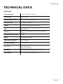
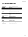
DATASHEET
Nominal Voltage 12 V (from EasyLink connection)
Connectivity EasyLink, NFC
Configuration interface NFC (Near Field Communication)
Protection class IP X7 acc. IEC60529
Display Optically bonded IBN segment display
Lens Mineral glass
Housing Ø52 mm – Polycarbonate (PC), flame retardant acc.
UL94-V0
Required mounting depth 40 mm
Bezels Brushed stainless steel
Operating temperature -20°C to +60°C
Storage temperature -30°C to +80°C
Connector
AMP SuperSeal 1.5
P/N Male: 282105-1
P/N Female: 282087-1
Mounting Spinlock Nut – locking height 0.5 – 20 mm
Certifications CE, UKCA, Reach, RoHS, UL94-V0

TECHNICAL DATA
B001225
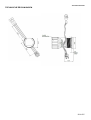
TECHNICAL DRAWINGS

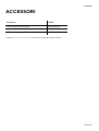
ACCESSORIES
B001225
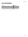
ACCESSORIES
Accessory Part Number
EasyLink Extension cable A2C59500139
Spinlock Nut 52 mm A2C52059471
52 mm Rubber sealing gasket A2C53194838
Visit http://www.veratron.com
for the complete list of accessories.

veratron AG
Industriestrasse 18
9464 Rüthi,
Switzerland
T +41 71 7679 111
veratron.com
Any distribution, translation or reproduction, partial or total, of the
document is strictly prohibited unless with prior authorization in
writing from veratron AG, except for the following actions:
• Printing the document in its original format, totally or partially.
• Copying contents without any modifications and stating Veratron
AG as copyright owner.
Veratron AG reserves the right to make modifications or
improvements to the relative documentation without notice.
Requests for authorization, additional copies of this manual or
technical information on the latter, must be addressed to veratron
AG.
Seite wird geladen ...
Seite wird geladen ...
Seite wird geladen ...
Seite wird geladen ...
Seite wird geladen ...
Seite wird geladen ...
Seite wird geladen ...
Seite wird geladen ...
Seite wird geladen ...
Seite wird geladen ...
Seite wird geladen ...
Seite wird geladen ...
Seite wird geladen ...
Seite wird geladen ...
Seite wird geladen ...
Seite wird geladen ...
Seite wird geladen ...
Seite wird geladen ...
Seite wird geladen ...
Seite wird geladen ...
Seite wird geladen ...
Seite wird geladen ...
Seite wird geladen ...
Seite wird geladen ...
Seite wird geladen ...
Seite wird geladen ...
Seite wird geladen ...
Seite wird geladen ...
Seite wird geladen ...
Seite wird geladen ...
Seite wird geladen ...
Seite wird geladen ...
Seite wird geladen ...
Seite wird geladen ...
Seite wird geladen ...
Seite wird geladen ...
Seite wird geladen ...
Seite wird geladen ...
-
 1
1
-
 2
2
-
 3
3
-
 4
4
-
 5
5
-
 6
6
-
 7
7
-
 8
8
-
 9
9
-
 10
10
-
 11
11
-
 12
12
-
 13
13
-
 14
14
-
 15
15
-
 16
16
-
 17
17
-
 18
18
-
 19
19
-
 20
20
-
 21
21
-
 22
22
-
 23
23
-
 24
24
-
 25
25
-
 26
26
-
 27
27
-
 28
28
-
 29
29
-
 30
30
-
 31
31
-
 32
32
-
 33
33
-
 34
34
-
 35
35
-
 36
36
-
 37
37
-
 38
38
-
 39
39
-
 40
40
-
 41
41
-
 42
42
-
 43
43
-
 44
44
-
 45
45
-
 46
46
-
 47
47
-
 48
48
-
 49
49
-
 50
50
-
 51
51
-
 52
52
-
 53
53
-
 54
54
-
 55
55
-
 56
56
-
 57
57
-
 58
58


in anderen Sprachen
- English: veratron VMH 14 User manual
- italiano: veratron VMH 14 Manuale utente
Verwandte Artikel

Andere Dokumente
-
Bosch Appliances BAUER VMH 300 Benutzerhandbuch
-
Mitsubishi Electric CITY MULTI PEFY-P80VMH-A-F Installationsanleitung
-
probst SH-3500-B Benutzerhandbuch
-
-
Yamaha DME32 Bedienungsanleitung
-
Carson Reflex Wheel Pro Bedienungsanleitung
-
VDO VIEWLINE 85 MM Bedienungsanleitung