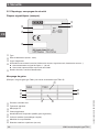
WIKA TR21-C Bedienungsanleitung
- Kategorie
- Digitale Körperthermometer
- Typ
- Bedienungsanleitung
Dieses Handbuch ist auch geeignet für

Operating instructions
Betriebsanleitung
Mode d‘emploi
Manual de instrucciones
EN
DE
FR
ES
Model TR21-A
Miniature resistance thermometer
For sanitary applications, model TR21
Miniatur-Widerstandsthermometer
Für die sterile Verfahrenstechnik, Typ TR21
Sonde à résistance miniature
Pour applications sanitaires, type TR21
Termorresistencia miniatura
Para procesos asépticos, modelo TR21
Model TR21-B Model TR21-C
70018194
JANUARY 2019
TYPE EL
CLASS I
®

2
14006814.09 03/2019 EN/DE/FR/ES
WIKA operating instructions model TR21
EN
DE
FR
ES
Operating instructions model TR21
Page
3 - 30
Betriebsanleitung Typ TR21
Seite
31 - 58
Mode d‘emploi type TR21
Page
59 - 86
Manual de instrucciones modelo TR21
Página
87 - 114
© 05/2011 WIKA Alexander Wiegand SE & Co. KG
All rights reserved. / Alle Rechte vorbehalten.
WIKA
®
is a registered trademark in various countries.
WIKA
®
ist eine geschützte Marke in verschiedenen Ländern.
Prior to starting any work, read the operating instructions!
Keep for later use!
Vor Beginn aller Arbeiten Betriebsanleitung lesen!
Zum späteren Gebrauch aufbewahren!
Lire le mode d‘emploi avant de commencer toute opération !
A conserver pour une utilisation ultérieure !
¡Leer el manual de instrucciones antes de comenzar cualquier trabajo!
¡Guardar el manual para una eventual consulta!

14006814.09 03/2019 EN/DE/FR/ES
WIKA operating instructions model TR21 3
EN
1. General information 4
2. Design and function 4
3. Safety 7
4. Transport, packaging and storage 11
5. Commissioning, operation 12
6. Additional notes for instruments with EHEDG and 3-A 16
7. Configuration 17
8. Configuration software WIKAsoft-TT 18
9. Connecting the PU-548 programming unit 20
10. Faults 20
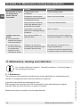
11. Maintenance, cleaning and calibration 22
12. Dismounting, return and disposal 24
13. Specifications 25
Appendix: CSA control drawing 30
Declarations of conformity can be found online at www.wika.com.
Contents
Contents

14006814.09 03/2019 EN/DE/FR/ES
WIKA operating instructions model TR214
EN
1. General information
■
The miniature resistance thermometers described in the operating instructions have
been manufactured using state-of-the-art technology.
■
These operating instructions contain important information on handling the instrument.
Working safely requires that all safety instructions and work instructions are observed.
■
Observe the relevant local accident prevention regulations and general safety
regulations for the instrument’s range of use.
■
Skilled personnel must have carefully read and understood the operating instructions
prior to beginning any work.
■
Subject to technical modifications.
■
Further information:
- Internet address: www.wika.de / www.wika.com
- Application consultant:
Tel.: +49 9372 132-0
Fax: +49 9372 132-406
info@wika.de
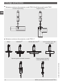
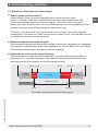
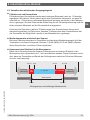
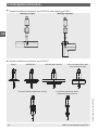
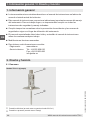
2. Design and function
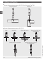
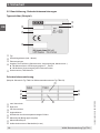
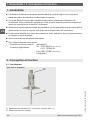
2.1 Overview
Electrical connection (here: M12 x 1 circular connector)
Process connection (here: Clamp)
Model TR21-C (example)
1. General information / 2. Design and function

14006814.09 03/2019 EN/DE/FR/ES
WIKA operating instructions model TR21 5
EN
2.2 Description
The model TR21 miniature resistance thermometers consist of a temperature sensor and a
thermowell with a hygienic process connection.
Any change in the temperature causes a change in the resistance of the sensor in the
temperature sensor. This change can be measured directly or can, optionally, be converted
into a 4 ... 20 mA signal proportional to the temperature.
The thermowell is used to adapt the thermometer to the process and protects the sensor
against harsh process conditions. Furthermore, the detachable connection from the
thermowell in the TR21-A and TR21-B variants enables the removal of the temperature
sensor without having to open the process. In this way, any hygienic risk is minimised
and it is possible to calibrate the entire measuring chain (sensor, transmitter if required,
connection cable) on site, without having to disconnect the electrical connections.
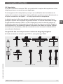
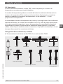
Overview of the process connections, thermowell variants
■
Miniature resistance thermometer, model TR21-A with thermowell model TW22
+
VARIVENT
®
DIN 11851/DIN 11864Clamp BioControl
®
Process connection, straight Ball-/Collar-type
compression fitting
Welding ballUnion nut SMS
2. Design and function

14006814.09 03/2019 EN/DE/FR/ES
WIKA operating instructions model TR216
EN
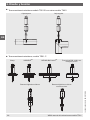
■
Miniature resistance thermometer, model TR21-B with thermowell model TW61
■
Miniature resistance thermometer, model TR21-C
Flow-through housing Angular housing
Clamp VARIVENT
®
NEUMO BioControl
®
Tapered hygienic threaded connection Tapered hygienic threaded
connection with union nut
Union nut DIN 11851 with
conical coupling
2. Design and function

14006814.09 03/2019 EN/DE/FR/ES
WIKA operating instructions model TR21 7
EN
This document describes standard versions of instruments. For applications in hazardous
areas special instrument designs are required.
For further information for operation in hazardous areas, see the additional information for
the corresponding ignition protection type (separate document).
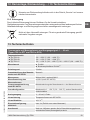
2.3 Scope of delivery
Cross-check scope of delivery with delivery note.
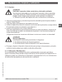
3. Safety
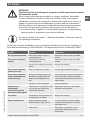
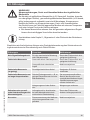
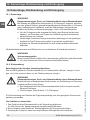
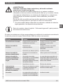
3.1 Explanation of symbols
WARNING!
... indicates a potentially dangerous situation that can result in serious injury
or death, if not avoided.
CAUTION!
... indicates a potentially dangerous situation that can result in light injuries or
damage to property or the environment, if not avoided.
DANGER!
... identifies hazards caused by electrical power. Should the safety
instructions not be observed, there is a risk of serious or fatal injury.
WARNING!
... indicates a potentially dangerous situation that can result in burns, caused
by hot surfaces or liquids, if not avoided.
Information
... points out useful tips, recommendations and information for efficient and
trouble-free operation.
2. Design and function / 3. Safety

14006814.09 03/2019 EN/DE/FR/ES
WIKA operating instructions model TR218
EN
3.2 Intended use
The model TR21 resistance thermometer has been specifically designed for the
measurement of temperatures in vessels or pipes, in the range of -30 … +150 °C
(-22 ... +302 °F) or -30 … +250 °C (-22 ... +482 °F), which are used in sanitary applications.
Here, the thermowell is used to protect the temperature sensor from the process
conditions. Furthermore, the detachable connection from the thermowell in the TR21-A
and TR21-B variants enables the removal of the temperature sensor without having to shut
down the process; and thus guards against any damage to the environment or to personnel
which might be caused by escaping process media.
Neither repairs nor structural modifications are permitted, and any would void the
guarantee and the respective certification. The manufacturer shall not be responsible for
constructional modifications after delivery of the instruments.
The instrument has been designed and built solely for the intended use described here,
and may only be used accordingly.
The technical specifications contained in these operating instructions must be observed.
Improper handling or operation of the instrument outside of its technical specifications
requires the instrument to be taken out of service immediately and inspected by an
authorised WIKA service engineer.
The manufacturer shall not be liable for claims of any type based on operation contrary to
the intended use.
3.3 Responsibility of the operator
The system operator is responsible for selecting the thermometer or thermowell, and for
the selection of their materials, so as to guarantee their safe operation within the plant or
machine. When preparing a quote, WIKA can only give recommendations which are based
on our experience in similar applications.
The safety instructions within these operating instructions, as well as the safety, accident
prevention and environmental protection regulations for the application area must be
maintained.
The operator is obliged to maintain the product label in a legible condition.
3. Safety

14006814.09 03/2019 EN/DE/FR/ES
WIKA operating instructions model TR21 9
EN
3.4 Personnel qualification
WARNING!
Risk of injury should qualification be insufficient
Improper handling can result in considerable injury and damage to
equipment.
▶
The activities described in these operating instructions may only be
carried out by skilled electrical personnel who have the qualifications
described below.
Skilled electrical personnel
Skilled electrical personnel are understood to be personnel who, based on their technical
training, know-how and experience as well as their knowledge of country-specific
regulations, current standards and directives, are capable of carrying out work on
electrical systems and independently recognising and avoiding potential hazards. The
skilled electrical personnel have been specifically trained for the work environment they
are working in and know the relevant standards and regulations. The skilled electrical
personnel must comply with current legal accident prevention regulations.
Operating personnel
The personnel trained by the operator are understood to be personnel who, based on their
education, knowledge and experience, are capable of carrying out the work described and
independently recognising potential hazards.
Special operating conditions require further appropriate knowledge, e.g. of aggressive
media.
3. Safety

14006814.09 03/2019 EN/DE/FR/ES
WIKA operating instructions model TR2110
EN
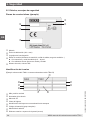
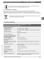
3.5 Labelling, safety marks
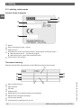
Product labels (example)
Model
Date of manufacture (year - month)
Approval logos
Information on version (measuring element, output signal, measuring range...)
■
With transmitter and 4 … 20 mA output signal
■
With direct sensor output with Pt100 and Pt1000
Serial number, TAG number
Thermowell marking
(Example: Model TW61 thermowell for model TR21-B resistance thermometer)
Max. nominal pressure
Pipe standard
CE mark
Hygiene class
Identification of the qualified inspector (for stamping)
Material code (complete assembly)
Tubular body material
Outer diameter x wall thickness (in mm)
3. Safety

14006814.09 03/2019 EN/DE/FR/ES
WIKA operating instructions model TR21 11
EN
Before mounting and commissioning the instrument, ensure you
read the operating instructions!
4. Transport, packaging and storage
4.1 Transport
Check the instrument for any damage that may have been caused by transport.
Obvious damage must be reported immediately.
CAUTION!
Damage through improper transport
With improper transport, a high level of damage to property can occur.
▶
When unloading packed goods upon delivery as well as during internal
transport, proceed carefully and observe the symbols on the packaging.
▶
With internal transport, observe the instructions in chapter 4.2 “Packaging
and storage”.
If the instrument is transported from a cold into a warm environment, the formation of
condensation may result in instrument malfunction. Before putting it back into operation,
wait for the instrument temperature and the room temperature to equalise.
4.2 Packaging and storage
Do not remove packaging until just before mounting.
Permissible conditions at the place of storage:
Storage temperature: -40 ... +85 °C (-40 ... +185 °F)
Humidity: 5 ... 95 % r. h.
Avoid exposure to the following factors:
■
Direct sunlight or proximity to hot objects
■
Mechanical vibration, mechanical shock (putting it down hard)
■
Soot, vapour, dust and corrosive gases
■
Hazardous environments, flammable atmospheres
Store the instrument in its original packaging in a location that fulfils the conditions listed
above. If the original packaging is not available, pack and store the instrument as described
below:
1. Place the instrument, along with shock-absorbent material, in the packaging.
2. If stored for a prolonged period of time (more than 30 days), place a bag containing a
desiccant inside the packaging.
3. Safety / 4. Transport, packaging and storage

14006814.09 03/2019 EN/DE/FR/ES
WIKA operating instructions model TR2112
EN
5. Commissioning, operation
When using a thermowell additionally observe the information of the attached
thermowell operating instructions.
Maximum permissible temperatures:
■
At the case with transmitter: 85 °C (185 °F)
■
Temperature at the connector: max. 85 °C (185 °F)
■
Model TR21-A:
-30 ... +250 °C (-22 ... +482 °F)
■
Model TR21-B:
-30 ... +150 °C (-22 ... +302 °F)
■
Model TR21-C:
-30 ... +150 °C (-22 ... +302 °F)
-30 ... +250 °C (-22 ... +482 °F)
5.1 Mounting
The connection dimensions of the thermowell must match those of the counterpart on the
process side. Insert the thermowell into the process adapter without forcing or damaging it.
For sealing, choose appropriate seals. (for further information on mounting the thermowell,
see enclosed operating instructions for thermowells)
For installation, the appropriate fastenings, such as screws and nuts, must be used and
mounted using the appropriate tightening torques and tools (e.g. open-ended spanner).
The seals installed must be checked regularly that they are functioning correctly.
The corresponding parts on the process side, the seals and the sealing rings are not
included in the delivery.
The insertion length, along with the flow rate and viscosity of the process media, may
reduce the max. loading on the thermowell.
The case must be grounded against electromagnetic fields and electrostatic charge. It
is not necessary to connect the case separately to the equipotential bonding system,
provided that it has a fixed and secure contact to the metallic vessel, its components or
pipes, and that these are connected to the equipotential bonding system.
When there is a non-metallic contact with the vessel, or with its structural components or
piping, the instrument must be provided with equipotential bonding.
5. Commissioning, operation

14006814.09 03/2019 EN/DE/FR/ES
WIKA operating instructions model TR21 13
EN
5.1.1 Tightening torque for the M12 mating connector or the M12 adapter
Select a tightening torque of 0.6 Nm.
5.1.2 Tightening torque for union nut
Select a tightening torque of 15 Nm.
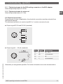
5.2 Electrical connection
Depending on the type of application, the electrical connection must be protected from
mechanical damage.
The electrical connection is made via an M12 x 1 circular connector (4-pin).
■
Output signal Pt100 and Pt1000 (standard)
■
Output signal 4 ... 20 mA (standard)
Alternative pin assignments possible. For further information see order documentation.
Pin Signal Description
1 L+ 10 ... 30 V
2 VQ not connected
3 L- 0V
4 C not connected
5. Commissioning, operation

14006814.09 03/2019 EN/DE/FR/ES
WIKA operating instructions model TR2114
EN
DANGER!
Danger to life caused by electric current
Upon contact with live parts, there is a direct danger to life.
▶
The instrument may only be installed and mounted by skilled personnel.
▶
Operation using a defective power supply unit (e.g. short circuit from the
mains voltage to the output voltage) can result in life-threatening voltages
at the instrument!
▶
Carry out mounting work only with power disconnected.
This is protection class 3 equipment for connection at low voltages, which are separated
from the power supply or voltages of greater than AC 50 V or DC 120 V. Preferably, a
connection to an SELV or PELV circuit is recommended; alternatively protective measures
from HD 60346-4-41 (DIN VDE 0100-410).
Alternatively for North America
The connection can be made in line with “Class 2 Circuits” or “Class 2 Power Units” in
accordance with CEC (Canadian Electrical Code) or NEC (National Electrical Code).
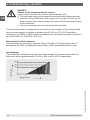
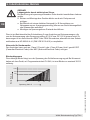
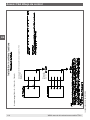
Load diagram
The permissible load depends on the loop supply voltage. For communication with the
instrument with programming unit PU-548, a max. load of 350 Ω is admissible.
0 10 24 30 36
1083
833
583
Load R
A
in Ω
Voltage U
B
in V
5. Commissioning, operation

14006814.09 03/2019 EN/DE/FR/ES
WIKA operating instructions model TR21 15
EN
Error
signalling
Error signalling
Error signalling
3.8 ...
4 mA
20 ... 20.5 mA
4 ... 20 mA
3.8 mA 4 mA 20 mA 20.5 mA
3.9 mA 20.4 mA
Error
signalling
Measuring mode
Error limits and permissible measuring range
5.3 Behaviour of the electrical output signal
■
Sensor break and short circuit
Sensor break or short circuit are signalled after positive detection (after
approx. 1 second). If this fault condition has been caused by a malfunction, then
a relevant measuring signal must exist for approx. 1 second in order to return to
measuring mode. From the time of the error detection up to the error signalling, the last
relevant measured value will be delivered on the current loop.
Therefore, in the event of a “true” sensor break or short circuit, this is also signalled
permanently. In the event of a “false” sensor break or short circuit, the transmitter has the
possibility of reverting to measuring mode.
■
Medium temperature outside the span
If the medium temperature exceeds that configured within the transmitter, the transmitter
will operate in a linear fashion within the following limits: 3.8 mA (MRS); 20.5 mA (MRE).
If these limits are exceeded, then an error will be signalled.
■
Hysteresis on return to the measuring span
After the linear error limits have been exceeded, on return to the measuring span, a
hysteresis of 0.1 mA must be passed. This hysteresis prevents the transmitter from
jumping back and forth between error and measuring mode.
5. Commissioning, operation

14006814.09 03/2019 EN/DE/FR/ES
WIKA operating instructions model TR2116
EN
6. Additional notes for instruments with EHEDG and 3-A
6.1 Compliance with the conformity in accordance with 3-A
For a 3-A compliant connection for milk thread fittings per DIN 11851, suitable profile
sealings have to be used (e.g. SKS Komponenten BV or Kieselmann GmbH).
Note:
To maintain the 3-A certification, one of the 3A-approved process connections must be
used. These are marked with the logo in the data sheet.
6.2 Compliance with EHEDG conformity
For an EHEDG conform connection, sealings in accordance with the current EHEDG policy
document must be used.
Manufacturers of sealings
■
Sealings for connections per ISO 2852, DIN 32676 and BS 4825 part 3:
e.g. Combifit International B.V.
■
Sealings for connections per DIN 11851: e.g. Kieselmann GmbH
■
VARIVENT
®
sealings: e.g. GEA Tuchenhagen GmbH
6.3 Mounting instructions
Observe the following instructions, especially for EHEDG certified and 3-A conform
instruments.
■
To maintain the EHEDG certification, one of the EHEDG-recommended process
connections must be used. These are marked with the logo in the data sheet.
■
To maintain the conformity to the 3-A standard, a 3-A conform process connection must
be used. These are marked with the logo in the data sheet.
■
Mount the electrical thermometer including thermowell with minimal dead space and
able to be cleaned easily.
■
The mounting position of the electrical thermometer including thermowell, welding
socket and instrumentation T-piece should be designed to be self-draining.
■
The mounting position must not form a draining point or cause a basin to be formed.
6.4 Cleaning in place (CIP) cleaning process
■
Only use cleaning agents which are suitable for the seals used.
■
Cleaning agents must not be abrasive nor corrosively attack the materials of the wetted
parts.
■
Avoid thermal shocks or fast changes in the temperature. The temperature difference
between the cleaning agent and rinsing with clear water should be as low as possible.
Negative example: Cleaning with 80 °C and rinsing at +4 °C with clear water.
6. Additional notes for instruments with EHEDG and 3-A

14006814.09 03/2019 EN/DE/FR/ES
WIKA operating instructions model TR21 17
EN
7. Configuration
Configuration is carried out using a USB interface with a PC via the model PU-548
programming unit (accessories, order No. 14231581). The connection with the
thermometer is made via the appropriate adapter cable (accessories: M12 x 1 circular
connector, order No. 14003193).
Measuring range, damping, error signalling, TAG No. and other parameters can be
adjusted (see configuration software).
The measuring range is configurable between -50 ... +250 °C (-58 ... +482 °F). The
configuration software checks the required measuring range and will only accept
permissible values. Intermediate values are configurable - the smallest increment is 0.1 °C
or 0.1 °F. The thermometers are delivered configured to customer specifications within the
configurable limits.
Please note:
The measuring range of the thermometer is limited by the application range of the
measuring element, not by the setting range of the transmitter.
Maximum permissible temperatures:
■
At the case with transmitter: 85 °C (185 °F)
■
Temperature at the connector: max. 85 °C (185 °F)
■
Model TR21-A:
-30 ... +250 °C (-22 ... +482 °F)
■
Model TR21-B:
-30 ... +150 °C (-22 ... +302 °F)
■
Model TR21-C:
-30 ... +150 °C (-22 ... +302 °F)
-30 ... +250 °C (-22 ... +482 °F)
■
Easy to use
■
LED status display
■
Compact design
■
No further power supply is needed for either the
programming unit or for the transmitter
(replaces programming unit model PU-448)
7. Configuration

14006814.09 03/2019 EN/DE/FR/ES
WIKA operating instructions model TR2118
EN
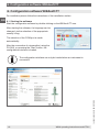
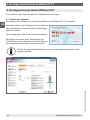
8. Configuration software WIKAsoft-TT
For installation please follow the instructions of the installation routine.
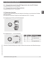
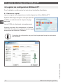
8.1 Starting the software
Start the configuration software by double-clicking on the WIKAsoft-TT icon.
After starting the software, the language can be
changed, via the selection of the appropriate
country‘s flag.
The selection of the COM port is made
automatically.
After the connection of a transmitter (using the
PU-548), on pressing the “Start” button, the
configuration interface is loaded.
The configuration interface can only be loaded when an instrument is
connected.
8. Configuration software WIKAsoft-TT

14006814.09 03/2019 EN/DE/FR/ES
WIKA operating instructions model TR21 19
EN
8.2 Configuration procedure
Steps 1 and 2 are carried out automatically when starting the software.
1. “Loading the instrument data”
2. “Loading configuration”
3. [optional] Cancel write protection (“key” symbol at the bottom right)
4. Change the required parameters
→ Sensor/Measuring range/Error signalling etc.
5. “Save to the instrument”
6. [optional] Activate write protection
7. [optional] Print configuration protocol
8. [optional] Test: “Loading configuration” → checking the configuration
8.3 Fault diagnosis
Here, in the event of an “error detected by the transmitter”, the error message is displayed.
Examples: Sensor break, permitted highest temperature exceeded, etc.
In normal operation, “No fault - No maintenance requirement” is displayed here.
8.4 Measured values
Line recorder - Here the measured value progression is represented in the format of a
chart recorder with a constant sampling rate in a defined time interval (180 seconds) and a
variable temperature axis.
The display purely serves as a functional check and for information.
An export of the data is not possible.
8.5 Configure several instruments identically
■
First instrument
1. “Loading configuration”
2. [optional] Cancel write protection (“key” symbol at the bottom right)
3. Change the required parameters
4. “Save to the instrument”
5. [optional] Activate write protection
■
All subsequent instruments
1. “Loading the instrument data”
2. [optional] Cancel write protection
3. [optional] Change the required parameters, e. g. TAG number
4. “Save to the instrument”
5. [optional] Activate write protection
For further information see chapter 1 “General information” “Contact data” or the
back page of these operating instructions.
8. Configuration software WIKAsoft-TT

14006814.09 03/2019 EN/DE/FR/ES
WIKA operating instructions model TR2120
EN
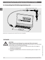
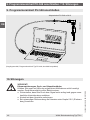
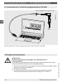
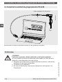
9. Connecting the PU-548 programming unit
(predecessor, programming unit model PU-448, also compatible)
10. Faults
CAUTION!
Physical injuries and damage to property and the environment
If faults cannot be eliminated by means of the listed measures, the instrument
must be taken out of operation immediately.
▶
Ensure that pressure or signal is no longer present and protect against
accidental commissioning.
▶
Contact the manufacturer.
▶
If a return is needed, please follow the instructions given in chapter 12.2
“Return”.
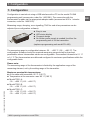
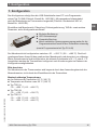
14004919.01
Adapter cable PU-548 to M12
TR21
9. Connecting the PU-548 programming unit / 10. Faults
Seite laden ...
Seite laden ...
Seite laden ...
Seite laden ...
Seite laden ...
Seite laden ...
Seite laden ...
Seite laden ...
Seite laden ...
Seite laden ...
Seite laden ...
Seite laden ...
Seite laden ...
Seite laden ...
Seite laden ...
Seite laden ...
Seite laden ...
Seite laden ...
Seite laden ...
Seite laden ...
Seite laden ...
Seite laden ...
Seite laden ...
Seite laden ...
Seite laden ...
Seite laden ...
Seite laden ...
Seite laden ...
Seite laden ...
Seite laden ...
Seite laden ...
Seite laden ...
Seite laden ...
Seite laden ...
Seite laden ...
Seite laden ...
Seite laden ...
Seite laden ...
Seite laden ...
Seite laden ...
Seite laden ...
Seite laden ...
Seite laden ...
Seite laden ...
Seite laden ...
Seite laden ...
Seite laden ...
Seite laden ...
Seite laden ...
Seite laden ...
Seite laden ...
Seite laden ...
Seite laden ...
Seite laden ...
Seite laden ...
Seite laden ...
Seite laden ...
Seite laden ...
Seite laden ...
Seite laden ...
Seite laden ...
Seite laden ...
Seite laden ...
Seite laden ...
Seite laden ...
Seite laden ...
Seite laden ...
Seite laden ...
Seite laden ...
Seite laden ...
Seite laden ...
Seite laden ...
Seite laden ...
Seite laden ...
Seite laden ...
Seite laden ...
Seite laden ...
Seite laden ...
Seite laden ...
Seite laden ...
Seite laden ...
Seite laden ...
Seite laden ...
Seite laden ...
Seite laden ...
Seite laden ...
Seite laden ...
Seite laden ...
Seite laden ...
Seite laden ...
Seite laden ...
Seite laden ...
Seite laden ...
Seite laden ...
Seite laden ...
Seite laden ...
-
 1
1
-
 2
2
-
 3
3
-
 4
4
-
 5
5
-
 6
6
-
 7
7
-
 8
8
-
 9
9
-
 10
10
-
 11
11
-
 12
12
-
 13
13
-
 14
14
-
 15
15
-
 16
16
-
 17
17
-
 18
18
-
 19
19
-
 20
20
-
 21
21
-
 22
22
-
 23
23
-
 24
24
-
 25
25
-
 26
26
-
 27
27
-
 28
28
-
 29
29
-
 30
30
-
 31
31
-
 32
32
-
 33
33
-
 34
34
-
 35
35
-
 36
36
-
 37
37
-
 38
38
-
 39
39
-
 40
40
-
 41
41
-
 42
42
-
 43
43
-
 44
44
-
 45
45
-
 46
46
-
 47
47
-
 48
48
-
 49
49
-
 50
50
-
 51
51
-
 52
52
-
 53
53
-
 54
54
-
 55
55
-
 56
56
-
 57
57
-
 58
58
-
 59
59
-
 60
60
-
 61
61
-
 62
62
-
 63
63
-
 64
64
-
 65
65
-
 66
66
-
 67
67
-
 68
68
-
 69
69
-
 70
70
-
 71
71
-
 72
72
-
 73
73
-
 74
74
-
 75
75
-
 76
76
-
 77
77
-
 78
78
-
 79
79
-
 80
80
-
 81
81
-
 82
82
-
 83
83
-
 84
84
-
 85
85
-
 86
86
-
 87
87
-
 88
88
-
 89
89
-
 90
90
-
 91
91
-
 92
92
-
 93
93
-
 94
94
-
 95
95
-
 96
96
-
 97
97
-
 98
98
-
 99
99
-
 100
100
-
 101
101
-
 102
102
-
 103
103
-
 104
104
-
 105
105
-
 106
106
-
 107
107
-
 108
108
-
 109
109
-
 110
110
-
 111
111
-
 112
112
-
 113
113
-
 114
114
-
 115
115
-
 116
116


WIKA TR21-C Bedienungsanleitung
- Kategorie
- Digitale Körperthermometer
- Typ
- Bedienungsanleitung
- Dieses Handbuch ist auch geeignet für
in anderen Sprachen
- français: WIKA TR21-C Mode d'emploi
- español: WIKA TR21-C Instrucciones de operación
Verwandte Papiere
-
WIKA TGS55 tag:model:TGS73 Bedienungsanleitung
-
-
-
-
-
-
-
-
-
Sonstige Unterlagen
-
SICK TSP Bedienungsanleitung
-
 ALLDOCK ALLDOCK MEDIUM Assembly Instructions Manual
-
-
Alphacool Eisblock XPX Pro AM 4 Schnellstartanleitung
-
AKO AKO-80004A Converter Benutzerhandbuch
-
Baumer ZPH3-5254 Installationsanleitung
-
 autosen AA001 Mounting instructions
-
Zoofari ZTB 1500 A1 Bedienungsanleitung

