Yamaha MA2030a Bedienungsanleitung
- Kategorie
- Zusätzliche Musikausrüstung
- Typ
- Bedienungsanleitung
Dieses Handbuch eignet sich auch für

49 5 4 5
2 3 2 3 1
0
7
,
8
6 A B D E G
C F
H
L K
I
,
J
MJ
First, please carefully read the “IMPORTANT SAFETY INSTRUCTIONS” on the reverse side.
Thank you for your purchase of the Yamaha MA2120 power amplifier. Please read through this manual
carefully before beginning use, so that you will be able to take full advantage of the device’s various
functions. After you have read the manual, keep it in a safe place.
• The illustrations as shown in this manual are for instructional purposes only.
• The company names and product names in this manual are the trademarks or registered trademarks of
their respective companies.
Features
• Complies with the ENERGY STAR international standard for energy efficient products.
• Supports both high-impedance and low-impedance speaker connections.
• Mixing/Routing function allows you to mix various sources and to output to one stereo channel, or two
mono channels. Source and volume zoning capability for two zones in mono connection.
• Equipped with an auto-wake function that turns the power on after detecting an input signal when in
standby mode.
• Various digital signal processing and effects, including reverb, compressor, EQ, leveler, ducker and
feedback suppressor.
• Built-in “Speaker EQ” that allows for tuning the sound quality to be perfect for use with Yamaha
speakers.
• Remote controllable with up to two DCP control panels.
Accessories (Please confirm that all items are included)
• Power cord
• Euroblock plugs (6-pin x 3, 3-pin x 1, both with a 3.5mm pitch)
• Setup Guide
• Owner’s Manual (this sheet)
About Manuals
Owner’s Manual (this leaflet)
Explains about precautions, controls and functions on the panel, attaching Euroblock plugs, connecting
speaker cables, and connecting external devices.
Setup Guide (separated)
Provides setup examples, explains settings to make after installation, and connecting control panels and
remote controller.
ENERGY STAR Certification
This device complies with the ENERGY STAR international standard for energy
efficient products.
It automatically enters into standby mode when no input signal is detected for 25
minutes in order to save power while not in use.
In addition, a highly efficient amplifier circuitry design has been adopted to reduce
energy consumption while the device is in use.
Auto-Standby and Auto-Wake Functions
To reduce energy consumption, this device enters into standby mode when no input signal is detected for
25 minutes.
It is also equipped with an auto-wake function that automatically turns the power on when an input signal
is detected while in standby mode. Even when the device has been put into standby mode by the auto-
standby function, any microphone or BGM audio input will restore the power.
The auto-wake function is turned on by default. The auto-wake function can be turned on or off by
changing the rear panel [SETUP] DIP switch setting. (Refer to “Controls and Functions.”)
Setup Example
■
When multiple speakers are connected to the two zones:
(MODE: MONO)
BMG source
DCP (for zone A)
DCP (for zone B) Zone B: 7.5W x 10 = 75W
Zone A: 15W x 6 = 90W
■
When two-channel stereo is used:
(MODE: STEREO)
BMG source DCP 120W x 2 (two-channel stereo)
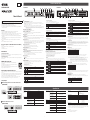
1
[z] button (Standby/On)
Switches the device mode between standby and on.
On: Press the [z] button when in standby mode. The button lights in green to indicate that the device is on.
Standby: Press and hold the [z] button for at least one second when the device is on. The button lights in orange to
indicate that the device is in standby mode.
The button lights in lime green for a few seconds while the status is switched between on and standby.
NOTE
• The device automatically enters standby mode when no input signal is detected for 25 minutes. The rear panel DIP
switch can be set to enable the auto-wake function that turns the power on upon detecting an input signal.
• Rapidly turning the unit on and off in succession can cause it to malfunction. After turning the unit off, wait for about 6
seconds before turning it on again.
2
[VOLUME A] and [VOLUME B] knobs
Used to adjust [SPEAKER A] and [SPEAKER B] output levels.
3
[BASS] and [TREBLE] controls
Two-band equalizer used to adjust the tone of the output signal to [SPEAKER A] and [SPEAKER B].
They can be adjusted with a tool such as a screwdriver.
4
[SIG] indicator
Lights up when the output signal to [SPEAKER A] or [SPEAKER B] is -42dBFS (42dB lower than the maximum output)
or higher.
5
[LIMIT] indicator
Lights up when the limiter that prevents excessive output to [SPEAKER A] and [SPEAKER B] compresses the signal
more than 3dB, for example. Adjust the input and output levels as LIMIT indicators do not light.
6
Input level knobs 1 - 8
Adjusts the input levels for [INPUT 1] - [INPUT 8]. Turning to the right increases the input level. In usual mode, press the
knob to blink the [SIG] indicator of the output which the pressed channel is assigned to. You can confirm the selected
output by the [ROUTE] switch of the rear panel.
In setup mode, press the knob to select the function to adjust, or to select a channel for adjustment.
For more information regarding setup mode, refer to the “Setup Guide”.
7
[INPUT SIG] indicators 1 - 8
Light up when the [INPUT 1] - [INPUT 8] input signal levels exceed -40dBFS.
Adjust the input levels to a point where these indicators light by the input level knobs.
8
[INPUT PEAK] indicators 1 - 8
Light up when the [INPUT 1] - [INPUT 8] input signal levels exceed -3dBFS.
9
[AUX IN] jack
Input jack of mini-stereo type (unbalanced input). Connect a stereo audio source such as portable audio players.
The signal from the [AUX IN] jack mixes with the signal from the [INPUT] jack 8 in the same signal path.
0
[SETUP] encoder/indicators 1 - 3
Push encoders for the various inbuilt adjustment functions. Press and hold this button to enter setup mode.
Indicators 1 - 3 show adjustment values for setup mode functions.
For more information regarding setup mode, refer to the “Setup Guide”.
A
AC IN connector
Connect the supplied power cord.
Caution
• When connecting the power cord, connect the power cord to the connector and then plug it into an appropriate AC power
outlet.
• Before connecting or disconnecting the power cord, make sure that the device power is in standby mode.
B
[SETUP] DIP switches
Set the following functions of the device. The setting change will be applied after carrying out a power cycle by
pressing the [z] button on the front panel.
DIP switch setting combinations are shown as follows.
DIP switches 1/2: Panel lock
Set knobs and controls to be locked on the panel.
1 2 Setting
Panel lock off (All controls are enabled)
Locks the [SETUP] knob
Locks controls other than [VOLUME] knobs
Panel lock on (All controls are disabled)
DIP switches 3/ 4: Auto-wake
Enable the function where the device automatically turns on from standby mode upon detection of an input signal.
3 4 Setting
Auto-wake function on
Auto-wake function on. Only when the system is switched from AC off to standby mode due to insertion of the
AC plug, or put into standby mode by the auto-standby function.
Auto-wake function off
NOTE The auto-wake function is completely disabled if the device has been put into standby mode through operation via the
[REMOTE] connector.
DIP switch 5: A - B volume link
Sets whether SPEAKER A and SPEAKER B volume is linked.
When the link function is on, use the [VOLUME A] knob to control the volume.
5 Setting
Link off (SPEAKER A and SPEAKER B volume levels are independently controlled)
Link on (SPEAKER A and SPEAKER B volume levels are both controlled via the [VOLUME A] knob)
NOTE If you turn on “A - B volume link” when the function to allow control of the line out volume A and B by the [VOLUME] knob
is enabled in setup mode, LINE OUT A and B are also linked.
DIP switch 6: DCP volume link
Sets whether the [SPEAKERS] and [LINE OUT] jack output levels are linked, when changing the volume via the DCP.
6 Setting
Link off ([SPEAKERS] and [LINE OUT] jack volume levels are controlled separately)
Link on ([SPEAKERS] and [LINE OUT] jack output is controlled together)
NOTE When the link function is on, you can control the volume by using both of [SPEAKER] and [LINE OUT] on the control
panel.
DIP switches 7/8: Ducker
Configure the settings for the Ducker function. This can mute the microphone input of other channels, and lower the
volume of line input when signals are input to [INPUT 1] or [INPUT 3].
7 8 Setting
Ducker off
Ducker on when signals are input to [INPUT 1].
Ducker on when signals are input to [INPUT 3].
Ducker on when signals are input to [INPUT 1] or [INPUT 3]. If signals are input to both of them, [INPUT 1] is
given precedence.
C
[SPEAKERS] output terminals
Barrier strip type speaker output connectors. Output connectors A and B are available. Refer to “Connecting Speaker
Cables” for the installation instructions.
D
[SPEAKER A] and [SPEAKER B] DIP switches
Sets the amplifier mode and speaker EQ to match the type of speakers that are connected. The setting change will be
applied after carrying out a power cycle by pressing the [z] button on the front panel.
DIP switch setting combinations are shown as follows.
DIP switches 1, 2, and 3: Amplier mode setup
Sets the amplifier output power and impedance.
NOTICE
If the DIP switch settings do not match the actual speaker impedance or input power rating, the device may have poor
performance, and it may even lead to malfunction or sound dropout. Always ensure that appropriate settings are chosen.
1 2 3 Setting
Amplifier output 120W, High-impedance 100V
Amplifier output 120W, High-impedance 70V
Amplifier output 200W, High-impedance 100V, Output only from [SPEAKERS] output terminal A
Amplifier output 200W, High-impedance 70V, Output only from [SPEAKERS] output terminal A
Amplifier output 100W, Low-impedance 8Ω or more
Amplifier output 120W, Low-impedance from 4Ω to less than 8Ω
Amplifier output 100W, Low-impedance from 3Ω to less than 4Ω
Output muted
DIP switches 4, 5, and 6: Speaker EQ
Sets the speaker EQ that corrects the output signal to match the type of speakers that are connected.
4 5 6 Setting
Off
High pass filter 150Hz
Low pass filter 150Hz
Low pass filter 200Hz
Frequency correction tailored for Yamaha VXS series speakers
Frequency correction tailored for the Yamaha VXS10S/VXS10ST subwoofer (45–150Hz)
Frequency correction tailored for Yamaha VXC series speakers
E
[DCP] connector
Allows you to connect up to two DCP1V4S, DCP4S, or DCP4V4S Yamaha Digital Control Panels.
For more information regarding the connection method, refer to “Connecting a Control Panel” in the “Setup Guide”.
F
[REMOTE] connector
A Euroblock 3-pin plug can be inserted to remotely carry out control such as muting all channels or putting the device
in and out of standby mode. For more information, refer to “Using the [REMOTE] Connector (Euroblock 3-pin)” in the
“Setup Guide”.
G
[LINE OUT] jacks
RCA type line output jacks (unbalanced output). The same signal that is output by the [SPEAKERS] jacks is output
to these jacks. Output jacks A and B are available. The audio signal inputs for each [INPUT] connectors are passed
through the built-in effects and mixed together. Then, the output is generated at the line level. These jacks can be used
to connect an additional amplifier when the number of speakers is too much for this device to handle alone.
H
[INPUT] connectors 1 - 6
Euroblock 3-pin input connector (balanced). Connect the line output connector of a microphone or other external
device.
I
[GAIN] switches
Set the gain for [INPUT] connectors 1 - 6. Each switch controls two channels.
Switch Setting
MIC(+24V) Microphone level, phantom power (+24V) on.
MIC Microphone level, phantom power off.
LINE Line level, phantom power off.
Caution
• Only switch the phantom power on/off when the [VOLUME A] and [VOLUME B] knobs are turned all the way down.
• Keep the phantom power turned off when it is not required, or if you wish to connect a non-supporting device.
• Do not connect or disconnect the cable while phantom power is left on.
NOTE • When the [GAIN] switch is set to “MIC(+24V)” or “MIC”, a noise gate (-72dBFS) is automatically applied to the input.
This automatically reduces surrounding noise when the microphone is not being used.
A noise gate is also applied to the [MONO SUM INPUT] when the [GAIN] switch for input 5 and 6 is set to
“MIC(+24V)” or “MIC.” Please set the [GAIN] switch to “LINE” when using the [MONO SUM INPUT] jacks.
• When changing the [GAIN] switch during the power standby status, the change will only be reflected after the
power is turned on. Therefore, the Auto-wake function may not work properly because of an absence of input level
depending on the previous gain setting. Be sure to set the gain properly for the Auto-wake function to work properly.
J
[ROUTE] switches
Set the output destination for the signals from [INPUT] connectors 1 - 6. Each switch controls two channels.
For [INPUT] jacks 7 and 8, these switch set the output destination only when the [MODE] switch is set to “MONO.”
Switch Setting
A Output to A
B Output to B
A&B Output to A and B
K
[MONO SUM INPUT] jacks 5 and 6
RCA type line input jacks (unbalanced input). Two lines can be connected to [INPUT 5] and [INPUT 6]. All input signals
are mixed to mono. All signals are mixed, even when there is simultaneous input via a Euroblock plug on [INPUT]
connectors 5 and 6.
L
[INPUT] jacks 7 and 8
RCA type line input jacks (unbalanced input). Connect the line output connector of an external device.
M
[MODE] switch
Sets the method in which input signals from [INPUT 7] and [INPUT 8] are sent as output to the [SPEAKERS] or [LINE
OUT].
Switch L channel output destination R channel output destination
STEREO Zone A Zone B
MONO
The L/R channel signals are mixed to mono. The resulting mono
signal output destination depends on the [ROUTE] switch setting.
Controls and Functions
Front Panel Rear Panel
1
Specifications
Output Power
(20msec Burst,
THD+N=1%)
AMP MODE = 3Ω 100W x 2ch
AMP MODE = 4Ω 120W x 2ch
AMP MODE = 8Ω 100W x 2ch
AMP MODE = 70V/120W 120W x 2ch
AMP MODE = 100V/120W 120W x 2ch
AMP MODE = 70V/200W 200W x 1ch
AMP MODE = 100V/200W 200W x 1ch
Amplier type (Output circuitry) Class D
THD+N LINE IN to SPEAKER OUT,
Half power@1kHz
AMP MODE = 3Ω, 4Ω, 8Ω
≤
0.2%
LINE IN to SPEAKER OUT,
Half power@1kHz
AMP MODE = 70V, 100V/120W
≤
0.2%
LINE IN to SPEAKER OUT,
Half power@1kHz
AMP MODE = 70V, 100V/200W
≤
0.2%
Frequency Response LINE IN to SPEAKER OUT,
50Hz to 20kHz@1W
AMP MODE = 3Ω, 4Ω, 8Ω
0dB, -3.0dB, +1.0dB
LINE IN to SPEAKER OUT,
90Hz to 20kHz@1W
AMP MODE = 70V, 100V/120W
0dB, -3.0dB, +1.0dB
LINE IN to SPEAKER OUT,
90Hz to 20kHz@1W
AMP MODE = 70V, 100V/200W
0dB, -3.0dB, +1.0dB
LINE IN to LINE OUT,
20Hz-20kHz
0dB, -2.5dB, +1.0dB
Crosstalk MIC/LINE IN to other MIC/LINE IN
≤
-70dB
AC Power Requirement 100V, 120V, 230V-240V 50Hz/60Hz (*1)
*1 It has confirmed that it is working with ± 10% of the voltage of the rated supply voltage.
Power Consumption Standby, default setting
AMP MODE = All
≤
1W
Idle
AMP MODE = 3Ω, 4Ω, 8Ω
15W
Idle
AMP MODE = 70V, 100V
20W
1/8 Output, Pink noise
AMP MODE = 4Ω
60W
1/8 Output, Pink noise
AMP MODE = 70V/120W
60W
ENERGY STAR • It automatically enters into standby mode when no input
signal is detected for 25 minutes in order to save power
while not in use.
• Amplifier efficiency: 44% and more.
• Less than 1W in standby.
Operating temperature 0°C to +40°C
Storage temperature -20°C to +60°C
Dimensions (W x H x D, not including knob) 480 x 44 x 351mm (18.90 x 1.73 x 13.82 inch)
Net Weight 4.9kg
Included Accessories AC power cord (2.0m) x1,
3.5mm Euroblock plug (6pin) x3,
3.5mm Euroblock plug (3pin) x1,
Owner’s Manual x1,
Setup Guide x1
Optional accessories Digital Control Panel
(DCP1V4S-US/EU, DCP4V4S-US/EU, DCP4S-US/EU)
* The contents of this manual apply to the latest specifications as of the printing date. Since Yamaha makes continuous
improvements to the product, this manual may not apply to the specifications of your particular product. To obtain the
latest manual, access the Yamaha website then download the manual file. Since specifications, equipment or separately
sold accessories may not be the same in every locale, please check with your Yamaha dealer.
European models
Purchaser/User Information specified in EN55103-2:2009.
Conforms to Environments: E1, E2, E3 and E4
POWER AMPLIFIER
Owner’s Manual
EN
ZT16280

2
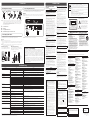
Attaching Euroblock Plugs
1 2 3 4
Loosen
Tighten
Slotted
screwdriver
Approx. 5 mm
(approx. 0.2”)
Terminal
screw
Euroblock plug
NOTE • You must use the supplied Euroblock plugs. If the plugs have been lost, please contact your Yamaha dealer.
• To prepare the cable for attachment to a Euroblock connector, strip the wire as shown in the illustration using
stranded wire to make connections. With a Euroblock connection, stranded wires may be prone to breakage
because of metal fatigue due to the weight of the cable or due to vibration. When rack mounting your device,
use a lacing bar when possible to bundle and fasten the cables.
• Do not tin (solder) the exposed end.
1
Loosen terminal screws.
2
Insert cables.
3
Securely tighten terminal screws.
4
Insert the Euroblock plug into a terminal of this device.
Connecting Speaker Cables
The [SPEAKERS] output connectors on the rear panel are barrier strip type connectors. The connections
are described below for two methods: using a spade lug and using a bare conductor.
Caution
• Ensure that load is not applied to the speaker cable.
• This device uses a BTL (Balanced Transformer-Less) connection method for the amplifier output. As the amplifier output
is sent to the positive and negative connectors, any contact with other terminals or the device chassis may lead to
malfunction.
NOTE Connect the cables so that the amplifier’s “+” and “-” symbols match those of the speaker. If they are reversed, the
phase will be reversed and the sound will not be output correctly.
When using a spade lug
Loosen the screw, insert the spade lug all
the way from below, and tighten the screw.
≤5.8mm
(≤0.23”)
≥3.2mm
(≥ 0.13”)
When using a bare conductor
Loosen the screw, wrap the conductor wire around the
barrier strip terminal, and tighten the screw. Be sure that
the bare wire does not touch the chassis.
* Actual size
15mm
*
(0.6”)
Speaker cable
Wire
should not
touch the
chassis.
Connecting External Devices
Connect a BGM (background music) tuner, a CD player, a portable audio player, etc. to the stereo input
jacks of this device. After finishing all connections, connect the power cord to an AC outlet.
Warning
When connecting the power cord to an AC outlet, an input signal will turn on the power of this device by the auto-wake
function. To avoid unexpected loud sounds, be sure to connect microphones and external devices with the power off
status.
MA2120 rear panel
RCA Euroblock
NOTE Refer to “Attaching Euroblock Plugs” for Euroblock plug installation.
Connections
Precautions for Rack Mounting
This unit is rated for operation at ambient temperatures ranging from 0 to 40 degrees Celsius. When
mounting the unit with other MA2120 unit(s) or other device(s) in an EIA standard equipment rack,
inter
nal temperatures can exceed the specified upper limit, resulting in impaired performance or
failure. When rack mounting the unit, always observe the following requirements to avoid heat buildup:
•
•
When mounting the unit in a rack with devices such as power amplifiers that generate a significant
amount of heat, leave more than 1U of space between the MA2120 and other equipment. Also either
leave the open spaces uncovered or install appropriate ventilating panels to minimize the possibility
of heat buildup.
To ensure sufficient airflow, leave the rear of the rack open and position it at least 10 centimeters
fr
om walls or other surfaces. If the rear of the rack can’t be left open, install a commercially available
fan or similar ventilating option to secure sufficient airflow. If you’ve installed a fan kit, there may be
cases in which closing the rear of the rack will produce a greater cooling effect. Refer to the rack
and/or fan unit manual for details.
Manual Development Department
© 2016 Yamaha Corporation
Published 02/2016 KSHD-A0
Printed in China
For details of products, please contact your nearest Yamaha representative or the authorized distributor listed below.
HEAD OFFICE
Yamaha Corporation, Audio Products Sales and Marketing Division
10-1, Nakazawa-cho, Naka-ku, Hamamatsu, Japan 430-8650
CANADA
Yamaha Canada Music Ltd.
135 Milner Avenue, Toronto, Ontario,
M1S 3R1, Canada
Tel: +1-416-298-1311
U.S.A.
Yamaha Corporation of America
6600 Orangethorpe Avenue, Buena Park, CA 90620,
U.S.A.
Tel: +1-714-522-9011
MEXICO
Yamaha de México, S.A. de C.V.
Av. Insurgentes Sur 1647 Piso 9, Col. San José
Insurgentes, Delegación Benito Juárez, México,
D.F., C.P. 03900
Tel: +52-55-5804-0600
BRAZIL
Yamaha Musical do Brasil Ltda.
Rua Fidêncio Ramos, 302 – Cj 52 e 54 – Torre B – Vila
Olímpia – CEP 04551-010 – São Paulo/SP, Brazil
Tel: +55-11-3704-1377
ARGENTINA
Yamaha Music Latin America, S.A.,
Sucursal Argentina
Olga Cossettini 1553, Piso 4 Norte,
Madero Este-C1107CEK,
Buenos Aires, Argentina
Tel: +54-11-4119-7000
VENEZUELA
Yamaha Musical de Venezuela, C.A.
AV. Manzanares, C.C. Manzanares Plaza,
Piso 4, Oficina 0401, Baruta, Caracas, Venezuela
Tel: +58-212-943-1877
PANAMA AND OTHER LATIN
AMERICAN COUNTRIES/
CARIBBEAN COUNTRIES
Yamaha Music Latin America, S.A.
Edif. Torre Banco General, Piso 7, Urbanización
Marbella, Calle 47 y Aquilino de la Guardia,
Ciudad de Panamá, República de Panamá
Tel: +507-269-5311
THE UNITED KINGDOM/IRELAND
Yamaha Music Europe GmbH (UK)
Sherbourne Drive, Tilbrook, Milton Keynes,
MK7 8BL, U.K.
Tel: +44-1908-366700
GERMANY
Yamaha Music Europe GmbH
Siemensstrasse 22-34, 25462 Rellingen, Germany
Tel: +49-4101-303-0
SWITZERLAND/LIECHTENSTEIN
Yamaha Music Europe GmbH, Rellingen,
Branch Switzerland in Zürich
Seefeldstrasse 94, 8008 Zürich, Switzerland
Tel: +41-44-3878080
AUSTRIA/BULGARIA
Yamaha Music Europe GmbH Branch Austria
Schleiergasse 20, 1100 Wien, Austria
Tel: +43-1-60203900
CZECH REPUBLIC/HUNGARY/
ROMANIA/SLOVAKIA/SLOVENIA
Yamaha Music Europe GmbH
Branch Austria
Schleiergasse 20, 1100 Wien, Austria
Tel: +43-1-60203900
POLAND/LITHUANIA/LATVIA/ESTONIA
Yamaha Music Europe GmbH
Sp.z o.o. Oddzial w Polsce
ul. Wrotkowa 14, 02-553 Warsaw, Poland
Te
l: +48-22-880-08-88
MALTA
Olimpus Music Ltd.
Valletta Road, Mosta MST9010, Malta
Tel: +356-2133-2093
NETHERLANDS/BELGIUM/
LUXEMBOURG
Yamaha Music Europe Branch Benelux
Clarissenhof 5b, 4133 AB Vianen, The Netherlands
Tel: +31-347-358040
FRANCE
Yamaha Music Europe
7 rue Ambroise Croizat, Zone d'activités de Pariest,
77183 Croissy-Beaubourg, France
Tel: +33-1-6461-4000
ITALY
Yamaha Music Europe GmbH, Branch Italy
Viale Italia 88, 20020, Lainate (Milano), Italy
Tel: +39-02-93577-1
SPAIN/PORTUGAL
Yamaha Music Europe GmbH Ibérica, Sucursal
en España
Ctra. de la Coruna km. 17,200, 28231
Las Rozas de Madrid, Spain
Tel: +34-91-639-88-88
GREECE
Philippos Nakas S.A. The Music House
19th klm. Leof. Lavriou 190 02 Peania – Attiki,
Greece
Tel: +30-210-6686168
SWEDEN/FINLAND/ICELAND
Yamaha Music Europe GmbH Germany filial
Scandinavia
JA Wettergrensgata 1, 400 43 Göteborg, Sweden
Tel: +46-31-89-34-00
DENMARK
Yamaha Music Denmark,
Fillial of Yamaha Music Europe GmbH, Tyskland
Generatorvej 8C, ST. TH. , 2860 Søborg, Denmark
Tel: +45-44-92-49-00
NORWAY
Yamaha Music Europe GmbH Germany -
Norwegian Branch
Grini Næringspark 1, 1361 Østerås, Norway
Tel: +47-6716-7800
RUSSIA
Yamaha Music (Russia) LLC.
Room 37, entrance 7, bld. 7, Kievskaya street,
Moscow, 121059, Russia
Tel: +7-495-626-5005
OTHER EUROPEAN COUNTRIES
Yamaha Music Europe GmbH
Siemensstrasse 22-34, 25462 Rellingen, Germany
Te
l: +49-4101-3030
Yamaha Music Gulf FZE
JAFZA-16, Office 512, P.O.Box 17328,
Jebel Ali FZE, Dubai, UAE
Tel: +971-4-801-1500
TURKEY
Yamaha Music Europe GmbH
Merkezi Almanya Türkiye İstanbul Şubesi
Maslak Meydan Sodak, Spring Giz Plaza Bagimsiz
Böl. No:3, Sanyer Istanbul, Turkey
Tel: +90-212-999-8010
CYPRUS
Yamaha Music Europe GmbH
Siemensstrasse 22-34, 25462 Rellingen, Germany
Tel: +49-4101-303-0
OTHER COUNTRIES
Yamaha Music Gulf FZE
JAFZA-16, Office 512, P.O.Box 17328,
Je
bel Ali FZE, Dubai, UAE
Tel: +971-4-801-1500
THE PEOPLE’S REPUBLIC OF CHINA
Yamaha Music & Electronics (China) Co.,Ltd.
2F, Yunhedasha, 1818 Xinzha-lu, Jingan-qu,
Shanghai, China
Tel: +86-400-051-7700
INDIA
Yamaha Music India Private Limited
Spazedge Building, Ground Floor, Tower A,
Sector-47, Gurgaon- Sohna Road, Gurgaon-122002,
Haryana, India
Tel: +91-124-485-3300
INDONESIA
PT. Yamaha Musik Indonesia (Distributor)
Yamaha Music Center Bldg. Jalan Jend. Gatot
Subroto Kav. 4, Jakarta 12930, Indonesia
Tel: +62-21-520-2577
KOREA
Yamaha Music Korea Ltd.
8F, Dongsung Bldg. 21, Teheran-ro 87-gil,
Gangnam-gu, Seoul, 135-880, Korea
Tel: +82-2-3467-3300
MALAYSIA
Yamaha Music (Malaysia) Sdn. Bhd.
No.8, Jalan Perbandaran, Kelana Jaya, 47301
Petaling Jaya, Selangor, Malaysia
Tel: +60-3-78030900
SINGAPORE
Yamaha Music (Asia) Private Limited
Block 202 Hougang Street 21, #02-00,
Singapore 530202, Singapore
Te
l: +65-6740-9200
TAIWAN
Yamaha Music & Electronics Taiwan Co.,Ltd.
2F., No.1, Yuandong Rd. Banqiao Dist.
New Taipei City 22063, Taiwan
Tel: +886-2-7741-8888
THAILAND
Siam Music Yamaha Co., Ltd.
3, 4, 15, 16th Fl., Siam Motors Building,
891/1 Rama 1 Road, Wangmai,
Pathumwan, Bangkok 10330, Thailand
Tel: +66-2215-2622
VIETNAM
Yamaha Music Vietnam Company Limited
15th Floor, Nam A Bank Tower, 201-203 Cach
Mang Thang Tam St., Ward 4, Dist.3,
Ho Chi Minh City, Vietnam
Tel: +84-8-3818-1122
OTHER ASIAN COUNTRIES
Yamaha Corporation
Sales & Marketing Division
10-1, Nakazawa-cho, Naka-ku, Hamamatsu,
Japan 430-8650
Tel: +81-53-460-2312
AUSTRALIA
Yamaha Music Australia Pty. Ltd.
Level 1, 99 Queensbridge Street, Southbank,
Vic. 3006, Australia
Tel: +61-3-9693-5111
COUNTRIES AND TRUST
TERRITORIES IN PACIFIC OCEAN
Yamaha Corporation
Sales & Marketing Division
10-1, Nakazawa-cho, Naka-ku, Hamamatsu,
Japan 430-8650
Tel: +81-53-460-2312
NORTH AMERICA
CENTRAL & SOUTH AMERICA
EUROPE
AFRICA
MIDDLE EAST
ASIA
OCEANIA
PA41
PLEASE READ CAREFULLY BEFORE
PROCEEDING
Please keep this manual in a safe place for future reference.
WARNING
Always follow the basic precautions listed below to avoid
the possibility of serious injury or even death from electrical
shock, short-circuiting, damages, re or other hazards. These
precautions include, but are not limited to, the following:
Power supply/power cord
• Do not place the power cord near heat sources such as
heaters or radiators, and do not excessively bend or otherwise
damage the cord, place heavy objects on it, or place it in a
position where anyone could walk on, trip over, or roll anything
over it.
• Only use the voltage specified as correct for the device. The
required voltage is printed on the name plate of the device.
• Use only the supplied power cord/plug.
If you intend to use the device in an area other than in the
one you purchased, the included power cord may not be
compatible. Please check with your Yamaha dealer.
• Check the electric plug periodically and remove any dirt or
dust which may have accumulated on it.
• When setting up the device, make sure that the AC outlet you
are using is easily accessible. If some trouble or malfunction
occurs, immediately turn off the power switch and disconnect
the plug from the outlet. Even when the power switch is turned
off, as long as the power cord is not unplugged from the wall
AC outlet, the device will not be disconnected from the power
source. When installing in a rack, connect a power cut-off
device additionally to power off the device handily.
• Remove the electric plug from the outlet when the device is not
to be used for extended periods of time, or during electrical
storms.
• Be sure to connect to an appropriate outlet with a protective
grounding connection. Improper grounding can result in
electrical shock, damage to the device(s), or even fire.
Do not open
• This device contains no user-serviceable parts. Do not
open the device or attempt to disassemble the internal
parts or modify them in any way. If it should appear to be
malfunctioning, discontinue use immediately and have it
inspected by qualified Yamaha service personnel.
Water warning
• Do not expose the device to rain, use it near water or in damp
or wet conditions, or place on it any containers (such as vases,
bottles or glasses) containing liquids which might spill into any
openings. If any liquid such as water seeps into the device,
turn off the power immediately and unplug the power cord from
the AC outlet. Then have the device inspected by qualified
Yamaha service personnel.
• Never insert or remove an electric plug with wet hands.
Hearing loss
• Avoid setting all equalizer controls and volume controls to
their maximum. Depending on the condition of the connected
devices, doing so may result in feedback that can cause
hearing loss and damage the speakers.
• Do not use speakers for a long period of time at a high or
uncomfortable volume level, since this can cause permanent
hearing loss. If you experience any hearing loss or ringing in
the ears, consult a physician.
• When turning on the AC power in your audio system, always
turn on the device LAST, to avoid hearing loss and speaker
damage. When turning the power off, the device should be
turned off FIRST for the same reason.
Fire warning
• Do not place any burning items or open flames near the
device, since they may cause a fire.
If you notice any abnormality
• If any of the following problems occur, immediately turn off the
power switch and disconnect the electric plug from the outlet.
– The power cord or plug becomes frayed or damaged.
– Unusual smells or smoke are emitted.
– Some object has been dropped into the device.
– There is a sudden loss of sound during use of the device.
– Cracks or other visible damage appear on the device.
Then have the device inspected or repaired by qualified
Yamaha service personnel.
• If this device should be dropped or damaged, immediately
turn off the power switch, disconnect the electric plug from
the outlet, and have the device inspected by qualified Yamaha
service personnel.
CAUTION
Always follow the basic precautions listed below to avoid the
possibility of physical injury to you or others, or damage to
the device or other property. These precautions include, but
are not limited to, the following:
Power supply/power cord
• When removing the electric plug from the device or an outlet,
always hold the plug itself and not the cord. Pulling by the cord
can damage it.
Location
• Do not place the device in an unstable position where it might
accidentally fall over and cause injuries.
• Do not block the vents. This device has ventilation holes at the
top/sides to prevent the internal temperature from becoming
too high. In particular, do not place the device on its side or
upside down. Inadequate ventilation can result in overheating,
possibly causing damage to the device(s), or even fire.
• When attempting to dissipate heat on the device, when
installing it:
– Do not cover it with any cloth.
– Do not install it on a carpet or rug.
– Make sure the top surface faces up; do not install on its
sides or upside down.
– Do not use the device in a confined, poorly-ventilated
location.
Inadequate ventilation can result in overheating, possibly
causing damage to the device(s), or even fire. Make sure that
there is adequate space around the device: at least 10cm
above, 10cm at the sides and 10cm behind.
• Do not place the device in a location where it may come into
contact with corrosive gases or salt air. Doing so may result in
malfunction.
• Before moving the device, remove all connected cables.
• If the device is mounted in an EIA standard rack, carefully
read the section “Precautions for Rack Mounting” on page
1. Inadequate ventilation can result in overheating, possibly
causing damage to the device(s), malfunction, or even fire.
Connections
• Before connecting the device to other devices, turn off the
power for all devices. Also, before turning the power of all
devices on or off, make sure that all volume levels are set to
the minimum. Failing to do so may result in electric shock,
hearing loss, or equipment damage.
• Use only speaker cables for connecting speakers to the
speaker jacks. Use of other types of cables may result in fire.
Maintenance
• Remove the power plug from the AC outlet when cleaning the
device.
Handling caution
• Do not touch or carry this device until it returns to normal
temperature, if the device has become excessively hot during
use or after using immediately. Prolonged contact may cause
low-temperature burns.
• Do not insert your fingers or hands in any gaps or openings on
the device (vents, panel, etc.).
• Avoid inserting or dropping foreign objects (paper, plastic,
metal, etc.) into any gaps or openings on the device (vents,
panel, etc.) If this happens, immediately turn off the power
unplug the power cord from the AC outlet, and have the device
inspected by qualified Yamaha service personnel.
• Do not rest your weight on the device or place heavy objects
on it, and avoid use excessive force on the buttons, switches
or connectors to prevent injuries.
Yamaha cannot be held responsible for damage caused by
improper use or modifications to the device.
NOTICE
To avoid the possibility of malfunction/ damage to the product,
damage to data, or damage to other property, follow the notices
below.
Handling and maintenance
• Do not use the device in the vicinity of a TV, radio, AV
equipment, mobile phone, or other electric devices. Otherwise,
the device, TV, or radio may generate noise.
• Do not expose the device to excessive dust or vibration, or
extreme cold or heat (such as in direct sunlight, near a heater,
or in a car during the day), in order to prevent the possibility
of panel disfiguration, unstable operation, or damage to the
internal components.
• Do not place vinyl, plastic or rubber objects on the device,
since this might discolor the panel.
• When cleaning the device, use a dry and soft cloth. Do not
use paint thinners, solvents, cleaning fluids, or chemical-
impregnated wiping cloths.
• Condensation can occur in the device due to rapid, drastic
changes in ambient temperature—when the device is moved
from one location to another, or air conditioning is turned
on or off, for example. Using the device while condensation
is present can cause damage. If there is reason to believe
that condensation might have occurred, leave the device
for several hours without turning on the power until the
condensation has completely dried out.
• Do not use this device for any purpose other than driving
loudspeakers.
• Always turn the power off when the device is not in use.
• Even when the [(z)] (Standby/On) switch is in standby status
(power lamp is off/ display is off), electricity is still flowing to
the instrument at the minimum level. When you are not using
the instrument for a long time, make sure you unplug the power
cord from the wall AC outlet.
Information
About this manual
• The illustrations as shown in this manual are for instructional
purposes only.
• The company names and product names in this manual are
the trademarks or registered trademarks of their respective
companies.
FCC INFORMATION (U.S.A.)
1. IMPORTANT NOTICE: DO NOT MODIFY THIS UNIT!
This product, when installed as indicated in the instructions
contained in this manual, meets FCC requirements.
Modifications not expressly approved by Yamaha may void
your authority, granted by the FCC, to use the product.
2. IMPORTANT:
When connecting this product to accessories and/or
another product use only high quality shielded cables.
Cable/s supplied with this product MUST be used. Follow all
installation instructions. Failure to follow instructions could
void your FCC authorization to use this product in the USA.
3. NOTE:
This product has been tested and found to comply with the
requirements listed in FCC Regulations, Part 15 for Class
“B” digital devices. Compliance with these requirements
provides a reasonable level of assurance that your use
of this product in a residential environment will not result
in harmful interference with other electronic devices. This
equipment generates/uses radio frequencies and, if not
installed and used according to the instructions found in
the users manual, may cause interference harmful to the
operation of other electronic devices. Compliance with FCC
regulations does not guarantee that interference will not occur
in all installations. If this product is found to be the source of
interference, which can be determined by turning the unit
“OFF” and “ON”, please try to eliminate the problem by using
one of the following measures:
Relocate either this product or the device that is being
affected by the interference.
Utilize power outlets that are on different branch (circuit
breaker or fuse) circuits or install AC line filter/s.
In the case of radio or TV interference, relocate/reorient
the antenna. If the antenna lead-in is 300 ohm ribbon lead,
change the lead-in to co-axial type cable.
If these corrective measures do not produce satisfactory
results, please contact the local retailer authorized to
distribute this type of product. If you can not locate the
appropriate retailer, please contact Yamaha Corporation of
America, Electronic Service Division, 6600 Orangethorpe
Ave, Buena Park, CA90620
The above statements apply ONLY to those products
distributed by Yamaha Corporation of America or its
subsidiaries.
(class B)
OBSERVERA!
Apparaten kopplas inte ur växelströmskällan (nätet) så
länge som den ar ansluten till vägguttaget, även om själva
apparaten har stängts av.
ADVARSEL: Netspændingen til dette apparat er IKKE
afbrudt, sålænge netledningen sidder i en stikkontakt, som er
tændt — også selvom der er slukket på apparatets afbryder.
VAROITUS: Laitteen toisiopiiriin kytketty käyttökytkin ei irroita
koko laitetta verkosta.
(standby)
IMPORTANT NOTICE FOR THE UNITED KINGDOM
Connecting the Plug and Cord
WARNING: THIS APPARATUS MUST BE EARTHED
IMPORTANT. The wires in this mains lead are coloured in
accordance with the following code:
GREEN-AND-YELLOW : EARTH
BLUE : NEUTRAL
BROWN : LIVE
As the colours of the wires in the mains lead of this apparatus
may not correspond with the coloured markings identifying
the terminals in your plug proceed as follows:
The wire which is coloured GREEN-and-YELLOW must be
connected to the terminal in the plug which is marked by the
letter E or by the safety earth symbol
or colored GREEN or
GREEN-and-YELLOW.
The wire which is coloured BLUE must be connected to
the terminal which is marked with the letter N or coloured
BLACK.
The wire which is coloured BROWN must be connected to
the terminal which is marked with the letter L or coloured
RED.
(3 wires)
In Finland: Laite on liitettävä suojamaadoituskoskettimilla
varustettuun pistorasiaan.
In Norway: Apparatet må tilkoples jordet stikkontakt.
In Sweden: Apparaten skall anslutas till jordat uttag.
(class I hokuo)
이 기기는 가정용(B급) 전자파적합기기로서 주로 가정에서
사용하는 것을 목적으로 하며, 모든 지역에서 사용할 수
있습니다.
(class b korea)
CAU TI ON
RISK OF ELECTRIC SHOCK
DO NOT OPEN
CAUTION:
TO REDUCE THE RISK OF ELECTRIC SHOCK,
DO NOT REMOVE COVER (OR BACK).
NO USER-SERVICEABLE PARTS INSIDE.
REFER SERVICING TO QUALIFIED SERVICE PERSONNEL.
The above warning is located
on the top of the unit.
Explanation of Graphical Symbols
The lightning flash with arrowhead symbol
within an equilateral triangle is intended to
alert the user to the presence of uninsulated
“dangerous voltage” within the product’s
enclosure that may be of sufficient magnitude
to constitute a risk of electric shock to persons.
The exclamation point within an equilateral
triangle is intended to alert the user to
the presence of important operating and
maintenance (servicing) instructions in the
literature accompanying the product.
IMPORTANT SAFETY INSTRUCTIONS
1 Read these instructions.
2 Keep these instructions.
3 Heed all warnings.
4 Follow all instructions.
5 Do not use this apparatus near water.
6 Clean only with dry cloth.
7 Do not block any ventilation openings. Install in
accordance with the manufacturer’s instructions.
8 Do not install near any heat sources such as radiators,
heat registers, stoves, or other apparatus (including
ampliers) that produce heat.
9 Do not defeat the safety purpose of the polarized or
grounding-type plug. A polarized plug has two blades
with one wider than the other. A grounding type plug
has two blades and a third grounding prong. The wide
blade or the third prong are provided for your safety. If
the provided plug does not t into your outlet, consult
an electrician for replacement of the obsolete outlet.
10 Protect the power cord from being walked on or
pinched particularly at plugs, convenience receptacles,
and the point where they exit from the apparatus.
11 Only use attachments/accessories specied by the
manufacturer.
12 Use only with the cart, stand, tripod,
bracket, or table specied by the
manufacturer, or sold with the
apparatus. When a cart is used, use
caution when moving the cart/
apparatus combination to avoid injury
from tip-over.
13 Unplug this apparatus during lightning
storms or when unused for long periods of time.
14 Refer all servicing to qualied service personnel.
Servicing is required when the apparatus has been
damaged in any way, such as power-supply cord or
plug is damaged, liquid has been spilled or objects
have fallen into the apparatus, the apparatus has been
exposed to rain or moisture, does not operate normally,
or has been dropped.
WARNING
TO REDUCE THE RISK OF FIRE OR ELECTRIC SHOCK, DO NOT EXPOSE THIS APPARATUS TO RAIN OR MOISTURE.
(UL60065_03)
Information for Users on Collection and Disposal of Old Equipment
This symbol on the products, packaging, and/or accompanying documents means that used electrical and
electronic products should not be mixed with general household waste.
For proper treatment, recovery and recycling of old products, please take them to applicable collection
points, in accordance with your national legislation and the Directives 2002/96/EC.
By disposing of these products correctly, you will help to save valuable resources and prevent any potential
negative effects on human health and the environment which could otherwise arise from inappropriate waste
handling.
For more information about collection and recycling of old products, please contact your local municipality,
your waste disposal service or the point of sale where you purchased the items.
[For business users in the European Union]
If you wish to discard electrical and electronic equipment, please contact your dealer or supplier for further
information.
[Information on Disposal in other Countries outside the European Union]
This symbol is only valid in the European Union. If you wish to discard these items, please contact your local
authorities or dealer and ask for the correct method of disposal.
(weee_eu_en_01)
PRECAUTIONS
Troubleshooting
Symptom Cause Solution
The power does not turn on. The power cord is disconnected. Connect the power cord.
The protection function of the device is activated. Pull out the power cord to turn off the power, and make sure the connection is secure. Wait several minutes, and then turn
on the power again. Be sure to install the device in a location not subject to high temperatures, such as a shaded, well-
ventilated place.
The [S] and [G] pins of [REMOTE] connector are shorted. Use the controller connected to the [REMOTE] connector to turn on the power.
The power turns off. The auto-power-off function has activated. When there is no input signal for 25 minutes, the system automatically switches to standby mode. This function cannot be
disabled.
The power automatically turns on. The auto-wake function has activated. The auto-wake function is turned on by default. If you wish to turn it off, set [SETUP] DIP switches 3 and 4 to their downward
positions while the system is in standby mode. Then, turn the power on by the [z] button.
No sound is heard. The volume is lowered too much with the [VOLUME A] or [VOLUME B] knobs. Turn the applicable knob to the right.
No audio signal is being input. Check the output signal from an external device that has been connected.
The input level has been lowered too much with the [INPUT] level knob. Turn the [INPUT] level knob for the corresponding input channel to the right.
Zone selection is not appropriate. Check the input channel [ROUTE] switch setting.
Phantom power is turned off, even when using a condenser microphone. Set the [GAIN] switch for the condenser microphone channel to “MIC(+24V).”
Zone B is being used while the amplifier output is set to 200W. When the amplifier output is set to 200W, there is no signal output from zone B.
The settings via a control panel are retained. To initialize the settings, refer to “Initializing the settings via connected control panels (DCP Setup)” in the Setup Guide.
The volume is low. The device is set to low-impedance connection; however, speakers with high-
impedance input have been connected.
Match the impedance settings of this device and the connected speakers.
The device is set to line level, even though a microphone has been connected. Set the [GAIN] switch for the input channel to “MIC.”
The sound is distorted. The input level from microphones or external devices is too high. Turn the [INPUT] level knob to the left and adjust the volume. Adjust the output level of the external device.
The EQ level is too high. For the input EQ, press and hold the [SETUP] knob for at least one second. Then, select input level 3 (BASS) or input level 4
(TREBLE). Select the desired input channel and appropriately adjust. For the output EQ, use a tool such as a screwdriver to
adjust the [BASS] and [TREBLE] controls on the front panel.
The setting does not change even when
turning a knob.
The panel is locked.
To turn off the panel lock, switch all [SETUP] DIP switches 1 and 2 to the upward position, then use the [z] button to reset
the device.
The setting does not change even when
turning the [SETUP] knob.
The [SETUP] knob is locked.
The setting does not change even when
turning knobs other than the [VOLUME] knob.
Knobs other than the [VOLUME] knob are locked.
The stereo source connected to INPUT7 or
INPUT8 is not providing a valid stereo signal.
The [MODE] switch is set to MONO. Set the [MODE] switch to STEREO.
The stereo source connected to INPUT7 or
INPUT8 is not being played correctly in each
zone.
The [MODE] switch is set to STEREO. Set the [MODE] switch to MONO, then set the [ROUTE] switch to an appropriate setting.
DIP switch settings are not applied to the
device.
The [z] button has not been used to turn the device on. Changes to DIP switch settings are only applied after the device has been turned on by the [z] button. They are not applied
if the power is turned on by the auto-power-on function, or by control via the [REMOTE] connector. Use the [z] button on the
front panel to turn the device on.
The sound drops out, and the [z] button and
[LIMIT] indicator flash three times.
The device is set to high-impedance connection; however, speakers with low-
impedance input have been connected or too many speakers are connected.
Match the impedance setting and the input rating setting of this device and the speakers.
When the device is set to low-impedance connection, the total impedance of
the connected speakers is less than the impedance setting of this device.
Match the impedance settings of this device and the connected speakers.
The speaker cable is shorted. Inspect the connection of the speaker cables.
The [z] button and [LIMIT] indicator continue
to flash. The sound goes off.
The internal temperature of the device is extremely high. Pull out the power cord, leave the device at a well-ventilated place, and turn the device back on several minutes later.
Heat dissipation slits are covered or the device is placed in a confined place
with poor ventilation.
The protection function of the device is activated. Check the installation location and surrounding environment. Be sure to
install the device in a location not subject to high temperatures, such as a shaded, well-ventilated place.
The device settings do not match speaker impedance. The protection function of the device is activated. Match the impedance settings of this device and the connected speakers.
Loud sound that exceeds the performance specifications of the device is
continually generated.
Lower the volume.
• Refer also to the Yamaha Pro Audio website that provides a FAQ (a list of frequently asked questions, with answers).
http://www.yamahaproaudio.com/
• If taking the above steps does not solve the problem, contact your Yamaha dealer for repair.
The model number, serial number, power requirements, etc.,
may be found on or near the name plate, which is at the top
of the unit. You should note this serial number in the space
provided below and retain this manual as a permanent record
of your purchase to aid identification in the event of theft.
Model No.
Serial No.
Yamaha Pro Audio global website
http://www.yamahaproaudio.com/
Yamaha Downloads
http://download.yamaha.com/
(rear_en_01)
-
 1
1
-
 2
2


Yamaha MA2030a Bedienungsanleitung
- Kategorie
- Zusätzliche Musikausrüstung
- Typ
- Bedienungsanleitung
- Dieses Handbuch eignet sich auch für
in anderen Sprachen
- English: Yamaha MA2030a Owner's manual
- français: Yamaha MA2030a Le manuel du propriétaire
- español: Yamaha MA2030a El manual del propietario
- italiano: Yamaha MA2030a Manuale del proprietario
- русский: Yamaha MA2030a Инструкция по применению
- Nederlands: Yamaha MA2030a de handleiding
- português: Yamaha MA2030a Manual do proprietário
- dansk: Yamaha MA2030a Brugervejledning
- polski: Yamaha MA2030a Instrukcja obsługi
- čeština: Yamaha MA2030a Návod k obsluze
- svenska: Yamaha MA2030a Bruksanvisning
- Türkçe: Yamaha MA2030a El kitabı
- suomi: Yamaha MA2030a Omistajan opas
- română: Yamaha MA2030a Manualul proprietarului
Verwandte Artikel
-
Yamaha MA2030a Bedienungsanleitung
-
-
-
Yamaha MA2030 Bedienungsanleitung
-
-
-
-
Yamaha MTX3 Bedienungsanleitung
-
-