Yamaha YST-SW45 Bedienungsanleitung
- Kategorie
- Subwoofer
- Typ
- Bedienungsanleitung

Active Servo Processing Subwoofer System
Caisson de grave avec asservissement actif
YST-SW45
B G R T
OWNER’S MANUAL
MODE D’EMPLOI
BEDIENUNGSANLEITUNG
BRUKSANVISNING
MANUALE DI ISTRUZIONI
MANUAL DE INSTRUCCIONES
GEBRUIKSAANWIJZING

2
Thank you for selecting this YAMAHA subwoofer system.
CAUTION: READ THIS BEFORE OPERATING YOUR UNIT.
1. To assure the finest performance, please read this manual
carefully. Keep it in a safe place for future reference.
2. Install this unit in a cool, dry, clean place, away from
windows, heat sources, sources of excessive vibration,
dust, moisture and cold. Avoid sources of humming
(transformers, motors). To prevent fire or electrical shock,
do not expose the unit to rain or water.
3. Never open the cabinet. If something drops into the set,
contact your dealer.
4. Do not use force on switches, controls or connection wires.
When moving the unit, first disconnect the power plug and
the wires connected to other equipment. Never pull the
wire itself.
5. Do not attempt to clean the unit with chemical solvents;
this might damage the finish. Use a clean, dry cloth.
6. Be sure to read the “TROUBLESHOOTING” section
regarding common operating errors before concluding that
the unit is faulty.
7. When not planning to use this unit for long periods of time
(i.e., vacation, etc.), disconnect the AC power plug from
the wall outlet.
8. To prevent lightning damage, disconnect the AC power
plug when there is an electrical storm.
9. Since this unit has a built-in power amplifier, heat will
radiate from the rear panel. Therefore, place the unit apart
from the walls, allowing enough space above, behind and
on the both sides of the unit to prevent fire and damage.
Also, do not position with the rear panel facing down on
the floor or other surface.
<For U.K. and Europe models only >
Be sure to allow a space of at least 20 cm above, behind
and on the both sides of the unit.
10.Super-bass frequencies reproduced by this unit may cause
a turntable to generate a howling sound. In such a case,
move this unit away from the turntable.
11. Vibration generated by super-bass frequencies may cause
images on a TV to be distorted. In such a case, move this
unit away from the TV set.
12.This unit features a magnetically shielded design, but there
is still a chance that placing it too close to a TV set might
impair picture color. Should this happen, move this unit
away from the TV set.
13.If you hear distortion (i.e., unnatural, intermittent “rapping”
or “hammering” sounds) coming from this unit, reduce the
volume level. Extremely loud playing of a movie
soundtrack’s low frequency, bass-heavy sounds or
similarly loud popular music passages can damage this
speaker system.
14. Voltage Selector (General and China Models only)
The voltage selector on the rear panel of this unit must
be set for your local main voltage BEFORE plugging
into the AC main supply.
Voltages are AC 110/120/220/240V, 50/60 Hz.
IMPORTANT
Please record the serial number of this unit in the space
below.
Serial No.:
The serial number is located on the rear of the unit.
Retain this Owner’s Manual in a safe place for future
reference.
15.Secure placement or installation is the owner’s
responsibility.
YAMAHA shall not be liable for any accident caused
by improper placement or installation of speakers.
For U.K. customers
If the socket outlets in the home are not suitable for the plug
supplied with this appliance, it should be cut off and an
appropriate 3 pin plug fitted. For details, refer to the
instructions described below.
Note: The plug severed from the mains lead must be
destroyed, as a plug with bared flexible cord is hazardous if
engaged in a live socket outlet.
SPECIAL INSTRUCTIONS FOR U.K. MODEL
IMPORTANT
THE WIRES IN THE MAINS LEAD ARE COLOURED IN
ACCORDANCE WITH THE FOLLOWING CODE:
Blue: NEUTRAL
Brown: LIVE
As the colours of the wires in the mains lead of this
apparatus may not correspond with the coloured markings
identifying the terminals in your plug, proceed as follows:
The wire which is coloured BLUE must be connected to the
terminal which is marked with the letter N or coloured
BLACK. The wire which is coloured BROWN must be
connected to the terminal which is marked with the letter L or
coloured RED. Making sure that neither core is connected to
the earth terminal of the three pin plug.
FOR CANADIAN CUSTOMERS
TO PREVENT ELECTRIC SHOCK, MATCH WIDE BLADE
OF PLUG TO WIDE SLOT AND FULLY INSERT.
THIS CLASS B DIGITAL APPARATUS COMPLIES WITH
CANADIAN ICES-003.
WARNING
TO REDUCE THE RISK OF FIRE OR ELECTRIC SHOCK,
DO NOT EXPOSE THIS UNIT TO RAIN OR MOISTURE.

3
English
FEATURES
• This subwoofer system employs Advanced YAMAHA Active
Servo Technology which YAMAHA has developed for
reproducing higher quality super-bass sound. (Refer to page
10 for details on Advanced YAMAHA Active Servo Technol-
ogy.) This super-bass sound adds a more realistic, theater-
in-the-home effect to your stereo system.
• This unit can be added easily to your existing audio system
by connecting to either the speaker terminals or the line
output (pin jack) terminals of the amplifier.
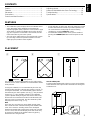
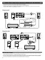
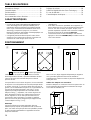
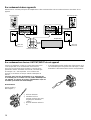
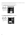
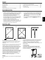
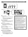
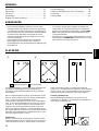
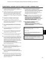
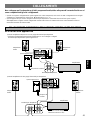
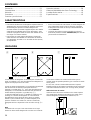
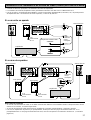
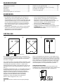
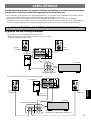
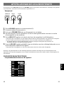
PLACEMENT
One subwoofer will have a good effect on your audio system,
however, the use of two subwoofers is recommended to obtain
more presence.
If using one subwoofer, it is recommended to place it on the
outside of either the right or the left main speaker. (See fig. Å.)
If using two subwoofers, it is recommended to place them on
the outside of each main speaker. (See fig. ı.) The placement
shown in fig. Ç is also possible, however, if the subwoofer
system is placed directly facing the wall, the bass effect may
die because the sound from it and the sound reflected by the
wall may cancel. To prevent this, face the subwoofer system
obliquely to the wall as in fig. Å or ı.
Note
There may be a case that you cannot obtain enough super-
bass sounds from this unit when listening at the middle of the
room. This is because “standing waves” have developed
between two parallel walls and the bass sounds are canceled.
In such a case, face the unit obliquely to the wall. It also may
be necessary to break up the parallel surfaces by placing
bookshelves etc. along the walls.
( : subwoofer, : main speaker)
CONTENTS
Adjusting volume........................................................8
Advanced YAMAHA Active Servo Technology..........10
Troubleshooting ........................................................11
Specifications ...........................................................11
Caution.......................................................................2
Features .....................................................................3
Placement ..................................................................3
Connections ...............................................................4
Controls and their functions .......................................7
Çı
• For the effective use of this unit, this unit’s super-bass sound
must be matched to the sounds of your main speakers. You
can create the best sound quality for various listening
conditions by using the HIGH CUT control.
• The Automatic Standby function saves you the trouble of
pressing the STANDBY/ON button to turn the power on and
off.
Å
Use the rubber pads
Put the provided rubber pads at the four corners on the bottom
of the subwoofer unit to prevent the subwoofer unit moving due
to vibrations etc.

4
AB
OUTPUT INPUT2
TO SPEAKERS
INPUT1
FROM AMPLIFIER
LOW
HIGH
OFF
AUTO
STANDBY
POWER
ON
OFF
OUTPUT INPUT2
TO SPEAKERS
INPUT1
FROM AMPLIFIER
LOW
HIGH
OFF
AUTO
STANDBY
OUTPUT INPUT2
TO SPEAKERS
INPUT1
FROM AMPLIFIER
LOW
HIGH
OFF
AUTO
STANDBY
POWER
ON
OFF
OUTPUT INPUT2
TO SPEAKERS
INPUT1
FROM AMPLIFIER
LOW
HIGH
OFF
AUTO
STANDBY
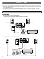
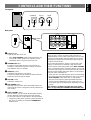
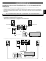
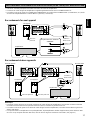
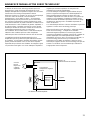
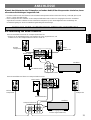
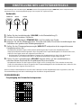
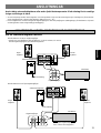
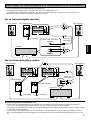
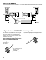
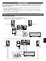
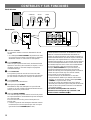
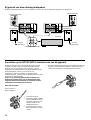
CONNECTIONS
Never plug in the subwoofer and other audio/video components until all connections are completed.
• When making connections between this unit and other components, be sure all connections are made firmly and correctly; L (left)
to L, R (right) to R, + to + and – to –.
• This unit can be connected to either the speaker terminals or the line output (pin jack) terminals of the amplifier. Choose one of
the connections shown below according to your audio system. Refer also to the owner’s manuals supplied for your audio system.
CONNECTING TO SPEAKER TERMINALS OF THE AMPLIFIER
Using one unit
Amplifier
Speaker terminals
To AC outlet
Right speaker
This unit
Left speaker
Amplifier
Speaker terminals
To AC outlet
Right speaker
This unit
Left speaker
(Both A and B speaker outputs
must be ON.)
When your amplifier has two sets of speaker terminals
When your amplifier has one set of speaker terminals
• Disconnect your main speakers from the amplifier if connected, and connect them
to the speaker terminals of this unit.

5
English
OUTPUT INPUT2
TO SPEAKERS
INPUT1
FROM AMPLIFIER
LOW
HIGH
OFF
AUTO
STANDBY
OUTPUT INPUT2
TO SPEAKERS
INPUT1
FROM AMPLIFIER
LOW
HIGH
OFF
AUTO
STANDBY
POWER
ON
OFF
OUTPUT INPUT2
TO SPEAKERS
INPUT1
FROM AMPLIFIER
LOW
HIGH
OFF
AUTO
STANDBY
POWER
ON
OFF
OUTPUT INPUT2
TO SPEAKERS
INPUT1
FROM AMPLIFIER
LOW
HIGH
OFF
AUTO
STANDBY
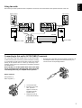
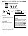
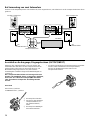
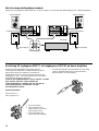
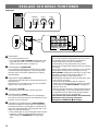
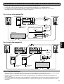
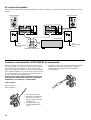
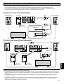
Connecting to this unit’s OUTPUT/INPUT terminals
For connections, keep the speaker wires as short as possible.
(Cut the excessive wire, if necessary.) If the connections are faulty,
no sound will be heard from the speakers. Make sure that the
polarity of the speaker wires is correct, by observing + and –
markings. If these wires are reversed, the sound will be unnatural
and will lack bass.
Do not let the core of the speaker wires touch each other
and do not let them touch the metal parts of this unit as this
could damage this unit, your amplifier and/or speakers.
How to Connect:
Red: positive (+)
Black: negative (–)
1 Unscrew the knob.
2 Insert the core of the
wire. [Remove
approx. 5 mm (1/4”)
insulation from the
speaker wires.]
3 Tighten the knob to
secure the wire firmly.
* Banana Plug connections are also possible (except for U.K.
and Europe models). Simply insert the Banana Plug con-
nector into the corresponding terminal.
Using two units
Speaker terminals
To AC outlet
Right speaker
This unit
Left speaker
This unit
To AC outlet
Amplifier
Disconnect your main speakers from the amplifier if connected, and connect them to the speaker terminals of this unit.

6
OUTPUT INPUT2
TO SPEAKERS
INPUT1
FROM AMPLIFIER
LOW
HIGH
OFF
AUTO
STANDBY
OUTPUT INPUT2
TO SPEAKERS
INPUT1
FROM AMPLIFIER
LOW
HIGH
OFF
AUTO
STANDBY
POWER
ON
OFF
OUTPUT INPUT2
TO SPEAKERS
INPUT1
FROM AMPLIFIER
LOW
HIGH
OFF
AUTO
STANDBY
POWER
ON
OFF
OUTPUT INPUT2
TO SPEAKERS
INPUT1
FROM AMPLIFIER
LOW
HIGH
OFF
AUTO
STANDBY
PRE OUT
SUBWOOFER
OUTPUT INPUT2
TO SPEAKERS
INPUT1
FROM AMPLIFIER
LOW
HIGH
OFF
AUTO
STANDBY
POWER
ON
OFF
OUTPUT INPUT2
TO SPEAKERS
INPUT1
FROM AMPLIFIER
LOW
HIGH
OFF
AUTO
STANDBY
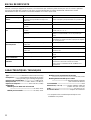
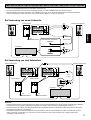
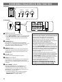
CONNECTING TO LINE OUTPUT (PIN JACK) TERMINALS OF THE AMPLIFIER
• Connect the main speakers to the speaker output terminals of the amplifier.
• Amplifier line output terminals are generally labeled PRE OUT or SUBWOOFER OUT.
• To connect with a YAMAHA DSP amplifier, connect the SUBWOOFER (or LOW PASS etc.) terminal on the rear of the DSP
amplifier to either the left (L) or right (R) INPUT 2 terminal.
Using one unit
Using two units
Amplifier
‹YAMAHA DSP amplifier›
To AC outlet
This unitLeft speaker
‹Amplifier›
This unit This unit
To AC outlet To AC outlet
Amplifier
Right speaker
Left speaker
Pin plug
cords
Pin plug
cords
Notes on the above connections
• When connected to line output terminals of the amplifier, other speakers should not be connected to the OUTPUT terminals on
the rear panel of the subwoofer. If connected, they will not produce sound.
• When connecting this unit to a monaural line output terminal of the amplifier, connect to either the left or right INPUT 2 terminal.
• For using a power amplifier and a preamplifier, the preamplifier must have two sets of PRE OUT terminals. If your preamplifier
has only one set of PRE OUT, connect this unit to the speaker terminals. (See page 4.)
Right speaker

7
English
POWER
ON
OFF
OUTPUT INPUT2
TO SPEAKERS
INPUT1
FROM AMPLIFIER
LOW
HIGH
OFF
AUTO
STANDBY
POWER
ON
OFF
OUTPUT INPUT2
TO SPEAKERS
INPUT1
FROM AMPLIFIER
LOW
HIGH
OFF
AUTO
STANDBY
STANDBY/ON HIGH CUT VOLUME
140 Hz
010
40 Hz
150 Hz
010
50 Hz
STANDBY/ON HIGH CUT VOLUME
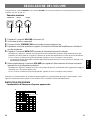
Front panel
Rear panel
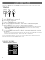
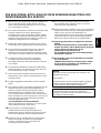
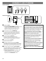
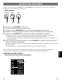
CONTROLS AND THEIR FUNCTIONS
Automatic Standby function
When you play a source, the power of this unit turns on
automatically by sensing audio signals input to this unit. This
unit turns into the standby mode automatically if the source
being played is stopped or the low frequency input signal is
cut off for several minutes.
This function will operate by sensing a certain level of low
frequency input signal. Its sensitivity is high in the HIGH
position and low in the LOW position of the AUTO STANDBY
switch. In the HIGH position, the power will turn on even with
a low level of input signal, but on the other hand this unit may
not turn into the standby mode when there is an input signal
even if its level is extremely low.
* There may be a case that the power turns on unexpectedly
by sensing noise from other appliances. If it occurs, set the
AUTO STANDBY switch to the OFF or LOW position.
* The level of low frequency input signal differs with each
source, and each different part on the same source. So,
this function may not operate properly depending on some
sources.
This function is available only when the power of this
unit is on (by setting the STANDBY/ON button Ÿ to ON).
~
Power indicator
Lights up while this unit is ON.
* If the AUTO STANDBY switch on the rear panel is set
to the LOW or HIGH position, this indicator is illumi-
nated dimly when no signal is input to this unit.
Ÿ
STANDBY/ON button
Each press of this button turns the unit on and off (on
standby). A small amount of power is always consumed
even while this unit is on standby.
!
HIGH CUT control
Adjusts the high frequency cut off point.
Frequencies higher than the frequency selected with this
control are all cut off (and not output).
⁄
VOLUME control
Adjusts the volume level.
@
Main POWER switch
Normally, leave this switch to the ON position. When you
will not use this unit for a long period, set this switch to the
OFF position.
¤
AUTO STANDBY switch
With this switch, you can activate the Automatic Standby
function. Normally, set the switch to the LOW position.
To cancel this function, set the switch to the OFF position.
* Change the setting of this switch only when the power of
this unit is on standby (by setting the STANDBY/ON
button to OFF).
¤
!
⁄
~
Ÿ
@

8
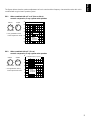
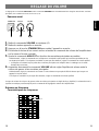
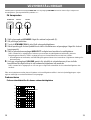
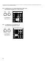
ADJUSTING VOLUME
Front panel
1 Set the VOLUME control to minimum (0).
2 Turn on the other components.
3 Press the STANDBY/ON button to turn on this unit.
4 Play any source and adjust the amplifier’s volume control to the desired listening level.
5 Adjust the HIGH CUT control according to the main speakers connected.
Normally, set the control to the main speaker’s rated minimum reproducible frequency*. If the desired response
cannot be obtained, adjust the control again to your preference.
* The main speaker’s rated minimum reproducible frequency can be looked up in the speakers’ catalog or
owner’s manual.
6 Turn up the VOLUME control gradually to adjust the volume balance between this unit and the
main speakers.
Normally, set the control to the level where you can obtain a little more bass effect than when this unit is not used.
If the desired response cannot be obtained, adjust the control again to your preference.
3 5 1,6
Once the volume balance between this unit and the main speakers is adjusted, you can adjust the volume of your
whole sound system by using only the amplifier’s volume control.
150 Hz
010
50 Hz
STANDBY/ON HIGH CUT VOLUME
20 50 100 200 500Hz
40
50
60
70
80
90
dB
HIGH CUT 100 Hz
HIGH CUT 150 Hz
HIGH CUT 50 Hz
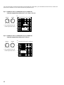
FREQUENCY RESPONSE
This unit’s frequency response
Adjustment of the HIGH CUT control and the VOLUME control needs to be changed according to the main speakers, listening
condition, source, etc.

9
English
20 50 100 200 500Hz
40
50
60
70
80
90
dB
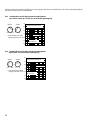
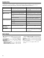
YST-SW45
Combined frequency response
20 50 100 200 500Hz
40
50
60
70
80
90
dB
YST-SW45
Combined frequency response
EX.1 When combined with a 3” or 4” (8cm or 10cm)
acoustic suspension, 2 way system main speakers
EX.2 When combined with a 5” (13 cm )
acoustic suspension, 2 way system main speakers
Main
speaker’s
response
HIGH CUT VOLUME
150 Hz
010
50 Hz
HIGH CUT VOLUME
150 Hz
010
50 Hz
* One graduation of this
control represents 10 Hz.
* One graduation of this
control represents 10 Hz.
Main
speaker’s
response
The figures below show the optimum adjustment of each control and the frequency characteristics when this unit is
combined with a typical main speaker system.

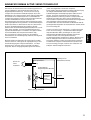
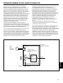
10
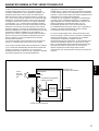
High-amplitude
bass sound
Cabinet
Port
Air woofer
(Helmholtz resonator)
Active
Servo
Processing
Amplifier
Signals
Signals of low amplitude
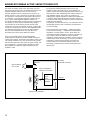
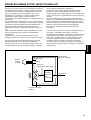
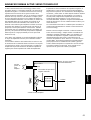
The theory of Yamaha Active Servo Technology has been
based upon two major factors, the Helmholtz resonator and
negative-impedance drive. Active Servo Processing
speakers reproduce the bass frequencies through an “air
woofer”, which is a port or opening in the speaker’s cabinet.
This opening is used instead of, and performs the functions
of, a woofer in a conventionally designed speaker system.
Thus, signals of low amplitude within the cabinet can,
according to the Helmholtz resonance theory, be output from
this opening as waves of great amplitude if the design is
such that the size of the opening and the volume of the
cabinet are in the correct proportion to satisfy a certain ratio.
In order to accomplish this, moreover, the amplitudes within
the cabinet must be both precise and of sufficient power
because these amplitudes must overcome the “load”
presented by the air that exists within the cabinet.
Thus it is this problem that is resolved through the
employment of a design in which the amplifier functions to
supply special signals. If the electrical resistance of the voice
coil could be reduced to zero, the movement of the speaker
unit would become linear with respect to signal voltage, and,
to accomplish this, a special negative-impedance output-
drive amplifier for subtracting output impedance of the
amplifier is used.
By employing negative-impedance drive circuits, the
amplifier is able to generate precise, low-amplitude low-
frequency waves with superior damping characteristics, and
these waves are then radiated from the cabinet opening as
high-amplitude signals. The system can, therefore, by
employing the negative-impedance output drive amplifier and
a speaker cabinet with the Helmholtz resonator, reproduce
an extremely wide range of frequencies with amazing sound
quality and less distortion.
The features described above, then, are combined to be the
fundamental structure of the conventional Yamaha Active
Servo Technology.
Our new Active Servo Technology — Advanced Yamaha
Active Servo Technology — adopted Advanced Negative
Impedance Converter (ANIC) circuits, which allows the
conventional negative impedance converter to dynamically
vary in order to select an optimum value for speaker
impedance variation. With this new ANIC circuits, Advanced
Yamaha Active Servo Technology can provide more stable
performance and improved maximum sound pressure
compared with the conventional Yamaha Active Servo
Technology, resulting in more natural and energetic bass
reproduction.
Advanced Negative-
impedance Converter
ADVANCED YAMAHA ACTIVE SERVO TECHNOLOGY

11
English
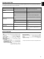
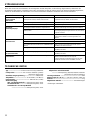
YST-SW45
Type ................ Active Servo Processing Subwoofer System
Speaker Unit .................... 20 cm (8”) cone woofer (JA2162)
magnetic shielding type x 1
Amplifier Output............................................. 70 W/5 ohms
High-Cut Filter ......................... 50 Hz–150 Hz (–24 dB/oct.)
Frequency Response.....................30 Hz–200 Hz (–10 dB)
Power Supply
U.S.A. and Canada models .................. AC 120 V, 60 Hz
Australia model..................................... AC 240 V, 50 Hz
U.K. and Europe models ...................... AC 230 V, 50 Hz
General and China models
................... AC 110/120/220/240 V, 50/60 Hz
..................(Adjustable with Voltage Selector)
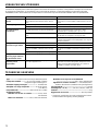
TROUBLESHOOTING
If the unit fails to operate normally, check the following points to determine whether the fault can be corrected by the simple meas-
ures suggested. If it cannot be corrected, or if the fault is not listed in the SYMPTOM column, disconnect the power cord and contact
your authorized YAMAHA dealer or service center for help.
SPECIFICATIONS
Power Consumption .......................................................55 W
Dimensions (W × H × D)........... 235 mm × 365 mm × 318 mm
(9-5/16” × 14-7/20” × 12-1/2”)
Weight .......................................................9 kg (19 lbs. 13 oz.)
Supplied Accessory.......................................... Rubber Pads
* Design and specifications are subject to change without notice.
The power cannot be turned on.
No sound.
Sound level is too low.
The unit does not turn on
automatically.
The unit turns off (on standby)
unexpectedly.
The unit turns on unexpectedly.
The power cord is not plugged in, or the Main
POWER switch is set to the OFF position.
The VOLUME control is set to 0.
Speaker wires are not connected securely.
Speaker wires are connected incorrectly.
A source sound with few bass frequencies is
played.
It is influenced by standing waves.
The Main POWER switch is set to the OFF
position.
The STANDBY/ON button is set to OFF.
The AUTO STANDBY switch is set to the OFF
position.
The level of input signal is too low.
The level of input signal is too low.
An influence of noise generated from external
equipment etc.
Plug the power cord into an AC outlet and/or set the
Main POWER switch to the ON position.
Turn the VOLUME control to right.
Connect them securely.
Connect them correctly; L (left) to L, R (right) to R, + to
+ and – to –.
Play a source sound with bass frequencies.
Set the HIGH CUT control to a higher position.
Reposition the subwoofer or break up the parallel
surface by placing bookshelves etc. along the walls.
Set the Main POWER switch to the ON position.
Set the STANDBY/ON button to ON.
Set the AUTO STANDBY switch to the HIGH or LOW
position.
Set the AUTO STANDBY switch to the HIGH
position.
Set the AUTO STANDBY switch to the HIGH
position.
Move the unit farther away from such equipment and/
or change the position of connected speaker wires.
Otherwise, set the AUTO STANDBY switch to the
OFF position.
SYMPTOM CAUSE REMEDY

13
Français
1. Pour garantir les meilleures performances possible, lire ce
manuel avec attention. Le garder dans un endroit sûr pour
une utilisation ultérieure.
2. Installer l’appareil dans un endroit frais, sec et propre, loin
de fenêtres, sources de chaleur et d’endroits où les
vibrations, la poussière, l’humidité ou le froid sont
importants. Eviter les sources de bourdonnement
(transformateurs, moteurs). Pour éviter les incendies ou
chocs électriques, ne pas exposer l’appareil à la pluie ni à
l’humidité.
3. Ne jamais ouvrir le coffret. Si un objet pénètre dans
l’appareil, contacter le revendeur.
4. Ne pas forcer les commutateurs, boutons ou cordons.
Lors du déplacement de l’appareil, débrancher d’abord la
prise d’alimentation et les cordons le raccordant à d’autres
appareils. Ne jamais tirer sur le cordon.
5. Ne pas essayer de nettoyer l’appareil avec des diluants
chimiques. Ceux-ci risquent d’endommager la finition.
Utiliser un chiffon propre et sec.
6. Bien lire la section “EN CAS DE DIFFICULTE” concernant
les erreurs de fonctionnement communes avant de
conclure que l’appareil est en panne.
7. Si cet appareil ne doit pas être utilisé pendant longtemps
(pendant les vacances, par exemple), débrancher le
cordon d’alimentation CA de la prise de courant secteur.
8. Pour éviter les dommages dus à la foudre, débrancher la
prise d’alimentation CA en cas d’orage.
9. Cet appareil contient un amplificateur et de la chaleur se
dégagera par le panneau arrière. Par conséquent, placer
l’appareil à une certaine distance des murs, en laissant un
espace suffisant au-dessus, derrière et des deux côtés de
l’appareil. Ne pas poser non plus cet appareil dos au
plancher ou sur une autre surface.
<Modèles pour le Royaune-Uni et l’Europe>
Laisser un espace de 20 cm au moins dessus, derrière et
sur les deux côtés de l’appareil.
10.Les très basses fréquences produits par cet appareil
peuvent provoquer un sifflement sur le tourne-disque.
Dans ce cas, éloigner cet appareil du tourne-disque.
11. Les vibrations provenant des fréquences très basses
peuvent causer de la distorsion sur l’image d’un téléviseur
placé à proximité. Si c’est la cas, éloigner l’appareil du
téléviseur.
12. Bien que cet appareil soit doté d’un blindage magnétique,
il est possible que la couleur des images d’un téléviseur
placé à proximité en soit affectée. Dans ce cas, éloigner
cet appareil du téléviseur.
IMPORTANT
Noter le numéro de série de l’appareil dans l’espace ci-
dessous.
No de série :
Le numéro de série se trouve à l’arrière de l’appareil.
Garder le mode d’emploi dans un endroit sûr pour toute
référence future.
13. Si une distorsion peut être perçue (par exemple des petits
coups secs intermittents ou un “martèlement”) sur cet
appareil, diminuer le niveau sonore. La lecture à très haut
volume des basses fréquences de la bande sonore d’un
film ou de passages de musique populaire de forte
intensité sont susceptibles d’endommager le caisson de
graves.
14.Sélecteur de tension (modèle Général seulement et
modèle pour la Chine)
Le sélecteur de tension sur le panneau arrière de cet
appareil doit être réglé sur la tension locale AVANT le
raccordement du caisson de graves à une prise de
courant CA.
Les tensions du courant secteur sont de 110/120/220/
240V, 50/60 Hz.
15.Le propriétaire est entièrement responsable du
positionnement et de l’installation correcte du caisson
de graves.
YAMAHA décline toute responsabilité en cas
d’accident résultant d’un mauvais positionnement ou
d’une mauvaise installation des enceintes.
AVERTISSEMENT
AFIN D’ÉVITER TOUT RISQUE D’INCENDIE OU
D’ÉLECTROCUTION, NE PAS EXPOSER L’APPAREIL À
LA PLUIE NI À L’HUMIDITÉ.
Nous vous remercions d’avoir porté votre choix sur ce caisson de graves YAMAHA.
PRECAUTIONS D’USAGE: TENIR COMPTE DES PRECAUTIONS CI-DESSOUS
AVANT DE FAIRE FONCTIONNER L’APPAREIL.
POUR LES CONSOMMATEURS CANADIENS
POUR EVITER LES CHOCS ELECTRIQUES,
INTRODUIRE LA LAME LA PLUS LARGE DE LA FICHE
DANS LA BORNE CORRESPONDANTE DE LA PRISE ET
POUSSER JUSQU’AU FOND.
CET APPAREIL NUMERIQUE DE LA CLASSE B EST
CONFORME A LA NORME NMB-003 DU CANADA.

14
CARACTERISTIQUES
• Ce caisson de graves utilise Advanced YAMAHA Active
Servo Technology mise au point par YAMAHA pour la
reproduction de basses fréquences de meilleure qualité.
(Pour ce qui concerne Advanced YAMAHA Active Servo
Technology, se reporter à la page 20.) Ces basses
fréquences ajoutent un effet réaliste cinématographique aux
sons fournis par une chaîne stéréo.
• Cet appareil peut être facilement ajouté à votre chaîne
actuelle en la raccordant soit aux bornes d’enceintes soit
aux bornes de sortie de ligne (fiche Cinch) de
POSITIONNEMENT
L’utilisation d’un seul caisson de graves dans une chaîne
donne déjà de bons résultats, cependant l’utilisation de deux
caissons de graves est recommandée pour accroître la
présence du son.
Lorsqu’on utilise un seul caisson de graves, il est recommandé
de le placer sur le côté extérieur de l’enceinte principale droite
ou gauche. (Voir la fig. Å.) Lorsqu’on utilise deux caissons de
graves, il est recommandé de les placer sur le côté extérieur de
chacune des enceintes principales. (Voir la fig. ı.) Il est
également possible de positionner les enceintes comme
indiqué sur la fig. Ç; cependant, si le caisson de graves est
placé directement contre le mur, l’effet de basse pourra se
trouver supprimé car le son émis par l’enceinte et le son
renvoyé par le mur s’annuleront. Pour éviter ce problème,
placer le caisson de graves obliquement par rapport au mur,
comme indiqué sur la fig. Å ou ı.
Remarque
Les basses fréquences peuvent quelquefois être trop
faiblement perçus depuis une position d’écoute en milieu de
pièce. Les ondes renvoyées par deux murs parallèles peuvent
en effet s’annuler mutuellement en supprimant les basses
fréquences réfléchies.
(
: Caisson de graves, : Enceintes principales)
TABLE DES MATIÈRES
Precautions d’usage.................................................12
Caractéristiques .......................................................13
Positionnement.........................................................13
Raccordements ........................................................14
Les commandes et leurs fonctions...........................17
Çı
l’amplificateur.
• Pour utiliser au mieux les possibilités de cet appareil, les
basses fréquences de ce caisson doivent être harmonisés
avec les sons des enceintes principales. De plus, il est
possible d’optimiser la qualité sonore suivant les conditions
d’écoute au moyen de la commande HIGH CUT.
• La fonction de mise en veille automatique évite d’avoir à
appuyer sur la touche STANDBY/ON pour mettre le caisson
sous et hors tension.
YST-SW160 seulement
Å
Réglage du volume .................................................. 18
Advanced YAMAHA Active Servo Technolgoy..........20
En cas de difficulté...................................................21
Caractéristiques techniques..................................... 21
Dans un tel cas, diriger l’appareil obliquement par rapport au
mur. Il peut être également nécessaire de modifier le
parallélisme des surfaces murales en plaçant des étagères etc.
le long des murs.
Utiliser les tampons en caoutchouc
Mettre les tampons en caoutchouc fournis aux quatre coins du
bas du subwoofer afin d'empêcher le subwoofer de bouger
sous l'effet des vibrations,etc.

15
Français
AB
OUTPUT INPUT2
TO SPEAKERS
INPUT1
FROM AMPLIFIER
LOW
HIGH
OFF
AUTO
STANDBY
POWER
ON
OFF
OUTPUT INPUT2
TO SPEAKERS
INPUT1
FROM AMPLIFIER
LOW
HIGH
OFF
AUTO
STANDBY
OUTPUT INPUT2
TO SPEAKERS
INPUT1
FROM AMPLIFIER
LOW
HIGH
OFF
AUTO
STANDBY
POWER
ON
OFF
OUTPUT INPUT2
TO SPEAKERS
INPUT1
FROM AMPLIFIER
LOW
HIGH
OFF
AUTO
STANDBY
RACCORDEMENTS
Avant de faire les liaisons, couper l’alimentation du caisson et de tout autre appareil audio/vidéo
devant être relié.
• Lors de la liaison de cet appareil aux autres composants, s’assurer que tous les branchements requis sont effectués
correctement, c’est-à-dire entre L (gauche) et L, R (droite) et R, + et +, – et –.
• Cet appareil peut être raccordé soit aux bornes d’enceintes soit aux bornes de sortie de ligne (fiche Cinch) de l’amplificateur.
Choisir parmi les possibilités illustrées ci-dessous celle qui convient le mieux à votre chaîne. Voir aussi le mode d’emploi de la
chaîne stéréo.
RACCORDEMENT AUX BORNES D’ENCEINTES DE L’AMPLIFICATEUR
Raccordement d’un seul appareil
Si l’amplificateur est équipé d’une paire de bornes d’enceintes
• Débrancher les enceintes principales de l’amplificateur si elles sont branchées et
les raccorder aux bornes d’enceintes de cet appareil.
Amplificateur
Bornes d’enceinte
Vers une prise CA
Enceinte droite Enceinte gauche
Amplificateur
Bornes d’enceinte
Vers une prise CA
Enceinte droite
Enceinte gauche
(Les deux sorties d’enceintes
A et B doivent être en circuit.)
Si l’amplificateur est équipé de deux paires de bornes d’enceintes
Cet appareil
Cet appareil

16
OUTPUT INPUT2
TO SPEAKERS
INPUT1
FROM AMPLIFIER
LOW
HIGH
OFF
AUTO
STANDBY
OUTPUT INPUT2
TO SPEAKERS
INPUT1
FROM AMPLIFIER
LOW
HIGH
OFF
AUTO
STANDBY
POWER
ON
OFF
OUTPUT INPUT2
TO SPEAKERS
INPUT1
FROM AMPLIFIER
LOW
HIGH
OFF
AUTO
STANDBY
POWER
ON
OFF
OUTPUT INPUT2
TO SPEAKERS
INPUT1
FROM AMPLIFIER
LOW
HIGH
OFF
AUTO
STANDBY
Raccordement aux bornes OUTPUT/INPUT de cet appareil
Pour les raccordements, couper les cordons d’enceintes aussi
court que possible. Si les raccordements sont incorrects,
aucun son ne sera fourni par les enceintes. S’assurer que la
polarité des cordons d’enceintes est correcte, c’est-à-dire que
les marques + et – sont respectées. Si ces cordons sont
inversés, le son obtenu ne sera pas naturel et manquera de
basses.
S’assurer aussi que les fils dénudés ne se touchent pas
ou n’entrent pas en contact avec les parties métalliques de
cet appareil. Le caisson de graves, l’amplificateur et/ou les
enceintes pourraient être endommagés.
Branchement:
Rouge: positif (+)
Noir: négatif (–)
1 Dévisser le bouton.
2 Introduire le fil à nu.
(Enlever environ 5 mm (1/4”)
de gaine pour dénuder le
cordon.)
3 Revisser le bouton et fixer le
fil.
* Il est également possible d’utiliser des fiches banane (sauf
sur les modèles pour le Royaume-Uni et l’Europe). Il suffit
d’introduire la fiche banane dans la borne correspondante.
Raccordement de deux appareils
Bornes d’enceinte
Vers une
prise CA
Enceinte droite
Cet appareil
Enceinte gauche
Cet appareil
Vers une
prise CA
Amplificateur
Débrancher les enceintes principales de l’amplificateur si elles sont branchées et les raccorder aux bornes d’enceintes de cet
appareil.

17
Français
OUTPUT INPUT2
TO SPEAKERS
INPUT1
FROM AMPLIFIER
LOW
HIGH
OFF
AUTO
STANDBY
OUTPUT INPUT2
TO SPEAKERS
INPUT1
FROM AMPLIFIER
LOW
HIGH
OFF
AUTO
STANDBY
POWER
ON
OFF
OUTPUT INPUT2
TO SPEAKERS
INPUT1
FROM AMPLIFIER
LOW
HIGH
OFF
AUTO
STANDBY
POWER
ON
OFF
OUTPUT INPUT2
TO SPEAKERS
INPUT1
FROM AMPLIFIER
LOW
HIGH
OFF
AUTO
STANDBY
PRE OUT
SUBWOOFER
OUTPUT INPUT2
TO SPEAKERS
INPUT1
FROM AMPLIFIER
LOW
HIGH
OFF
AUTO
STANDBY
POWER
ON
OFF
OUTPUT INPUT2
TO SPEAKERS
INPUT1
FROM AMPLIFIER
LOW
HIGH
OFF
AUTO
STANDBY
RACCORDEMENT AUX BORNES DE SORTIE DE LIGNE (FICHE CINCH) DE L’AMPLIFICATEUR
• Laisser les enceintes principales raccordées aux bornes de sortie de l’amplificateur.
• Les bornes de sortie de ligne de l’amplificateur s’appellent généralement PRE OUT ou SUBWOOFER OUT.
• Pour relier le caisson de graves à un amplificateur YAMAHA DSP, raccorder la borne SUBWOOFER (ou LOW PASS, etc.) située
à l’arrière de l’amplificateur DSP à la borne INPUT 2 gauche (L) ou droite (R).
Raccordement d’un seul appareil
Amplificateur
‹Amplificateur DSP YAMAHA›
Vers une
prise CA
Enceinte droite
Cet appareil
Enceinte gauche
‹Amplificateur›
Cet appareil
Cet appareil
Vers une prise CA Vers une prise CA
Amplificateur
Enceinte droiteEnceinte gauche
Cordons à
fiches Cinch
Cordons à
fiches Cinch
Remarques
• Lorsque le caisson de graves est raccordé aux bornes de sortie de ligne de l’amplificateur, aucune autre enceinte ne doit être
raccordée aux bornes OUTPUT du panneau arrière du caisson, sinon elle ne produira aucun son.
• Pour relier le caisson de graves à une borne de sortie de ligne mono de l’amplificateur, raccorder la borne INPUT 2 gauche ou
droite à cette borne.
• Pour pouvoir utiliser un amplificateur et un préamplificateur, le préamplificateur doit être équipé de deux paires de bornes PRE
OUT. S’il n’a qu’une paire de bornes PRE OUT, relier le caisson de graves aux bornes d’enceintes. (Voir page 14.)
Raccordement de deux appareils

18
STANDBY/ON HIGH CUT VOLUME
140 Hz
010
40 Hz
150 Hz
010
50 Hz
STANDBY/ON HIGH CUT VOLUME
POWER
ON
OFF
OUTPUT INPUT2
TO SPEAKERS
INPUT1
FROM AMPLIFIER
LOW
HIGH
OFF
AUTO
STANDBY
POWER
ON
OFF
OUTPUT INPUT2
TO SPEAKERS
INPUT1
FROM AMPLIFIER
LOW
HIGH
OFF
AUTO
STANDBY
¤
@
Ÿ
!⁄
~
Panneau avant
LES COMMANDES ET LEURS FONCTIONS
Fonction de mise en veille automatique
Lors de la lecture d’une source, cet appareil se met
automatiquement sous tension en détectant les signaux
audio qui lui sont envoyés. Il se met automatiquement en
mode veille si la source en cours de lecture est arrêtée ou si
le signal d’entrée des basses fréquences est coupé pendant
plusieurs minutes.
Cette fonction s’activera en détectant un certain niveau du
signal d’entrée de basses fréquences. Sa sensibilité est
élevée à la position HIGH et elle est basse à la position LOW
du commutateur AUTO STANDBY. En position HIGH,
l’alimentation électrique sera rétablie même avec un bas
niveau de signal d’entrée; toutefois, il est possible que cet
appareil ne passe pas au mode veille lorsqu’un signal
d’entrée est reçu, même si son niveau est extrêmement bas.
* Il se peut que l’appareil se mette sous tension de manière
inattendue s’il détecte du bruit provenant d’autres appareils.
Si ceci se produit, mettre le commutateur AUTO STANDBY
sur la position OFF ou LOW.
* Le niveau du signal d’entrée de basse fréquence diffère
selon chaque source, et chaque partie de la même source.
Par conséquent, il se peut que cette fonction ne fonctionne
pas correctement avec certaines sources.
Cette fonction est utilisable seulement lorsque cet
appareil est en marche (touche STANDBY/ON
Ÿ
sur ON).
~
Voyant d’alimentation
Il s’allume lorsque le caisson de graves est en marche.
* Si le commutateur AUTO STANDBY situé sur le
panneau arrière se trouve sur la position LOW ou HIGH,
ce voyant s’allumera faiblement si le caisson ne reçoit
aucun signal.
Ÿ
Touche STANDBY/ON
Appuyer sur cette touche pour mettre le caisson de graves
en marche ou en veille. Une petite quantité d’électricité est
toujours consommée même lorsque l’appareil est en veille.
! Commande HIGH CUT
Pour régler le point de coupure des fréquences.
Les fréquences supérieures au niveau réglé par cette
commande sont toutes coupées (et ne sont donc pas
émises).
⁄ Commande VOLUME
Pour régler le niveau de volume.
@ Interrupteur principal POWER
Ordinairement, laisser cet interrupteur sur la position ON.
Si l’appareil ne doit pas être utilisé pendant longtemps, le
mettre sur OFF.
¤ Commutateur AUTO STANDBY
Ce commutateur permet d’activer la fonction de mise en
veille automatique. Ordinairement, laisser ce commutateur
sur la position LOW. Pour annuler cette fonction, mettre le
commutateur sur la position OFF.
* Changer le réglage du commutateur seulement lorsque
le caisson est en veille (touche STANDBY/ON sur la
position OFF).

19
Français
3 5 1,6
REGLAGE DU VOLUME
Le réglage de la commande HIGH CUT et de la commande VOLUME devra éventuellement être changé en fonction des enceintes
principales, des conditions d’écoute, de la source, etc.
Panneau avant
1 Mettre la commande VOLUME au minimum (0).
2 Mettre les autres appareils en marche.
3 Appuyer sur la touche STANDBY/ON pour mettre l’appareil en marche.
4 Enclencher la lecture d’une source sonore et mettre la commande de volume de l’amplificateur
sur le niveau d’écoute souhaité.
5 Ajuster la commande HIGH CUT en fonction des enceintes principales raccordées.
Ordinairement, régler la commande sur la fréquence* nominale la plus petite qui peut être reproduite par les
enceintes principales. Si la réponse souhaitée ne peut pas être obtenue, régler la commande au niveau préféré.
* La fréquence nominale la plus petite des enceintes principales est indiquée dans le catalogue ou le mode
d’emploi des enceintes.
6 Augmenter doucement la commande VOLUME afin de régler l’équilibre de volume entre le
caisson de graves et les enceintes principales.
Ordinairement, régler la commande au niveau où vous obtenez un peu plus d’effet de basse que lorsque cet
appareil n’est pas utilisé.
Si la réponse souhaitée ne peut pas être obtenue, régler la commande au niveau préféré.
Lorsque le volume du caisson de graves et des enceintes principales est réglé de façon équilibré, le volume de tout le
système acoustique peut être ajusté par la commande de réglage du volume de l’amplificateur.
Réponse en fréquence
Caractéristiques des fréquences
150 Hz
010
50 Hz
STANDBY/ON HIGH CUT VOLUME
20 50 100 200 500Hz
40
50
60
70
80
90
dB
HIGH CUT 100 Hz
HIGH CUT 150 Hz
HIGH CUT 50 Hz
18

20
20 50 100 200 500Hz
40
50
60
70
80
90
dB
YST-SW45
Combined frequency response
20 50 100 200 500Hz
40
50
60
70
80
90
dB
YST-SW45
Combined frequency response
Réponse en
fréquence des
enceintes
principales
EX.1 En combinaison avec des enceintes principales à deux voies,
à suspension acoustique de 3'’ ou 4'’ (8 cm ou 10 cm)
Les chiffres ci-dessous montrent le réglage optimal de chaque commande et les caractéristiques des fréquences
lorsque l’appareil est associé à des enceintes principales classiques.
* Une graduation de cette
commande correspond à
10 Hz.
EX.2 En combinaison avec des enceintes principales à deux voies,
à suspension acoustique de 5'’ (13 cm)
* Une graduation de cette
commande correspond à
10 Hz.
Réponse en fréquence combinée
Réponse en
fréquence des
enceintes
principales
Réponse en fréquence combinée
HIGH CUT VOLUME
150 Hz
010
50 Hz
HIGH CUT VOLUME
150 Hz
010
50 Hz

21
Français
La théorie de l’Active servo Technolgy Yamaha repose sur
deux principes: cavité résonnante de Helmholtz et circuit
d’attaque d’amplificateur à impédance négative. Des enceintes
à Active Servo Processing actif reproduit les basses
fréquences à travers un “woofer à air” qui est un évent pratiqué
sur la face avant de l’enceinte. Cet évent simule le
fonctionnement – et est utilisé à la place – du haut-parleur
électrodynamique spécial pour basses que l’on trouve dans
une enceinte conventionnelle. Suivant la théorie de la cavité
résonnante de Helmotz, de petites oscillations à l’intérieur de la
cavité donnent lieu à des oscillations de grandes amplitudes à
la sortie de l’évent, si toutefois l’enceinte est conçue de telle
manière que la taille de l’évent et le volume de la cavité sont
correctement proportionnés selon un certain taux.
Les oscillations de l’air contenu dans la cavité doivent de plus
satisfaire à des conditions précises et être d’amplitude
suffisante pour vaincre l’inertie de la masse d’air de l’enceinte.
Ce problème est résolu électroniquement grâce à un
amplificateur spécial qui fournit le signal satisfaisant à toutes
les conditions. Si la résistance électrique de la bobine du haut-
parleur pouvait être réduite à zéro, le cône du haut-parleur
répondrait de façon linéaire aux variations de voltage du signal;
ceci peut être simulé grâce à un circuit d’attaque à impédance
ADVANCECD YAMAHA ACTIVE SERVO TECHNOLOGY
Sons de
basses
fréquences
à grande
amplitude
Enceinte
Event
Woofer à air
(cavité résonante de Helmotz)
Amplificateur à
Active Servo
Processing
Signaux
Oscillations de faible amplitude
Convertisseur
d’impédance négative
avancé
négative qui soustrait l’impédance du haut-parleur de
l’impédance de sortie de l’amplificateur.
Le circuit d’attaque à impédance négative délivre de façon
précise le signal basses fréquences à faible amplitude et à
facteur d’amortissement supérieur qui donne lieu à des
oscillations importantes à la sortie de l’évent. Ce système qui
combine un circuit d’attaque à impédance négative et une
cavité résonnante de Helmoltz reproduit le son sur une plage
de fréquences ultra-large avec une fidélité surprenante et
moins de distorsion.
Les caractéristiques décrites ci-dessus constituent ce que nous
appelons ici l’Active Servo Technology classique.
Notre nouvelle Active Servo Technology – Advanced Yamaha
Active Servo Technology – a adopté les circuits ANIC
(Advanced Negative Impedance Converter) qui permet au
convertisseur d’impédance négative classique de s’adapter de
manière dynamique à la valeur optimale de la variation
d’impédance du caisson. Avec ces nouveaux circuits ANIC, la
Servo Technology Yamaha avancé peut atteindre des
performances plus stables et améliorer la pression sonore
maximale par rapport à l’Active Servo Technology classique de
Yamaha. Le résultat en est une restitution plus naturelle et
énergique des basses fréquences.
Seite wird geladen ...
Seite wird geladen ...
Seite wird geladen ...
Seite wird geladen ...
Seite wird geladen ...
Seite wird geladen ...
Seite wird geladen ...
Seite wird geladen ...
Seite wird geladen ...
Seite wird geladen ...
Seite wird geladen ...
Seite wird geladen ...
Seite wird geladen ...
Seite wird geladen ...
Seite wird geladen ...
Seite wird geladen ...
Seite wird geladen ...
Seite wird geladen ...
Seite wird geladen ...
Seite wird geladen ...
Seite wird geladen ...
Seite wird geladen ...
Seite wird geladen ...
Seite wird geladen ...
Seite wird geladen ...
Seite wird geladen ...
Seite wird geladen ...
Seite wird geladen ...
Seite wird geladen ...
Seite wird geladen ...
Seite wird geladen ...
Seite wird geladen ...
Seite wird geladen ...
Seite wird geladen ...
Seite wird geladen ...
Seite wird geladen ...
Seite wird geladen ...
Seite wird geladen ...
Seite wird geladen ...
Seite wird geladen ...
Seite wird geladen ...
Seite wird geladen ...
Seite wird geladen ...
Seite wird geladen ...
Seite wird geladen ...
Seite wird geladen ...
Seite wird geladen ...
Seite wird geladen ...
Seite wird geladen ...
Seite wird geladen ...
Seite wird geladen ...
Seite wird geladen ...
-
 1
1
-
 2
2
-
 3
3
-
 4
4
-
 5
5
-
 6
6
-
 7
7
-
 8
8
-
 9
9
-
 10
10
-
 11
11
-
 12
12
-
 13
13
-
 14
14
-
 15
15
-
 16
16
-
 17
17
-
 18
18
-
 19
19
-
 20
20
-
 21
21
-
 22
22
-
 23
23
-
 24
24
-
 25
25
-
 26
26
-
 27
27
-
 28
28
-
 29
29
-
 30
30
-
 31
31
-
 32
32
-
 33
33
-
 34
34
-
 35
35
-
 36
36
-
 37
37
-
 38
38
-
 39
39
-
 40
40
-
 41
41
-
 42
42
-
 43
43
-
 44
44
-
 45
45
-
 46
46
-
 47
47
-
 48
48
-
 49
49
-
 50
50
-
 51
51
-
 52
52
-
 53
53
-
 54
54
-
 55
55
-
 56
56
-
 57
57
-
 58
58
-
 59
59
-
 60
60
-
 61
61
-
 62
62
-
 63
63
-
 64
64
-
 65
65
-
 66
66
-
 67
67
-
 68
68
-
 69
69
-
 70
70
-
 71
71
-
 72
72


Yamaha YST-SW45 Bedienungsanleitung
- Kategorie
- Subwoofer
- Typ
- Bedienungsanleitung
in anderen Sprachen
- English: Yamaha YST-SW45 Owner's manual
- français: Yamaha YST-SW45 Le manuel du propriétaire
- español: Yamaha YST-SW45 El manual del propietario
- italiano: Yamaha YST-SW45 Manuale del proprietario
- Nederlands: Yamaha YST-SW45 de handleiding
- dansk: Yamaha YST-SW45 Brugervejledning
- svenska: Yamaha YST-SW45 Bruksanvisning
- Türkçe: Yamaha YST-SW45 El kitabı
- română: Yamaha YST-SW45 Manualul proprietarului
Verwandte Artikel
-
Yamaha YST-SW45 Benutzerhandbuch
-
Yamaha NS-P610 Benutzerhandbuch
-
-
-
-
-
-
-

