
M71L
LCD Monitor
Installation and Operating Manual . . . . . . 9
LCD-Monitor
Montage- und Bedienungsanleitung . . . 21
Ecran LCD
Instructions de montage
et de service . . . . . . . . . . . . . . . . . . . . . . . 33
Pantalla LCD
Instrucciones de montaje y de uso . . . . .45
Monitor LCD
Instruções de montagem e manual de
instruções . . . . . . . . . . . . . . . . . . . . . . . . . 57
Monitor LCD
Istruzioni di montaggio e d’uso . . . . . . . . 69
LCD-monitor
Montagehandleiding en
gebruiksaanwijzing. . . . . . . . . . . . . . . . . . 81
LCD-monitor
Monterings- og betjeningsvejledning. . . 93
LCD-monitor
Monterings- och bruksanvisning . . . . . . 104
LCD-monitor
Monterings- og bruksanvisning . . . . . . . 116
LCD-monitori
Asennus- ja käyttöohje. . . . . . . . . . . . . . 127
ЖК-монитор
Инструкция по монтажу
и эксплуатации. . . . . . . . . . . . . . . . . . . . 139
Monitor LCD
Instrukcja montażu i obsługi . . . . . . . . . .151
LCD monitor
Návod na montáž a uvedenie
do prevádzky . . . . . . . . . . . . . . . . . . . . . 163
Monitor LCD
Návod k montáži a obsluze . . . . . . . . . . 175
LCD-monitor
Szerelési és használati útmutató . . . . . . 187
EN
DE
FR
ES
PT
IT
NL
DA
SV
NO
FI
RU
PL
SK
CS
HU
DRIVING SUPPORT
PERFECTVIEW
DometicM71L_IOM_4445102563_EMEA16_xxxx-xx-xx.book Seite 1 Montag, 12. April 2021 4:22 16

© 2021 Dometic Group. The visual appearance of the contents of this manual is protected
by copyright and design law. The underlying technical design and the products contained
herein may be protected by design, patent or be patent pending. The trademarks
mentioned in this manual belong to Dometic Sweden AB. All rights are reserved.
DometicM71L_IOM_4445102563_EMEA16_xxxx-xx-xx.book Seite 2 Montag, 12. April 2021 4:22 16

M71L
3
1
4
8
12 13 14
911
56 7
23
10
1
DometicM71L_IOM_4445102563_EMEA16_xxxx-xx-xx.book Seite 3 Montag, 12. April 2021 4:22 16

M71L
4
2
3
4
5
6
7
DometicM71L_IOM_4445102563_EMEA16_xxxx-xx-xx.book Seite 4 Montag, 12. April 2021 4:22 16

M71L
5
8
1 2
9
DometicM71L_IOM_4445102563_EMEA16_xxxx-xx-xx.book Seite 5 Montag, 12. April 2021 4:22 16

M71L
6
1
2
3
6
5
4
8 7
0
DometicM71L_IOM_4445102563_EMEA16_xxxx-xx-xx.book Seite 6 Montag, 12. April 2021 4:22 16

M71L
7
a
A
B
b
1 2
c
DometicM71L_IOM_4445102563_EMEA16_xxxx-xx-xx.book Seite 7 Montag, 12. April 2021 4:22 16

M71L
8
132
9
6
5
8
4
12
7
13
10
11
d
DometicM71L_IOM_4445102563_EMEA16_xxxx-xx-xx.book Seite 8 Montag, 12. April 2021 4:22 16

M71L Description of symbols
EN
9
Please read these instructions carefully and follow all instructions, guidelines, and warnings included in this product
manual in order to ensure that you install, use, and maintain the product properly at all times. These instructions
MUST stay with this product.
By using the product, you hereby confirm that you have read all instructions, guidelines, and warnings carefully and
that you understand and agree to abide by the terms and conditions as set forth herein. You agree to use this prod-
uct only for the intended purpose and application and in accordance with the instructions, guidelines, and warn-
ings as set forth in this product manual as well as in accordance with all applicable laws and regulations. A failure to
read and follow the instructions and warnings set forth herein may result in an injury to yourself and others, damage
to your product or damage to other property in the vicinity. This product manual, including the instructions, guide-
lines, and warnings, and related documentation, may be subject to changes and updates. For up-to-date product
information, please visit dometic.com.
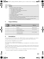
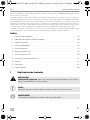
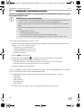
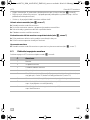
Table of contents
1 Description of symbols. . . . . . . . . . . . . . . . . . . . . . . . . . . . . . . . . . . . . . . . . . . . . . . . . . . . . . . 9
2 Safety and installation instructions . . . . . . . . . . . . . . . . . . . . . . . . . . . . . . . . . . . . . . . . . . . . . 10
3 Scope of delivery . . . . . . . . . . . . . . . . . . . . . . . . . . . . . . . . . . . . . . . . . . . . . . . . . . . . . . . . . . 12
4 Intended use . . . . . . . . . . . . . . . . . . . . . . . . . . . . . . . . . . . . . . . . . . . . . . . . . . . . . . . . . . . . . . 12
5 Technical description . . . . . . . . . . . . . . . . . . . . . . . . . . . . . . . . . . . . . . . . . . . . . . . . . . . . . . . 13
6 Installing the LCD monitor . . . . . . . . . . . . . . . . . . . . . . . . . . . . . . . . . . . . . . . . . . . . . . . . . . . 14
7 Using the LCD monitor . . . . . . . . . . . . . . . . . . . . . . . . . . . . . . . . . . . . . . . . . . . . . . . . . . . . . . 17
8 Cleaning and maintaining the LCD monitor . . . . . . . . . . . . . . . . . . . . . . . . . . . . . . . . . . . . . 18
9 Warranty . . . . . . . . . . . . . . . . . . . . . . . . . . . . . . . . . . . . . . . . . . . . . . . . . . . . . . . . . . . . . . . . . 19
10 Disposal. . . . . . . . . . . . . . . . . . . . . . . . . . . . . . . . . . . . . . . . . . . . . . . . . . . . . . . . . . . . . . . . . . 19
11 Technical data. . . . . . . . . . . . . . . . . . . . . . . . . . . . . . . . . . . . . . . . . . . . . . . . . . . . . . . . . . . . . 19
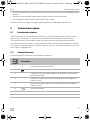
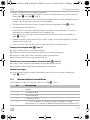
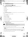
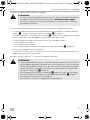
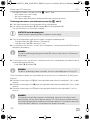
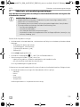
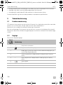
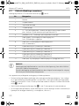
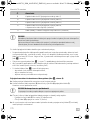
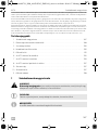
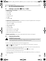
1 Description of symbols
!
A
I
CAUTION!
Safety instruction: Indicates a hazardous situation that, if not avoided, could result in
minor or moderate injury.
NOTICE!
Indicates a situation that, if not avoided, can result in property damage.
NOTE
Supplementary information for operating the product.
DometicM71L_IOM_4445102563_EMEA16_xxxx-xx-xx.book Seite 9 Montag, 12. April 2021 4:22 16

Safety and installation instructions M71L
EN
10
2 Safety and installation instructions
Please observe the prescribed safety instructions and stipulations from the vehicle
manufacturer and service workshops.
A
Therefore, please observe the following instructions:
• When working on the following cables, only use insulated cable lugs, plugs and tab sleeves:
– 30 (direct input from positive battery terminal)
– 15 (connected positive terminal, behind the battery)
– 31 (return cable from the battery, earth)
– 58 (reversing light)
Do not use porcelain wire connectors.
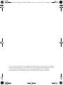
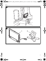
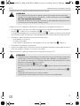
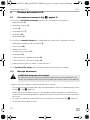
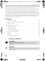
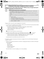
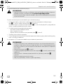
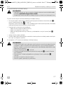
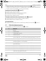
• Use a crimping tool (fig. 1 12, page 3) to connect the cables.
• Screw the cable when connecting cable 31 (earth)
– Screw on the cable using a cable lug and gear disc to one of the vehicle's earth bolts or
– Screw the cable to the sheet metal body work using a cable lug and a self-tapping screw.
Make sure there is a good earth connection.
If you disconnect the negative terminal of the battery, all data stored in the comfort electronics vol-
atile memory will be lost.
• The following data must be reset, depending on the vehicle equipment options:
–Radio code
–Vehicle clock
–Timer
– On-board computer
–Seat position
You can find instructions for making these settings in the operating manual.
NOTICE! Risk of damage!
• To prevent the danger of short circuiting, always disconnect the negative terminal
of the vehicle's electrical system before working on it.
If the vehicle has an additional battery, its negative terminal should also be discon-
nected.
• Inadequate supply line connections could result in short circuits, causing:
–Cable fires
– The airbag being triggered
– Damage to electronic control devices
– Electrical malfunctions (indicators, brake light, horn, ignition, lights)
DometicM71L_IOM_4445102563_EMEA16_xxxx-xx-xx.book Seite 10 Montag, 12. April 2021 4:22 16

M71L Safety and installation instructions
EN
11
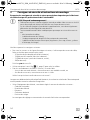
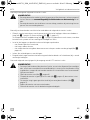
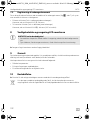
Note the following instructions during installation:
!
Observe the following instructions when working with electrical parts:
• When testing the voltage in electrical cables, only use a diode test lamp (fig. 1 1, page 3) or a
voltmeter (fig. 1 2, page 3).
Test lamps with a bulb (fig. 1 3, page 3) consume voltages which are too high and can dam-
age the vehicle's electronic system.
• When making electrical connections, ensure that:
– They are not kinked or twisted
– They do not rub on edges
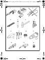
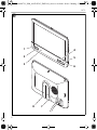
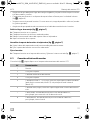
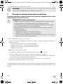
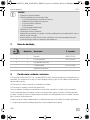
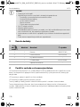
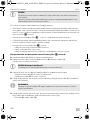
– They are not laid in sharp-edged through-holes without protection (fig. 3, page 4)
• Insulate all connections.
• Secure the cables against mechanical stress with cable binders or insulating tape, for example,
to existing lines.
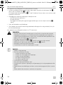
Observe the following instructions when handling the LCD monitor:
!
CAUTION!
• Secure the monitor in such a way that it cannot become loose under any circum-
stances (sudden braking, accidents) and cause injuries to the occupants of the
vehicle.
• Do not attach the monitor in the air bag deployment path, as this could cause injury
if the airbags are triggered.
CAUTION!
• People (including children) whose physical, sensory or mental capacities or whose
lack of experience or knowledge prevent them from using this product safely
should not use it without the supervision or instruction of a responsible person.
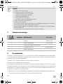
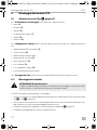
• Do not open the monitor (fig. 4, page 4).
• Do not immerse the monitor in water (fig. 5, page 4); the monitor is not water-
proof.
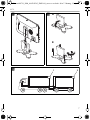
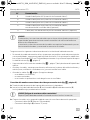
• The monitor must not impair your vision when driving (fig. 8, page 5).
• Do not operate the monitor with wet hands.
• Do not operate the monitor if the housing has been damaged.
DometicM71L_IOM_4445102563_EMEA16_xxxx-xx-xx.book Seite 11 Montag, 12. April 2021 4:22 16

Scope of delivery M71L
EN
12
A
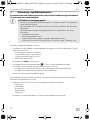
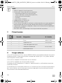
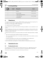
3Scope of delivery
4Intended use
The PerfectView M71LLCD monitor (ref no. 9600011060) is primarily intended for use in vehicles.
It can be used to connect cameras (e.g. a reversing video system) or other video sources.
The LCD monitor is designed for use in all vehicles.
The LCD monitor is suitable for commercial use.
This product is only suitable for the intended purpose and application in accordance with these
instructions.
This manual provides information that is necessary for proper installation and/or operation of the
product. Poor installation and/or improper operating or maintenance will result in unsatisfactory
performance and a possible failure.
The manufacturer accepts no liability for any injury or damage to the product resulting from:
• Incorrect assembly or connection, including excess voltage
NOTICE!
• Connect it to the correct voltage.
• Do not use the monitor in areas which:
– Are subject to direct sunlight
– Are subject to strong temperature fluctuations
– Have high levels of humidity
– Are poorly ventilated
– Are dusty or oily
• Do not press against the LCD display.
• Do not drop the monitor.
• If you use the monitor in vehicles, the vehicle should be running during operation to
prevent the vehicle battery from discharging.
• The picture quality can be impaired in the vicinity of electromagnetic fields.
For this reason do not mount the monitor near loudspeakers.
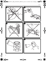
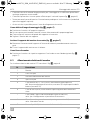
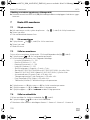
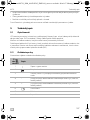
No. in
fig. 9,
page 5
Quantity Description Ref. no.
1 1 Monitor 9600011060
2 1 Monitor bracket 9102200193
3 1 Monitor bracket cover –
– 1 Connection cable 9102200056
––Fastening material –
DometicM71L_IOM_4445102563_EMEA16_xxxx-xx-xx.book Seite 12 Montag, 12. April 2021 4:22 16

M71L Technical description
EN
13
• Incorrect maintenance or use of spare parts other than original spare parts provided by the man-
ufacturer
• Alterations to the product without express permission from the manufacturer
• Use for purposes other than those described in this manual
Dometic reserves the right to change product appearance and product specifications.
5 Technical description
5.1 Function description
The LCD monitor can be connected to cameras (e.g. reversing video systems) or other video
sources (e.g. DVD players). It is possible to switch back and forth between video sources.
The monitor features control cables which allow the cameras to be activated automatically.
It can operate up to four cameras, which can be activated via external control cables or manually.
This monitor also features a distance grid in the display which is activated automatically when the
reverse gear is engaged (AV1).
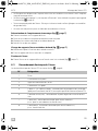
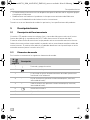
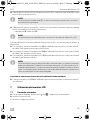
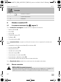
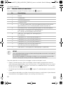
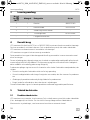
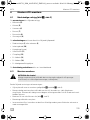
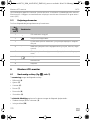
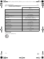
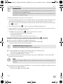
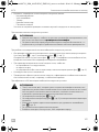
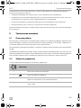
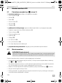
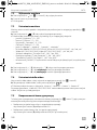
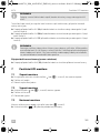
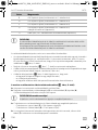
5.2 Control elements
The following control elements are located on the monitor:
No. in
fig. 0,
page 6
Description
1 Switches the monitor on and off.
2 Switches to setup mode.
3 The light sensor automatically adjusts the brightness of the display
to the ambient light.
4 – Reduces the audio volume or the selected parameter (brightness,
contrast, color).
5 + Increases the audio volume or the selected parameter (brightness,
contrast, color).
6 Selects the camera.
7Monitor bracket
8 Loudspeaker
DometicM71L_IOM_4445102563_EMEA16_xxxx-xx-xx.book Seite 13 Montag, 12. April 2021 4:22 16

Installing the LCD monitor M71L
EN
14
6 Installing the LCD monitor
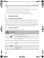
6.1 Tools required (fig. 1, page 3)
For installation and assembly you will need the following tools:
• Measuring ruler (4)
•Center punch (5)
•Hammer (6)
• Drill head set (7)
• Drill (8)
• Screwdriver (9)
To establish and test the electrical connection, the following tools are required:
•Diode test lamp (1) or voltmeter (2)
•Insulating tape (10)
• Heat shrinking sleeve
• Hot air blower (11)
• Crimping tool (12)
• Soldering iron (optional) (13)
• Solder (optional) (14)
• Cable bushing sleeves (optional)
To fasten the cables, you may require additional cable binders.
6.2 Installing the monitor
!
Note the following instructions during installation:
• Select an installation location that provides an unobstructed view of the monitor (fig. 6 and
fig. 7, page 4).
• Never install the monitor in areas where your head could hit it or in the airbag deployment path.
This could cause injury if the airbag opens.
• The monitor must not impair your vision when driving (fig. 8, page 5).
• The installation location should be flat.
• Check that there is sufficient space underneath the installation location to attach the washers
and nuts.
CAUTION! Beware of injury!
Select the location of the monitor so that it cannot injure the passengers in the vehicle
under any circumstances (e.g. sudden braking, road traffic accidents).
DometicM71L_IOM_4445102563_EMEA16_xxxx-xx-xx.book Seite 14 Montag, 12. April 2021 4:22 16

M71L Installing the LCD monitor
EN
15
• Check beforehand that there is sufficient space on the other side for the drill head to come out
(fig. 2, page 4).
• Bear in mind the weight of the monitor. Provide reinforcement if necessary (larger washers or
plates).
• Make sure you can lay the connection cable to the monitor.
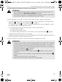
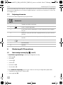
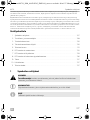
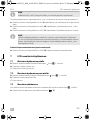
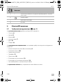
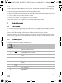
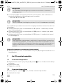
Choosing the installation location (fig. a, page 7)
➤ Place the monitor on the monitor bracket.
➤ Position the monitor and the attached monitor bracket provisionally.
➤ Mark the outlines of the corners of the support base on the dashboard.
➤ Take the monitor off the monitor bracket.
Screwing the monitor bracket onto the dashboard (fig. b, page 7)
➤ Hold the support base within the outlines marked beforehand.
➤ Fix the monitor bracket in place using suitable screws.
Fastening the monitor
➤ Set the monitor on the monitor bracket and secure it with the knurled nut (fig. a, page 7).
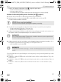
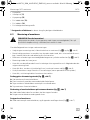
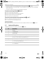
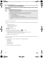
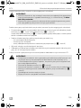
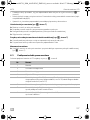
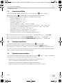
6.3 Connecting the monitor electrically
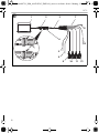
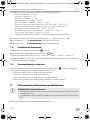
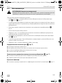
The circuit diagram for the LCD monitor can be found in fig. d, page 8.
No. Description
1Monitor
220-pin socket
3 Monitor line
4 20-pin plug
5 12 – 24 V positive cable (red): connected to the positive terminal of the
ignition (connected positive, terminal 15) or the positive terminal of the bat-
tery (terminal 30)
6 Earth cable (black): connected to the negative terminal of the voltage
source
7 Cable (green): control input for video input AV1,
such as for connecting the reversing light
8 Cable (white): control input for video input AV2,
such as for the side camera
DometicM71L_IOM_4445102563_EMEA16_xxxx-xx-xx.book Seite 15 Montag, 12. April 2021 4:22 16

Installing the LCD monitor M71L
EN
16
A
Observe the following instructions when laying the connection cables:
• If possible, use existing through-holes for feeding through the connection cables, or other suit-
able options, such as ventilation grilles. If there are no existing through-holes, you must drill a
hole of ∅ 22 mm. Check beforehand that there is sufficient space on the other side for the drill
head to emerge (fig. 2, page 4).
• Cover the holes with the feed through (fig. b 1, page 7) in the base of the monitor bracket.
• To prevent damage to the cables, when laying them ensure that there is always a sufficient dis-
tance to vehicle components which can become hot (lights, heaters, ventilators etc.).
• When laying the cables (fig. 3, page 4), make sure:
– They are not kinked or twisted
– They do not rub on edges
– They are not laid in sharp-edged through-holes without protection
Connecting the monitor as a reversing video system (fig. d, page 8)
➤ Lay the connection cable for the monitor bracket on the dashboard.
➤ Insert the plug of the monitor cable (2) into the socket (4) of the connection cable (3).
Wait until you hear the plug snap in.
A
➤ Connect the red and black cables of the connection cable to a suitable voltage supply:
– Connect the red cable (5) to terminal 15 (ignition).
– Connect the black cable (6) to terminal 31 (earth).
➤ If the monitor is to be activated when reverse gear is selected, connect the green cable (7) to
the positive cable of the reversing light.
9 6-pin AV1 socket (connection to video source 1)
10 6-pin AV2 socket (connection to video source 2)
11 6-pin AV3 socket (connection to video source 3)
12 6-pin AV4 socket (connection to video source 4,
with video signal detection) (optional)
13 Cable (blue): control input for video input AV3 (optional)
NOTICE!
Cables and cable connections that are not properly installed will cause malfunctions or
damage to components.
Correct installation of cables and cable connections ensures lasting and trouble-free
operation of the retrofitted components.
NOTICE! Risk of damage!
Make sure the polarity is correct when connecting to a voltage source.
No. Description
DometicM71L_IOM_4445102563_EMEA16_xxxx-xx-xx.book Seite 16 Montag, 12. April 2021 4:22 16

M71L Using the LCD monitor
EN
17
I
➤ If the monitor is to be activated e.g. when the indicator is flashing, connect the following control
cable to a positive cable of the indicator:
–white cable (8), blue cable (13)
I
This control cable is used as a signal cable for the activation of a side camera when an indicator is
flashing, for example.
➤ If necessary, connect the AV1 socket (9) of the connection cable to the plug of video source 1
(e.g. reversing camera).
➤ If necessary, connect the AV2 socket (10) of the connection cable to the plug of the video
source 2 (e.g. side camera).
➤ If necessary, connect the AV3 socket (11) of the connection cable to the plug of video source 3
(e.g. camera).
I
Connecting an additional reversing camera (trailer operation)
➤ If necessary, connect socket AV4 (12) of the connection cable to the plug of the additional
reversing camera.
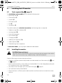
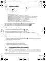
7 Using the LCD monitor
7.1 Switching on the monitor
➤ If the monitor is switched off, press the button (fig. 0 2, page 6) to switch the monitor on.
➤ The button lights up blue.
✔ The picture appears.
7.2 Switching off the monitor
➤ Press the button (fig. 0 2, page 6) to switch off the monitor.
➤ The button lights up red.
✔ The picture disappears.
NOTE
If voltage is present at the green cable (7), the reversing camera is activated. The
reversing camera has priority.
NOTE
If voltage is present in this control cable, the video inputs AV2 and AV3 will be acti-
vated.
NOTE
Observe the power consumption of the video system. The cameras are equipped with
heaters. A maximum current of 1.5 A can flow (three cameras in heating mode). Use a
disconnecter switch for direct connection to the battery. This allows you to disconnect
the video system from the battery easily if you are no longer using the vehicle.
DometicM71L_IOM_4445102563_EMEA16_xxxx-xx-xx.book Seite 17 Montag, 12. April 2021 4:22 16

Cleaning and maintaining the LCD monitor M71L
EN
18
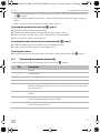
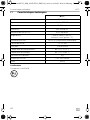
7.3 Setting the monitor
To set the monitor to suit your requirements, proceed as follows (fig. 0, page 6):
➤ Press the “ ” button (5) to call up the required parameter.
✔ The parameters to be set are displayed in the following sequence:
– Brightness: 0 – 100
– Contrast: 0 – 100
– Saturation: 0 – 100
– Volume: 0 – 100
– Language: English, French, German
– Mirror AV1/AV2/AV3/AV4: Yes or No
– Video AV1/AV2/AV3/AV4: Yes or No
– Distance grid: ON or OFF
– Trailer detection: ON or OFF
– Day/night mode: ON or OFF
– Default: Default setting for all parameters
➤ Press the “+” button (3) or the “–” button (4) to set the required parameter.
➤ Press the “+” button (3) to increase the value of the selected parameter.
➤ Press the “–” button (4) to reduce the value of the selected parameter.
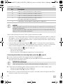
7.4 Setting the video source
Proceed as follows to set the video source (fig. 0, page 6):
➤ If you would like to switch to a different video source, press the button (6).
✔ The monitor changes the camera in the order Camera 1 – Camera 2 – Camera 3 – Camera 4.
With the Video AV1/AV2/AV3/AV4 parameter, video inputs that are not used can be switched to
inactive. These empty inputs are then skipped over.
7.5 Detecting the trailer camera
This function is required when using a trailer camera (fig. c, page 7) if the system is activated auto-
matically via the reverse gear.
• One camera connected (e.g. towing vehicle without a trailer):
the camera connected to AV1 (1) is activated.
• Two cameras connected (e.g. towing vehicle with a trailer):
the camera connected to AV4 (2) is activated (AV1 is inactive).
8 Cleaning and maintaining the LCD monitor
A
➤ Clean the monitor with a soft, damp cloth from time to time.
NOTICE! Risk of damage!
• Do not use sharp or hard objects for cleaning, as these may damage the monitor.
• Remove the cable before cleaning the monitor to prevent short circuiting.
DometicM71L_IOM_4445102563_EMEA16_xxxx-xx-xx.book Seite 18 Montag, 12. April 2021 4:22 16

M71L Warranty
EN
19
9Warranty
The statutory warranty period applies. If the product is defective, please contact the
manufacturer's branch in your country (see dometic.com/dealer) or your retailer.
For repair and warranty processing, please send the following items:
• Defect components
• A copy of the receipt with purchasing date
• A reason for the claim or description of the fault
10 Disposal
➤ Place the packaging material in the appropriate recycling waste bins, wherever possible.
M
If you wish to finally dispose of the product, ask your local recycling center or specialist
dealer for details about how to do this in accordance with the applicable disposal
regulations.
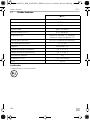
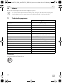
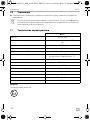
11 Technical data
M71L
Ref. no.: 9600011060
Type: Color TFT LCD
Display size: 7" (17.8 cm)
Brightness: Approx. 500 cd/m²
Display resolution, H x V: 800 x 480 pixels
Viewing angle: vertical: above 50°, below 70°,
horizontal: right/left: 70°
Television standard: PAL/NTSC (automatic switching)
Operating voltage: 12 – 32 Vg
Output: maximum 10 W
Operating temperature: –20 °C to +70 °C
Storage temperature: –30 °C to +80 °C
Vibration resistance: 6 g
Dimensions W x H x D: 174 x 125 x 26 mm
Weight: 400 g
DometicM71L_IOM_4445102563_EMEA16_xxxx-xx-xx.book Seite 19 Montag, 12. April 2021 4:22 16

Technical data M71L
EN
20
Certifications
This device has E8 approval.
8
DometicM71L_IOM_4445102563_EMEA16_xxxx-xx-xx.book Seite 20 Montag, 12. April 2021 4:22 16
Seite wird geladen ...
Seite wird geladen ...
Seite wird geladen ...
Seite wird geladen ...
Seite wird geladen ...
Seite wird geladen ...
Seite wird geladen ...
Seite wird geladen ...
Seite wird geladen ...
Seite wird geladen ...
Seite wird geladen ...
Seite wird geladen ...
Seite wird geladen ...
Seite wird geladen ...
Seite wird geladen ...
Seite wird geladen ...
Seite wird geladen ...
Seite wird geladen ...
Seite wird geladen ...
Seite wird geladen ...
Seite wird geladen ...
Seite wird geladen ...
Seite wird geladen ...
Seite wird geladen ...
Seite wird geladen ...
Seite wird geladen ...
Seite wird geladen ...
Seite wird geladen ...
Seite wird geladen ...
Seite wird geladen ...
Seite wird geladen ...
Seite wird geladen ...
Seite wird geladen ...
Seite wird geladen ...
Seite wird geladen ...
Seite wird geladen ...
Seite wird geladen ...
Seite wird geladen ...
Seite wird geladen ...
Seite wird geladen ...
Seite wird geladen ...
Seite wird geladen ...
Seite wird geladen ...
Seite wird geladen ...
Seite wird geladen ...
Seite wird geladen ...
Seite wird geladen ...
Seite wird geladen ...
Seite wird geladen ...
Seite wird geladen ...
Seite wird geladen ...
Seite wird geladen ...
Seite wird geladen ...
Seite wird geladen ...
Seite wird geladen ...
Seite wird geladen ...
Seite wird geladen ...
Seite wird geladen ...
Seite wird geladen ...
Seite wird geladen ...
Seite wird geladen ...
Seite wird geladen ...
Seite wird geladen ...
Seite wird geladen ...
Seite wird geladen ...
Seite wird geladen ...
Seite wird geladen ...
Seite wird geladen ...
Seite wird geladen ...
Seite wird geladen ...
Seite wird geladen ...
Seite wird geladen ...
Seite wird geladen ...
Seite wird geladen ...
Seite wird geladen ...
Seite wird geladen ...
Seite wird geladen ...
Seite wird geladen ...
Seite wird geladen ...
Seite wird geladen ...
Seite wird geladen ...
Seite wird geladen ...
Seite wird geladen ...
Seite wird geladen ...
Seite wird geladen ...
Seite wird geladen ...
Seite wird geladen ...
Seite wird geladen ...
Seite wird geladen ...
Seite wird geladen ...
Seite wird geladen ...
Seite wird geladen ...
Seite wird geladen ...
Seite wird geladen ...
Seite wird geladen ...
Seite wird geladen ...
Seite wird geladen ...
Seite wird geladen ...
Seite wird geladen ...
Seite wird geladen ...
Seite wird geladen ...
Seite wird geladen ...
Seite wird geladen ...
Seite wird geladen ...
Seite wird geladen ...
Seite wird geladen ...
Seite wird geladen ...
Seite wird geladen ...
Seite wird geladen ...
Seite wird geladen ...
Seite wird geladen ...
Seite wird geladen ...
Seite wird geladen ...
Seite wird geladen ...
Seite wird geladen ...
Seite wird geladen ...
Seite wird geladen ...
Seite wird geladen ...
Seite wird geladen ...
Seite wird geladen ...
Seite wird geladen ...
Seite wird geladen ...
Seite wird geladen ...
Seite wird geladen ...
Seite wird geladen ...
Seite wird geladen ...
Seite wird geladen ...
Seite wird geladen ...
Seite wird geladen ...
Seite wird geladen ...
Seite wird geladen ...
Seite wird geladen ...
Seite wird geladen ...
Seite wird geladen ...
Seite wird geladen ...
Seite wird geladen ...
Seite wird geladen ...
Seite wird geladen ...
Seite wird geladen ...
Seite wird geladen ...
Seite wird geladen ...
Seite wird geladen ...
Seite wird geladen ...
Seite wird geladen ...
Seite wird geladen ...
Seite wird geladen ...
Seite wird geladen ...
Seite wird geladen ...
Seite wird geladen ...
Seite wird geladen ...
Seite wird geladen ...
Seite wird geladen ...
Seite wird geladen ...
Seite wird geladen ...
Seite wird geladen ...
Seite wird geladen ...
Seite wird geladen ...
Seite wird geladen ...
Seite wird geladen ...
Seite wird geladen ...
Seite wird geladen ...
Seite wird geladen ...
Seite wird geladen ...
Seite wird geladen ...
Seite wird geladen ...
Seite wird geladen ...
Seite wird geladen ...
Seite wird geladen ...
Seite wird geladen ...
Seite wird geladen ...
Seite wird geladen ...
Seite wird geladen ...
Seite wird geladen ...
Seite wird geladen ...
Seite wird geladen ...
Seite wird geladen ...
Seite wird geladen ...
Seite wird geladen ...
Seite wird geladen ...
Seite wird geladen ...
-
 1
1
-
 2
2
-
 3
3
-
 4
4
-
 5
5
-
 6
6
-
 7
7
-
 8
8
-
 9
9
-
 10
10
-
 11
11
-
 12
12
-
 13
13
-
 14
14
-
 15
15
-
 16
16
-
 17
17
-
 18
18
-
 19
19
-
 20
20
-
 21
21
-
 22
22
-
 23
23
-
 24
24
-
 25
25
-
 26
26
-
 27
27
-
 28
28
-
 29
29
-
 30
30
-
 31
31
-
 32
32
-
 33
33
-
 34
34
-
 35
35
-
 36
36
-
 37
37
-
 38
38
-
 39
39
-
 40
40
-
 41
41
-
 42
42
-
 43
43
-
 44
44
-
 45
45
-
 46
46
-
 47
47
-
 48
48
-
 49
49
-
 50
50
-
 51
51
-
 52
52
-
 53
53
-
 54
54
-
 55
55
-
 56
56
-
 57
57
-
 58
58
-
 59
59
-
 60
60
-
 61
61
-
 62
62
-
 63
63
-
 64
64
-
 65
65
-
 66
66
-
 67
67
-
 68
68
-
 69
69
-
 70
70
-
 71
71
-
 72
72
-
 73
73
-
 74
74
-
 75
75
-
 76
76
-
 77
77
-
 78
78
-
 79
79
-
 80
80
-
 81
81
-
 82
82
-
 83
83
-
 84
84
-
 85
85
-
 86
86
-
 87
87
-
 88
88
-
 89
89
-
 90
90
-
 91
91
-
 92
92
-
 93
93
-
 94
94
-
 95
95
-
 96
96
-
 97
97
-
 98
98
-
 99
99
-
 100
100
-
 101
101
-
 102
102
-
 103
103
-
 104
104
-
 105
105
-
 106
106
-
 107
107
-
 108
108
-
 109
109
-
 110
110
-
 111
111
-
 112
112
-
 113
113
-
 114
114
-
 115
115
-
 116
116
-
 117
117
-
 118
118
-
 119
119
-
 120
120
-
 121
121
-
 122
122
-
 123
123
-
 124
124
-
 125
125
-
 126
126
-
 127
127
-
 128
128
-
 129
129
-
 130
130
-
 131
131
-
 132
132
-
 133
133
-
 134
134
-
 135
135
-
 136
136
-
 137
137
-
 138
138
-
 139
139
-
 140
140
-
 141
141
-
 142
142
-
 143
143
-
 144
144
-
 145
145
-
 146
146
-
 147
147
-
 148
148
-
 149
149
-
 150
150
-
 151
151
-
 152
152
-
 153
153
-
 154
154
-
 155
155
-
 156
156
-
 157
157
-
 158
158
-
 159
159
-
 160
160
-
 161
161
-
 162
162
-
 163
163
-
 164
164
-
 165
165
-
 166
166
-
 167
167
-
 168
168
-
 169
169
-
 170
170
-
 171
171
-
 172
172
-
 173
173
-
 174
174
-
 175
175
-
 176
176
-
 177
177
-
 178
178
-
 179
179
-
 180
180
-
 181
181
-
 182
182
-
 183
183
-
 184
184
-
 185
185
-
 186
186
-
 187
187
-
 188
188
-
 189
189
-
 190
190
-
 191
191
-
 192
192
-
 193
193
-
 194
194
-
 195
195
-
 196
196
-
 197
197
-
 198
198
-
 199
199
-
 200
200


in anderen Sprachen
- English: Dometic M71L Operating instructions
- français: Dometic M71L Mode d'emploi
- español: Dometic M71L Instrucciones de operación
- italiano: Dometic M71L Istruzioni per l'uso
- русский: Dometic M71L Инструкция по эксплуатации
- Nederlands: Dometic M71L Handleiding
- slovenčina: Dometic M71L Návod na používanie
- português: Dometic M71L Instruções de operação
- dansk: Dometic M71L Betjeningsvejledning
- polski: Dometic M71L Instrukcja obsługi
- čeština: Dometic M71L Operativní instrukce
- svenska: Dometic M71L Bruksanvisningar
- suomi: Dometic M71L Käyttö ohjeet
Verwandte Artikel
-
Dometic CAM360AHD Installationsanleitung
-
Dometic M71L Bedienungsanleitung
-
-
-
-
-
-
-
Dometic CFX3 Benutzerhandbuch
-
Dometic MCK750 Bedienungsanleitung