ROBBE Air Beaver Instruction And User's Manual
- Typ
- Instruction And User's Manual

www.robbe.com
V1_06/2019
BAU- UND BETRIEBSANLEITUNG
INSTRUCTIONS AND USER MANUAL
MANUEL D´UTILISATION
Schwimmer-Set Air Beaver
Nr.: 25691000

DEUTSCH
2
SCHWIMMER-SET
BAU- UND BETRIEBSANLEITUNG
Das Modell im Wasser mit langsam Gas aus dem Uferbe-
reich fahren. Motor abschalten, das Modell stellt sich in
die Windrichtung (gegen den Wind).
Gas geben und Modell beschleunigen lassen, bis es auf
die Schwimmerstufen kommt und in Gleitfahrt übergeht.
Das Höhenruder bleibt zunächst in Startstellung „neu-
tral“. Erst beim Abwassern leicht ziehen.
Die Beaver wird, bedingt durch den erhöhten Luftwider-
stand, in der Flugphase etwas träger reagieren und et-
was mehr Gas benötigen. Dies beim Fliegen und bei der
Landeeinteilung berücksichtigen.
Zur Wasserung mit ausreichend Schleppgas gleichmä-
ßig sinken und das Modell aufsetzen lassen.
Den Flug rechtzeitig beenden, um mit genügend Rest-
strom zur Startstelle zurückzukehren.
Nach Beendigung des Wasserugbetriebs das Modell
öffnen und auf eventuell eingedrungenes Spritzwasser
kontrollieren. Falls erforderlich, Modell trocknen lassen.
Von Zeit zu Zeit Schwimmer und Ruderanlage kontrollie-
ren, ob keine Schäden durch Treibgut aufgetreten sind.
Inhalt Seite
Technische Daten / Allgemeine Hinweise 2
Vorbereitungen 2
Bauanleitung 5, 6, 7, 8
Technische Daten
Schwimmerlänge: ca. 690 mm
Gesamtbreite: ca. 435 mm
Das robbe Schwimmerset ist vorgesehen für das Modell
Air Beaver, eignet sich aber auch für Modelle ähnlicher
Größe und mit ähnlichem Gewicht zum Umrüsten auf
Wasserflug.
Die Schwimmer-Einheit kann nach Abnehmen des
Beaver-Radfahrwerks direkt am Rumpf montiert wer-
den, zusätzliche Veränderungen sind nicht erforderlich.
Ebenso ist es jederzeit möglich, die montierten
Schwimmer wieder abzunehmen und auf ein
Radfahrwerk zurückzurüsten.
Allgemeine Hinweise für den Bauablauf
Verschaffen Sie sich in Verbindung mit den Abbildungen
und den dazugehörigen Kurztexten einen Überblick
über die jeweiligen Bauschritte.
Klebearbeiten sind nicht erforderlich. Die Einzelteile wer-
den zusammengeschraubt.
Funktionsprobe
Beim startbereiten Modell den Schwerpunkt erneut
kontrollieren.
Alle Ruder und den Motor überprüfen, die Wasserruder
auf einwandfreie Funktion kontrollieren.
Vor dem ersten Wasserstart sollte das Modell einwand-
frei eingeogen und ausgetrimmt sein.
Hinweis zum Flugbetrieb, der erste Wasserstart
Alle Sicherheitshinweise beachten, zusätzlich beson-
ders berücksichtigen, dass keine anderen Nutzer des
Gewässers (Schwimmer, Bootfahrer etc.) gefährdet
werden können.
Ein ausreichend großes Gewässer und einen windstil-
len Tag für die ersten Wasserstarts auswählen. Bedingt
durch die Zusatzruder an den Schwimmern ist das Mo-
dell im Wasser gut manövrierbar.
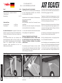
Verkleidungen vorsichtig lösen und abnehmen. Schrauben der Tragflächenstreben lösen, Streben
abnehmen.
Schrauben der Fahrwerke lösen, Fahrwerke abnehmen.
Vorbereitungen

ENGLISH
3
FLOATS SET
INSTRUCTIONS AND USER MANUAL
thercocking effect).
Open the throttle and allow the aeroplane to accele-
rate until it rises onto the step of the oats, and starts
planing.
Leave the elevator at the "neutral" position initially. Do
not apply up-elevator until you actually wish to lift off.
The increased drag caused by the oats causes the
Beaver to respond a little more slowly in the air, and it
will require a slightly higher throttle setting. Take this into
account when ying the model, and preparing for the
landing.
Allow the model to descend steadily by keeping power
on to a higher level than normal, and allow the aero-
plane to touch down smoothly on the water.
Bring the ight to a close in good time, so that you have
enough residual current to taxi back to the bank.
At the end of the water ying session open the fuselage
and check for any water inside. Allow the model to dry
out if necessary.
From time to time check that the oats and rudder sys-
tem have not been damaged by otsam in the water.
Contents Page
Technical specication / general information 3
Preparations 3
Building Instructions 5, 6, 7, 8
Specification
Float length: approx. 690 mm
Overall width: approx. 435 mm
The robbe floats set is designed for the Air Beaver model
aircraft, but is also suitable for converting other models
of similar size and weight for flying from water.
Once the Beaver's standard wheeled undercarriage
has been removed, the floats assembly can be atta-
ched directly to the fuselage; no other modifications
are required.
It is also possible at any time to remove the floats
assembly and convert the model back to wheels again.
Sequence of assembly
Please study the illustrations and the brief instructions to
obtain a clear understanding of the individual stages of
construction.
No glued joints are required. All the component parts
are screwed together.
Function test
The converted model's Centre of Gravity should be
checked before the first flight.
Check all the control surfaces and the power system,
and ensure that the water rudders work correctly.
The model should be test-own and trimmed properly
before it is tted with oats and own from water.
Notes on flying the model; the first take-off from water
Observe all the safety notes, but please ensure in par-
ticular that you do not endanger any other users of the
water (bathers, boat operators, etc.).
For the rst few test-ights using the oats, seek out an
area of calm water of adequate size, and wait for a day
with little or no wind. The model is easy to manoeuvre
on the water thanks to the supplementary rudders atta-
ched to the oats.
Place the model in the water and open the throttle gra-
dually to taxi away from the bank. Switch off the motor,
and the model will automatically swing into wind (wea-
Carefully undo the undercarriage fairings and remove
them.
Undo the screws retaining the wing struts, and remove
the struts.
Undo the undercarriage retaining screws, and remove
the complete undercarriage.
Preparations

FRANÇAIS
4
KIT DE FLOTTEURS
MANUEL D´UTILISATION
Sommaire Page
Caractéristiques techniques / Consignes générales 4
Préparatifs 4
Notice de construction 5, 6, 7, 8
Caractéristiques techniques
Longueur du flotteur: approx. 690 mm
Largeur totale: approx. 435 mm
Le kit flotteurs est conçu pour le modèle Air Beaver, il
convient toutefois également à des modèle de taille
et de poids similaires pour leur transformation en hydra-
vion.
Il est possible de monter directement l‘unité flotteurs
sur le fuselage après avoir retiré l‘atterrisseur du Beaver,
d‘autres transformations ne sont pas nécessaires.
Il est également à tout moment possible de retirer à
nouveau les flotteurs et de rétablir l‘atterrisseur à roue.
Généralités concernant le déroulement de la construc-
tion
Avant d‘entreprendre la construction du modèle, lire
les textes de la notice au regard des illustrations afin de
vous forger une vue d‘ensemble des différentes étapes
de la construction.
Aucun collage n‘est indispensable. Les éléments indivi-
duels sont vissés les uns aux autres.
Essai des fonctions
Recontrôlez le centre de gravité du modèle prêt à
décoller.
Contrôlez toutes les gouvernes et le moteur, vérifier que
les gouvernails des flotteurs fonctionnent parfaitement.
Avant le premier décollage il faut que le modèle ait
déjà volé avec des roues et qu‘il soit parfaitement
équilibré.
Consignes de vol, le premier décollage de l‘eau
Respectez toutes les consignes de sécurité et veillez
particulièrement à ne mettre personne en danger sur le
plan d‘eau (nageur, personnes en calot, etc.).
Choisissez un plan d‘eau relativement étendu et un jour
sans vent pour le premier décollage de l‘eau. Grâce
aux gouvernail solidaires des otteurs le modèle offre
une excellente manoeuvrabilité sur l‘eau.
Éloignez le modèle de la berge en donnant lentement
des gaz. Coupez le moteur, le modèle s‘installe contre
le vent.
Donnez des gaz et accélérez le modèle jusqu‘á ce qu‘il
vienne sur l‘arrière des otteurs et glisse sur l‘eau.
La gouvernede profondeur rested‘abord en position de
démarrage, c‘est-à-dure au „neutre“. Tire légèrement
lorsque le modèle quitte l‘eau.
À cause de la résistance plus importante de l‘air, le Be-
aver réagira plus lentement dans sa phase de vol et il
faudra donner plus de gaz. Tenir compte de cette re-
marque pendant la phase de vol et à l‘atterrissage.
Pour atterrir sur l‘eau, laissez descendre le modèle ré-
gulièrement avec sufsamment de gaz de traînée et
posez-le sur l‘eau.
Interrompez le vol sufsamment tôt pour disposer de suf-
samment de courant pour revenir à la berge.
Une fois la séance de vol sur l‘eau terminée, ouvrez le
modèle et vériez qu‘il ne contient pas d‘eau. Si néces-
saire, laissez-le sécher.
De temps en temps vériez les otteurs et les gouver-
nails, ils risquent quelquefois d‘être endommagés par
des objets ottants.
Défaire le carénage avec précaution et retirez-le. Desserrer les vis des étais d'aile et retirez les étais. Desserrez les vis de l'atterrisseur, retirer les étais.
Préparatifs

DE/EN/FR
5
BAU- UND BETRIEBSANLEITUNG SCHWIMMERSET
BUILDING AND OPERATING INSTRUCTIONS FLOAT SET
NOTICE DE MONTAGE ET DE MISE EN OEUVRE DU KIT FLOTTEURS
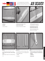
1 2 3
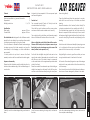
Bild / Fig. 1
- Lieferumfang
- Set contents
- Contenu de la livraison
Bild / Fig. 4
- Die Stützstreben zuordnen. Dazu die Bilder 5-7 beachten.
- Assign the support struts to the floats as shown, referring to
Figs. 5-7.
- Agencez les étais de soutien. Pour ce faire observez les fig.
5 à 7.
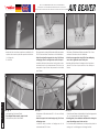
Bilder / Figs. 5 - 7
- Die Stützstreben sind an den Enden mit Kennungen versehen.
Diese Kennungen finden sich an den Aufhängungspunkten
auf den Schwimmern wieder.
L = linke Seite
R = rechte Seite
Bild / Fig. 2
- Die Querstreben in die Schwimmer schieben.
- Insert the cross-struts in the floats.
- Glissez les étais transversaux dans les flotteurs.
Bild / Fig. 3
- Auf deckungsgleiche Bohrungen achten.
- Gewindeschrauben M 2,4 x 20 eindrehen
- Ensure that the holes line up correctly.
- Fit the M2.4 x 20 mm machine screws.
- Veillez à ce que les alésages coïncident.
- Mettez les vis M 2,4 x 20 en place
4 5 6
B1L
M 2,4 x 20
Figs. 5 - 7
- The ends of the support struts feature identification marks.
You will also find matching marks at the attachment points
on the floats.
L = left hand side
R = right hand side

DE/EN/FR
6
BAU- UND BETRIEBSANLEITUNG SCHWIMMERSET
BUILDING AND OPERATING INSTRUCTIONS FLOAT SET
NOTICE DE MONTAGE ET DE MISE EN OEUVRE DU KIT FLOTTEURS
7 8 9
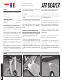
Bild / Fig. 10
- Montagefertige Schwimmer-Einheit.
- The completed floats assembly, ready to install.
- Unité de flotteur prête à être installée.
Bild / Fig. 11
- Stützstreben mit Blechschrauben Ø 3 x 16 mm am Rumpf
montieren.
- Attach the support struts to the fuselage using 3 Ø x16 mm
self-tapping screws.
- Montez les étais de soutien au fuselage avec les vis
autotaraudeuses Ø 3 x 16 mm.
Bild / Fig. 12
- Für die hinteren Streben sind beidseitig im Rumpf Montagepunkte
„M“ zum Verschrauben der Streben eingebaut.
- Mounting points „M“ are installed on both sides of the fuselage to
accept the retaining screws for the rear struts.
- Pour les étais arrière, bilatéralement, sont disposés des points de
montage „M“ sur le fuselage pour le vissage des étais.
Bild / Fig. 8
- Die zugeordneten vorderen Stützstreben mit Blechschrauben
Ø 2,4 x 8 mm montieren. Schrauben noch nicht festziehen.
- Attach the assigned front support struts using 2.4 Ø x 8 mm
self-tapping screws. Do not tighten the screws at this point.
- Montez les étais de soutien avant en fonction de leur ordon-
nancement avec les vis autotaraudeuses Ø 2,4 x 8 mm. Ne
serrez pas les vis pour l‘instant. Ne pas serrer les is du châssis
pour l’instant.
Bild / Fig. 9
- Die hinteren Stützstreben mit Blechschrauben Ø 2,4 x 8 mm
montieren. Schrauben noch nicht festziehen.
- Attach the rear support struts using 2.4 Ø x 8 mm selftapping
screws. Do not tighten the screws at this point.
- Montez les étais de soutien au fuselage avec les vis autotarau-
deuses Ø 2,4 x 8 mm. Ne pas serrer les vis du châssis pour
l’instant.
10 11
12
B2L
Ø 2,4 x 8
Ø 2,4 x 8
Ø 3 x 16
„M“
Ø 3 x 16
Fig. 5 à 7
- Munissez les étais de soutien de repères aux extrémités. Ces
repères se retrouvent aux points de suspension des flotteurs.
L = côté gauche
R = côté droit

DE/EN/FR
7
BAU- UND BETRIEBSANLEITUNG SCHWIMMERSET
BUILDING AND OPERATING INSTRUCTIONS FLOAT SET
NOTICE DE MONTAGE ET DE MISE EN OEUVRE DU KIT FLOTTEURS
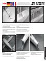
13 14 15
Bild / Fig. 13
- Die Abspannungen von den Flächenstreben zu den
Schwimmern mit Blechschrauben Ø 2,4 x 8 mm an den
oberen Strebenpunkten montieren.
- Attach the rigging connectors to the upper strut points using
2.4 Ø x 8 mm self-tapping screws; the rigging runs from the
wing struts to the floats.
- Montez le haubanage des étais d‘aile vers les ailerons avec
les vis autotaraudeuses Ø 2,4 x 8 mm sur les points supérieurs
des étais.
Bild / Fig. 16
- Übersicht über die Anlenkung der Wasserruder.
- Overall view of the water rudder linkage.
- Vue d‘ensemble de l‘asservissement des gouvernails.
Bilder / Figs. 17 + 18
- Die Gummiringe für die Rückstellung in den Ösen der
Schwimmer bzw. an den Rudern innen einhängen.
- Anlenkseile an den Rudern anbringen.
- Connect the centring rubber bands to the loops on the floats
and the inner holes on the rudders.
- Attach the linkage cables to the rudders.
Figs. 17 +18
- Accrochez les élastiques de rappel dans les oeillets des flot-
teurs et aux gouvernail.
- Installez les filins d‘asservissement aux gouvernails.
Bilder / Figs. 14 + 15
- Die Verspannungen längenmäßig zuordnen und mit
Blechschrauben Ø 2,4 x 8 mm an den Schwimmern ver-
schrauben.
- Assign the rigging according to their length, and fix them to
the floats using 2.4 Ø x 8 mm self-tapping screws.
- Affectez les haubans en onction de leur longueur et vissezles
aux flotteurs avec les vis autotaraudeuses Ø 2,4 x 8 mm.
16
17
18
Ø 2,4 x 8
Ø 2,4 x 8

DE/EN/FR
8
BAU- UND BETRIEBSANLEITUNG SCHWIMMERSET
BUILDING AND OPERATING INSTRUCTIONS FLOAT SET
NOTICE DE MONTAGE ET DE MISE EN OEUVRE DU KIT FLOTTEURS
2019
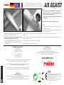
Bild / Fig. 20
- Seitenruder bzw. Spornrad müssen sich in Neutralstellung
befinden.
- Beide Wasserruder in Mittelstellung bringen und Schrauben
der Kupplungen anziehen.
- Neutralstellung und Laufrichtung der Wasserruder prüfen.
Das Modell ist fertig für den ersten Wasserstart.
Bild / Fig. 19
- Anlenkseile über Kreuz zum Spornrad spannen und durch die
Kupplungen des Anlenkhebels schieben.
- Stretch the steering cable and cross them over to align with
the tailwheel tiller steering arm swivel connectors.
- Tendre les filins d‘asservissement vers la béquille en les croi-
sant et glissez-les dans les accouplements du palonnier
d‘asservissement.
Fig. 20
- Ensure that the rudder and tailwheel are at neutral (centre).
- Set both water rudders to centre before tightening the clam-
ping screws in the swivel connectors.
- Check the neutral position and direction of operation of the
water rudders.
The model is now ready for its first take-off from water.
Fig. 20
- La gouverne de direction et la béquille doivent se trouver
parfaitement au neutre.
- Disposer les deux gouvernails en position médiane et serrez les
vis des accouplements.
- Contrôlez la position neutre des gouvernails.
Le modèle est prêt à effectuer son premier décollage de l‘eau.
Modellbau Lindinger GmbH
Industriestraße 10
4565 Inzersdorf im Kremstal
Österreich / Austria / Autriche
Telefon: +43(0)7582/81313-0
Mail: [email protected]
UID Nr.: ATU69266037
„robbe Modellsport“ ist eingetragenes Markenzeichen der Modellbau Lindinger GmbH
Irrtum, Druckfehler und technische Änderungen vorbehalten.
„robbe Modellsport“ is a registered Trademark by Modellbau Lindinger GmbH
Errors, misprints and technical changes reserved.
„robbe Modellsport“ est une marque déposée de Modellbau Lindinger GmbH.
Sous réserve d‘erreurs, de fautes d‘impression et de modications techniques.
Copyright 2019
Modellbau Lindinger 2019
Kopie und Nachdruck, auch auszugsweise, nur mit schriftlicher Genehmigung.
Copy and reprint only with our permission.
Copie et réimpression, même partielle, uniquement avec autorisation écrite.
Service-Adresse
Über Ihren Fachhändler oder:
Contact your Dealer or:
Par l‘intermédiaire de votre revendeur spécialisé ou :
Modellbau Lindinger GmbH, Industriestraße 10, 4565 Inzersdorf im Kremstal
[email protected] +43(0)7582-81313-0
www.robbe.com
Made in China
+14
Produkt ist kein Spielzeug, nur unter unmittelbarer
Aufsicht von Erwachsenen betreiben.
This product is not a toy. Operate only under the
direct supervision of adults.
Ce produit n‘est pas un jouet, à utiliser seulement
sous la surveillance d´un adulte.
-
 1
1
-
 2
2
-
 3
3
-
 4
4
-
 5
5
-
 6
6
-
 7
7
-
 8
8


ROBBE Air Beaver Instruction And User's Manual
- Typ
- Instruction And User's Manual
in anderen Sprachen
- English: ROBBE Air Beaver
- français: ROBBE Air Beaver
Verwandte Artikel
Andere Dokumente
-
 Lindinger 9784998 Benutzerhandbuch
-
MULTIPLEX Schwimmer Satz Funman Bedienungsanleitung
-
-
E-flite EFLA5600 Bedienungsanleitung
-
E-flite EFLA550 Bedienungsanleitung
-
FMS FMM110PF Benutzerhandbuch
-
-
FMS 1220mm Super EZ V4 Bedienungsanleitung
