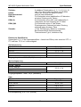
METREL EDMD9035 Benutzerhandbuch
- Kategorie
- Messung
- Typ
- Benutzerhandbuch
Dieses Handbuch eignet sich auch für

METREL MD 9035
Automotive Multimeter Designed to
Work On Real-World Car Signals
MD 9035
User Manual
Bedienungsanleitung
Version 1.0, Code no. 20 751 999

2
Distributor:
METREL d.d.
Ljubljanska cesta 77
1354 Horjul
Slovenia
e-mail: [email protected]
web site: http://www.metrel.si/
Metrel GmbH
Mess und Prüftechnik
Orchideenstrasse 24
90542 Eckental -Brand
Germany
E-mail: [email protected]
Internet: http://www.metrel.de/
Metrel UK
Test & Measurement
Unit 1, Hopton House,
Ripley Drive,
Normanton Industrial Estate,
Normanton,
West Yorkshire
WF6 1QT
Great Britain
E-mail: [email protected]
Internet: http://www.metrel.co.uk/
© 2012 METREL
Mark on your equipment certifies that this equipment meets the requirements of the EC
(European Community) regulations concerning safety and electromagnetic compatibility.
No part of this publication may be reproduced or utilized in any form or by any means
without permission in writing from METREL.

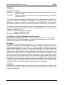
MD 9035 Digital Multimeter Series Table of contents / Inhalt
3
Table of contents/ Inhalt
English
1 Safety ...........................................................................................................................4
2 Cenelec Directives........................................................................................................6
3 Product Description ......................................................................................................7
4 Operation......................................................................................................................9
5 Specifications..............................................................................................................17
6 Maintenance ...............................................................................................................22
Deutsch
1 Sicherheitsbestimmungen ..........................................................................................24
2 Cenelec-Richtlinien.....................................................................................................26
3 Produktbeschreibung..................................................................................................27
4 Betrieb ........................................................................................................................29
5 Spezifikationen ...........................................................................................................37
6 Wartung ......................................................................................................................42

MD 9035 Digital Multimeter Series Safety
4
1 Safety
Terms in this manual
WARNING identifies conditions and actions that could result in serious injury or even
death to the user.
CAUTION identifies conditions and actions that could cause damage or malfunction
in the instrument.
This manual contains information and warnings that must be followed for operating the
instrument safely and maintaining the instrument in a safe operating condition. If the
instrument is used in a manner not specified by the manufacturer, the protection
provided by the instrument may be impaired. The meter is intended only for indoor use.
The meter protection rating, against the users, is double insulation per IEC61010-1 2nd
Ed., EN61010-1 2nd Ed., UL61010-1 2nd Ed. and CAN/CSA C22.2 No. 61010.1-0.92 to
Category II 1000V AC & DC.
Terminals (to COM) measurement category:
V : Category II 1000V AC & DC
A & mAPA : Category II 450V AC & DC
Per IEC61010-1 2nd Ed. (2001) Measurement Category
Measurement Category II (CAT II) is for measurements performed on circuits directly
connected to the low voltage installation. Examples are measurements on household
appliances, portable tools and similar equipment.
WARNING
To reduce the risk of fire or electric shock, do not expose this product to rain or
moisture. To avoid electrical shock hazard, observe the proper safety precautions when
working with voltages above 60 VDC or 30 VAC rms. These voltage levels pose a
potential shock hazard to the user. Do not touch test lead tips or the circuit being tested
while power is applied to the circuit being measured. Keep your fingers behind the
finger guards of the test leads during measurement. Inspect test leads, connectors, and
probes for damaged insulation or exposed metal before using the instrument. If any
defects are found, replace them immediately. Do not measure any current that exceeds
the current rating of the protection fuse. Do not attempt a current measurement to any
circuit where the open circuit voltage is above the protection fuse voltage rating.
Suspected open circuit voltage should be checked with voltage functions. Never attempt
a voltage measurement with the test lead inserted into the PA/mA or A input jack. Only
replace the blown fuse with the proper rating as specified in this manual.
CAUTION
Disconnect the test leads from the test points before changing functions. Always set the
instrument to the highest range and work downward for an unknown value when using
manual ranging mode.

MD 9035 Digital Multimeter Series Safety
5
INTERNATIONAL ELECTRICAL SYMBOLS
Caution ! Refer to the explanation in this Manual
Caution ! Risk of electric shock
Earth (Ground)
Double Insulation or Reinforced insulation
Fuse
AC--Alternating Current
DC--Direct Current

MD 9035 Digital Multimeter Series Cenelec Directives
6
2 Cenelec Directives
The instruments conform to CENELEC Low-voltage directive 2006/95/EC and
Electromagnetic compatibility directive 2004/108/EC

MD 9035 Digital Multimeter Series Product Description
7
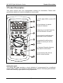
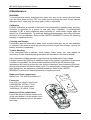
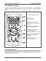
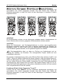
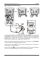
3 Product Description
This user's manual uses only representative model(s) for illustrations. Please refer
specification details for function availability to each model.
1) 3-5/6 digits 6000 counts LCD
display
2) Push-buttons for special
functions & features
3) Selector to turn the Power On
or Off and Select a function
4) Input Jack for milli-amp and
micro-amp current functions
5) Input Jack for all functions
EXCEPT current (PA, mA, A)
functions
6) Common (Ground reference)
Input Jack for all functions
7) Input Jack for 6A (15A for
30sec) current function
Analog bar-graph
The analog bar graph provides a visual indication of measurement like a traditional
analog meter needle. It is excellent in detecting faulty contacts, identifying potentiometer
clicks, and indicating signal spikes during adjustments.

MD 9035 Digital Multimeter Series Product Description
8
Average sensing RMS calibrated
RMS (Root-Mean-Square) is the term used to describe the effective or equivalent DC
value of an AC signal. Most digital multimeters use average sensing RMS calibrated
technique to measure RMS values of AC signals. This technique is to obtain the
average value by rectifying and filtering the AC signal. The average value is then scaled
upward (calibrated) to read the RMS value of a sine wave. In measuring pure sinusoidal
waveform, this technique is fast, accurate and cost effective. In measuring non-
sinusoidal waveforms, however, significant errors can be introduced because of
different scaling factors relating average to RMS values.

MD 9035 Digital Multimeter Series Operation
9
4 Operation
CAUTION
Before and after hazardous voltage measurements, test the voltage function on a
known source such as line voltage to determine proper meter functioning.
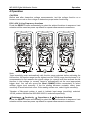
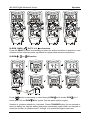
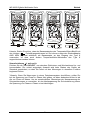
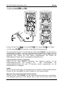
DCV, ACV, & Line Frequency functions
Press the SELECT button momentarily to select the subject functions in sequence. Last
selection will be saved as power up default for repeat measurement convenience.
Note:
*Input sensitivity varies automatically with function range selected before activating the
Hz function. 6V function range has the highest and the 1000V range has the lowest. It is
recommended to first measure the signal voltage (or current) level then activate the Hz
function in that voltage (or current) range to automatically set the most appropriate
trigger level. You can also press the Level (RANGE) button momentarily to select
another trigger level manually. If the Hz reading becomes unstable, select lower
sensitivity to avoid electrical noise. If the reading shows zero, select higher sensitivity.
*Number of Bar-graph pointer is used to indicate input range (sensitivity) selected.
1/2/3/4 pointers indicate that 6/60/600/1000V is selected respectively
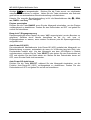
: Resistance, Continuity, Capacitance, & Diode test functions
Press the SELECT button momentarily to select the subject functions in sequence. Last
selection will be saved as power up default for repeat measurement convenience.

MD 9035 Digital Multimeter Series Operation
10
CAUTION
Discharge capacitors before making any measurement. Large value capacitors should
be discharged through an appropriate resistance load.
CAUTION
Using resistance and continuity function in a live circuit will produce false results and
may damage the instrument. In many cases the suspected component must be
disconnected from the circuit to obtain an accurate reading
Continuity function is convenient for checking wiring connections and operation of
switches. A continuous beep tone indicates a complete wire.
Normal forward voltage drop (forward biased) for a good silicon diode is between
0.400V to 0.900V. A reading higher than that indicates a leaky diode (defective). A zero
reading indicates a shorted diode (defective). An OL indicates an open diode
(defective). Reverse the test leads connections (reverse biased) across the diode. The
digital display shows OL if the diode is good. Any other readings indicate the diode is
resistive or shorted (defective).
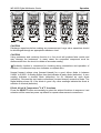
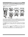
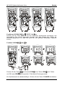
DCmV, ACmV & Temperature oC & oF functions
Press the SELECT button momentarily to select the subject functions in sequence. Last
selection will be saved as power up default for repeat measurement convenience.

MD 9035 Digital Multimeter Series Operation
11
Note: Be sure to insert the banana plug K-type temperature bead probe Bkp60 with
correct polarities. You can also use a plug adapter AMD 9024 (Optional
purchase) with banana pins to K-type socket to adapt other standard K type mini plug
temperature probes.
PA, mA and A Current functions
Press SELECT button momentarily to toggle between DC and AC. Last selection will be
saved as power up default for repeat measurement convenience.
*Note: When measuring a 3-phase system, special attention should be taken to the
phase-to-phase voltage which is significantly higher than the phase-to-earth voltage. To
avoid exceeding the voltage rating of the protection fuse(s) accidentally, always
consider the phase-to-phase voltage as the working voltage for the protection fuse(s).

MD 9035 Digital Multimeter Series Operation
12
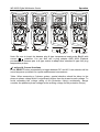
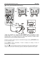
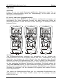
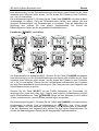
IG-RPM, DWELL , DUTY % & -ms functions
Press the SELECT button momentarily to select the subject functions in sequence. Last
selection will be saved as power up default for repeat measurement convenience.
IG-RPM , or M function
Press button momentarily to select through RPM for 4-stroke, RPM for 2-
stroke and DIS, and RPM M for special 2-stroke waste ignition engine
Number of cylinders defaults at 4 cylinders. Press CYLINDER button for one second or
more to display the cylinder setting and press momentarily again within one second to
select the number of cylinders from 1 through 12 to match the engine under test

MD 9035 Digital Multimeter Series Operation
13
Trigger level defaults at 3. Press the Level (RANGE) button momentarily to select
another trigger level. If the RPM reading becomes unstable, select lower sensitivity to
avoid electrical noise. If the reading shows zero, select higher sensitivity. Number of
Bar-graph pointer is used to indicate sensitivity selected.
DWELL & %Duty functions
Number of cylinders defaults at 4 cylinders. Press Cylinder button for one second or
more to display the cylinder setting, and press momentarily again within one second to
select the number of cylinders from 1 through 12 to match the engine under test. Adjust
the dwell angle according to the procedures outlined in your vehicle service manual. Re-
check the timing whenever the dwell angle has been adjusted.
Press SELECT button momentarily to display DWELL reading in terms of percentage
(%) if required. Positive & negative trigger slopes are selectable through pressing
TRIGGER button for one second or more in %Duty function for advanced
applications.
Trigger level defaults at 3. Press the Level (RANGE) button momentarily to select
another trigger level. If the DWELL or %Duty reading becomes unstable, select
lower sensitivity to avoid electrical noise. If the reading shows zero, select higher
sensitivity. Number of Bar-graph pointer is used to indicate sensitivity selected.

MD 9035 Digital Multimeter Series Operation
14
-ms FUEL INJECTION DETECTOR function
Trigger level defaults at 3. Press the Level (RANGE) button momentarily to select
another trigger level. If the reading becomes unstable, select lower sensitivity to avoid
electrical noise. If the reading shows zero, select higher sensitivity. Number of Bar-
graph pointer is used to indicate sensitivity selected.
Positive & negative trigger slopes are selectable through pressing TRIGGER button
for one second or more.
Press SELECT button momentarily 3 times to display ms reading in terms of
percentage (%) if required
Note: This -ms function applies to both Port Fuel Injectors (PFI) which operate with a
single on time pulse and Throttle Body Injectors (TBI) which operate with twin pulses

MD 9035 Digital Multimeter Series Operation
15
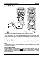
IP-RPM , or M function
Press button momentarily to select through RPM for 4-stroke, RPM for 2-
stroke and DIS, and RPM M for special 2-stroke waste ignition engine
Trigger level defaults at 3. Press the Level (RANGE) button momentarily to select
another trigger level. If the RPM reading becomes unstable, select lower sensitivity to
avoid electrical noise. If the reading shows zero, select higher sensitivity. Number of
Bar-graph pointer is used to indicate sensitivity selected.
Backlighted LCD display
Press the SELECT button for 1 second or more to toggle the LCD backlight. The
backlight will also be turned off automatically after 32 seconds to extend battery life.
Hold
The hold feature freezes the display for later view. Press the HOLD button momentarily
to toggle the hold feature.
Manual or Auto-ranging
Press the RANGE button momentarily to select manual-ranging, and the meter will
remain in the range it was in, the LCD turns off. Press the button momentarily
again to step through the ranges. Press and hold the button for 1 second or more to
resume auto-ranging.

MD 9035 Digital Multimeter Series Operation
16
Note: Manual ranging feature is not available in Hz, , RPM, ms, DWELL & Duty
functions.
Set Beeper Off
Press the RANGE button while turning the meter on to temporarily disable the Beeper
feature. Turn the rotary switch OFF and then back on to resume.
Beep-Jack™ Input Warning
The meter beeps as well as displays “InEr” to warn the user against possible damage to
the meter due to improper connections to the PA, mA, or A input jacks when other
function (like voltage function) is selected.
Auto-Power-Off (APO)
The Auto-Power-Off (APO) mode turns the meter off automatically to extend battery life
after approximately 34 minutes of no rotary switch or push button operations. To wake
up the meter from APO, press the SELECT button momentarily or turn the rotary switch
OFF and then back on. Always turn the rotary switch to the OFF position when the
meter is not in use
Disabling Auto-Power-Off
Press the SELECT button while turning the meter on to temporarily disable the Auto-
Power-Off (APO) feature. Turn the rotary switch OFF and then back on to resume.

MD 9035 Digital Multimeter Series Specifications
17
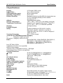
5 Specifications
Display: 3-5/6 digits 6,000 counts
Update Rate: 5 per second nominal
24 Segments Bar graph: 40 per second max
Operating Temperature: 0oC to 40oC
Relative Humidity: Maximum relative humidity 80% for temperature up
to 31oC decreasing linearly to 50% relative
humidity at 40oC
Altitude: Operating below 2000m
Storage Temperature: -20oC ~ 60oC, < 80% R.H. (with battery removed)
Temperature Coefficient: Nominal 0.15 x (specified accuracy)/ oC @ (0oC ~
18oC or 28oC ~ 40oC), or otherwise specified
Sensing: Average sensing
Pollution Degree: 2
Safety: Double insulation per IEC61010-1 2nd Ed.,
EN61010-1 2nd Ed., UL61010-1 2nd Ed. &
CAN/CSA C22.2 No. 61010.1-0.92 to Category II
1000V AC & DC
Transient Protection: 6kV (1.2/50Ps surge)
Terminals (to COM) Measurement Category:
V : Category II 1000V AC & DC
A & mAPA : Category II 450V AC & DC
E.M.C. : Meets EN61326-1:2006 (EN55022, EN61000-3-2,
EN61000-3-3, EN61000-4-2, EN61000-4-3,
EN61000-4-4, , EN61000-4-5, EN61000-4-6,
EN61000-4-8, EN61000-4-11)
In an RF field of 3V/m:
Capacitance function is not specified
Other function ranges:
Total Accuracy = Specified Accuracy + 100 digits
Performance above 3V/m is not specified
Overload Protection:
PA & mA: 0.63A, IR 50kA@500Vac & 1.5kA@450Vdc
A: 6.3A, IR 50kA@500Vac & 1.5kA@450Vdc
V: 1050 Vrms, 1450 Vpeak
mV, Ohm & others: 600 Vrms
Low Battery: Below approx. 2.3V
Power Supply: 1.5V AAA Size battery X 2
Power Consumption (typical): 4.3mA
APO Consumption (typical): 10PA
APO Timing: Idle for 34 minutes
Dimension: 161*80*50mm L*W*H (With Holster)
Weight: Approx. 340 gm (With Holster)
Special Features:
Backlighted LCD
±Trigger: Selectable positive & negative trigger slopes
Cylinder: 9 Selectable number of cylinders (1, 2, 3, 4, 5, 6, 8,
10 & 12) in Dwell and IG-RPM functions
Hold: Freezes the display data for later view

MD 9035 Digital Multimeter Series Specifications
18
Range: Manual & Auto-ranging selection
RPM (4): For RPM of traditional 4-stroke engines which have
1 ignition on every 4 engine strokes
RPM (2): For RPM of DIS & traditional 2-stroke engines
which have 1 ignition on every 2 engine strokes
RPM (2)M: For RPM of 2-stroke waste ignition (on-board)
engines which have 1 ignition on every single
engine stroke
Accessories: Test lead pair; batteries installed; user’s manual;
banana plug type-K thermocouple; Inductive
pickup clip
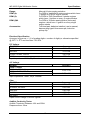
Electrical Specification
Accuracy is given as +/- (% of reading digits + number of digits) or otherwise specified
@ 23oC +/- 5oC and less than 75% R.H.
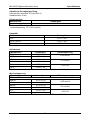
DC Voltage
RANGE Accuracy
60.00mV 0.4%+3d
600.0mV 0.3%+3d
6.000V, 60.00V, 600.0V 0.4%+3d
1000V 0.7%+3d
Input Impedance: 10M:, 50 pF nominal
AC Voltage
RANGE Accuracy
50Hz ~ 500Hz
60.00mV, 600.0mV
6.000V, 60.00V, 600.0V, 2.0% + 5d
1000V 2.2% + 5d
Input Impedance: 10M:, 50 pF nominal
Ohm
RANGE Accuracy
600.0:,0.5%+6d
6.000K:, 60.00K:0.5%+3d
600.0K:0.8%+4d
6.000M:1.0%+5d
60.00M:1.5%+5d
Open Circuit Voltage: 0.45VDC typical
Audible Continuity Tester
Audible Threshold: Between 10: and 200:
Response time: 32ms

MD 9035 Digital Multimeter Series Specifications
19
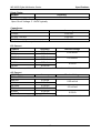
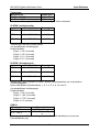
Diode Tester
RANGE Accuracy
1.000V 1.0% + 3d
Test Current: 0.50mA typically
Open Circuit Voltage: < 1.6VDC typically
Capacitance
RANGE Accuracy
6.000PF, 2.0%+5d
60.00PF, 600.0PF3.5%+5d
2000PF4.0%+5d
Accuracies with film capacitor or better
DC Current
RANGE Accuracy Burden Voltage
600.0PA0.7%+3d
6000PA0.5%+3d 0.25 mV/uA
60.00mA 0.7%+3d
600.0mA 0.5%+3d
2.5 mV/mA
6.000A 0.7%+3d
10.00A 1) 0.5%+3d
0.03V/A
1) 6A continuous, >6A to 10A for 30 sec. max with 5 minutes cool down interval
AC Current
RANGE Accuracy Burden Voltage
50HZ~ 500HZ
600.0PA2.2%+5d
6000PA2.0%+5d 0.25 mV/uA
60.00mA 2.2%+5d
600.0mA 2.0%+5d
2.5 mV/mA
6.000A 2.2%+5d
10.00A 1) 1.2%+5d
0.03V/A
1) 6A continuous, >6A to 10A for 30 sec. max with 5 minutes cool down interval

MD 9035 Digital Multimeter Series Specifications
20
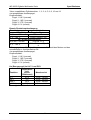
Temperature
RANGE Accuracy
-50 oC ~ 1000 oC 0.5% + 3d
-58 oF ~ 1832 oF 0.5% + 6d
K type thermocouple range & accuracy not included
IP-RPM* (Inductive pickup type)
RANGE Accuracy
RPM 4 240 -20000 RPM 2 RPM
RPM 2 120 -10000 RPM 2 RPM
RPM 2M 60 -5000 RPM 2 RPM
*Measurements via inductive pickup clip
Four selectable trigger levels,
Sensitivity:
Level 1: 3.0V typically
Level 2: 4.5V typically
Level 3: 6.1V typically
Level 4: 8.1V typically
IG-RPM* (Contact signal type)
RANGE Accuracy
RPM 4 60 -20000 RPM 2 RPM
RPM 2 30 -10000 RPM 2 RPM
RPM 2M 15 -5000 RPM 2 RPM
*Measurements via test leads on Dwell, Fuel injection-ms and ignition primary signals
Nine selectable Cylinders: 1, 2, 3, 4, 5, 6, 8, 10 & 12
Four selectable trigger levels,
Sensitivity:
Level 1: 0.8V typically
Level 2: 1.85V typically
Level 3: 3.75V typically
Level 4: 6V typically
DWELL
RANGE Accuracy
0.0o ~ 360.0o * 1.2o /krpm+1d
0.0%~100.0% 0.04%/krpm/cyl+2d
Specified ranges depend on engine rpm and number of Cylinders (cyl)
*Nine selectable Cylinders: 1, 2, 3, 4, 5, 6, 8, 10 & 12
Four selectable trigger levels,
Seite wird geladen ...
Seite wird geladen ...
Seite wird geladen ...
Seite wird geladen ...
Seite wird geladen ...
Seite wird geladen ...
Seite wird geladen ...
Seite wird geladen ...
Seite wird geladen ...
Seite wird geladen ...
Seite wird geladen ...
Seite wird geladen ...
Seite wird geladen ...
Seite wird geladen ...
Seite wird geladen ...
Seite wird geladen ...
Seite wird geladen ...
Seite wird geladen ...
Seite wird geladen ...
Seite wird geladen ...
Seite wird geladen ...
Seite wird geladen ...
Seite wird geladen ...
Seite wird geladen ...
Seite wird geladen ...
Seite wird geladen ...
Seite wird geladen ...
Seite wird geladen ...
-
 1
1
-
 2
2
-
 3
3
-
 4
4
-
 5
5
-
 6
6
-
 7
7
-
 8
8
-
 9
9
-
 10
10
-
 11
11
-
 12
12
-
 13
13
-
 14
14
-
 15
15
-
 16
16
-
 17
17
-
 18
18
-
 19
19
-
 20
20
-
 21
21
-
 22
22
-
 23
23
-
 24
24
-
 25
25
-
 26
26
-
 27
27
-
 28
28
-
 29
29
-
 30
30
-
 31
31
-
 32
32
-
 33
33
-
 34
34
-
 35
35
-
 36
36
-
 37
37
-
 38
38
-
 39
39
-
 40
40
-
 41
41
-
 42
42
-
 43
43
-
 44
44
-
 45
45
-
 46
46
-
 47
47
-
 48
48


METREL EDMD9035 Benutzerhandbuch
- Kategorie
- Messung
- Typ
- Benutzerhandbuch
- Dieses Handbuch eignet sich auch für
in anderen Sprachen
- English: METREL EDMD9035 User manual