ATEN VS0202 Schnellstartanleitung
- Kategorie
- Video-Splitter
- Typ
- Schnellstartanleitung
Dieses Handbuch ist auch geeignet für

Quick Start Guide
Conguration système
• Au moins un moniteur analogique compatible VGA, SVGA, XGA ou Multisync, avec un câble
haute densité de PC standard doté d’un connecteur mâle 15 broches de type HDB.
• Une carte vidéo analogique VGA, SVGA, XGA ou Multisync dotée d’un connecteur femelle
de type HDB 15 broches de PC standard par ordinateur.
• Un câble vidéo avec un connecteur mâle et un connecteur femelle HDB-15 à chaque
extrémité pour chaque ordinateur que vous installez.
Présentation du matériel
Vue avant du VS-0202
Remarque : Le panneau avant du VS-0204 est identique à celui du VS-0202, sauf qu’il
possède deux commutateurs de sélection d’entrée supplémentaires.
Vue arrière du VS-0202
Video Matrix Switch (2 Inputs 2 Outputs)
Quick Start Guide
Video Matrix Switch (2 Inputs 4 Outputs)
Quick Start Guide
© Copyright 2012 ATEN
®
International Co., Ltd.
ATEN and the ATEN logo are trademarks of ATEN International Co., Ltd. All rights reserved. All other
trademarks are the property of their respective owners.
This product is RoHS compliant.
Part No. PAPE-1223-122G Printing Date: 04/2012
Video Matrix Switch (2 Inputs 2 Outputs) User Instructions / Video Matrix Switch (2 Inputs 4 Outputs) User Instructions
System Requirements
• At least one VGA, SVGA, XGA or Multisync compatible analog monitor, with a standard PC
high density cable having a 15 pin HDB type male connector.
• One VGA, SVGA, XGA or Multisync analog video card having a standard PC 15 pin HDB
type female connector per computer.
• A video cable with one male and one female HDB-15 connector at each end for each
computer you will be installing.
Hardware Overview
VS-0202 Front View
Note: The front panel of the VS-0204 is identical to that of the VS-0202, except that it has two
additional Input Select Switches.
VS-0202 Rear View
Note: The rear panel of the VS-0204 is identical to that of the VS-0202, except that it has two
additional Video/Audio OUT ports.
Hardware Installation
Single Stage
B
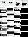
If you will not be cascading the video signal to an additional video splitter, follow the numbered
steps on the diagram to set up the Video Matrix Switch.
Note:
1. Use high density HDB-15 male/female video extender cables to connect the video out ports
on your PCs to the Video IN ports on the Video Matrix Switch.
2. Power on the PCs and monitors only after following the numbered steps on the diagram.
Cascading
To provide video display for more monitors, the video signal can be cascaded down a
maximum of two levels to additional video splitters. Use high density HDB-15 male/female
video extender cables to connect any available Video OUT port on the Video Matrix to the
Video IN port of the video splitter.
Affectation de broches VGA
Remarque : Le panneau arrière du VS-0204 est identique à celui du VS-0202, sauf qu’il
possède deux ports de sortie vidéo/audio supplémentaires.
Installation du matériel
Installation en une étape
B
Si vous ne mettez pas en cascade le signal vidéo vers un répartiteur vidéo supplémentaire,
suivez les étapes numérotées sur le schéma pour congurer Video Matrix.
Remarque :
1. Utilisez des câbles de raccordement vidéo mâle/femelle HDB-15 haute densité pour
connecter les ports de sortie vidéo sur vos PC aux ports d’entrée vidéo sur Video Matrix.
2. Allumez les PC et les moniteurs uniquement après avoir suivi les étapes numérotées sur
le schéma.
Cascade
Pour fournir un affichage vidéo pour plusieurs moniteurs, le signal vidéo peut être mis
en cascade vers le bas sur un maximum de deux niveaux vers les répartiteurs vidéo
supplémentaires. Utilisez des câbles de raccordement vidéo mâle/femelle HDB-15 haute
densité pour connecter les ports de sortie vidéo disponibles sur Video Matrix au port d’entrée
vidéo du répartiteur vidéo.
Spécications
Commutateur vidéo matriciel (2 Ports d’entrée vidéo / audio, 2 Ports de sortie vidéo / audio) manuel d’utilisation / Commutateur vidéo matriciel (2 Ports d’entrée vidéo / audio, 4 Ports de sortie vidéo / audio) manuel d’utilisation
Systemvoraussetzungen
• Mindestens einen VGA-, SVGA-, XGA- oder Multisync-kompatiblen analogen Monitor mit
einem Standard-PC-High-Density-Kabel, das einen 15-poligen HDB-Stecker (Männlein)
besitzt.
• Eine analoge VGA-, SVGA-, XGA- oder Multisync-Grafikkarte mit einer 15-poligen PC-
Standard-Anschlussbuchse (Weiblein) pro Computer.
• Ein Graksignalkabel mit je einem 15-poligen HDB-Stecker Männlein und Weiblein für jeden
Computer, den Sie installieren möchten.
Hardware-Übersicht
Vorderseite des VS-0202
Hinweis: Die Vorderseite des VS-0204 ist identisch mit der des VS-0202, außer, dass dieser
zwei zusätzliche Auswahlschalter für die Eingänge besitzt.
Rückseite des VS-0202
Hinweis: Die Rückseite des VS-0204 ist identisch mit der des VS-0202, außer, dass dieser
zwei zusätzliche Video- und Audioausgänge besitzt.
Hardware installieren
Einzelinstallation
B
Wenn Sie das Graksignal nicht über einen weiteren Grak-Splitter in Reihe schalten, folgen
Sie den nummerierten Schritten im Diagramm, um die Video-Matrix zu installieren.
Hinweis:
1. Verwenden Sie High-Density HDB-15-Grakverlängerungskabel (Männlein/Weiblein), um
den Ausgang der Grakkarte der PCs mit den Eingängen Video IN der Video-Matrix zu
verbinden.
2. Schalten Sie die PCs und Bildschirme nur in der im Diagramm angegebenen Reihenfolge
ein.
Reihenschaltung
Um das Graksignal auf mehreren Monitoren darzustellen, können Sie es auf zwei weitere
Ebenen in Reihe geschalteter Grak-Splitter verteilen. Verwenden Sie ein High-Density HDB-
15-Grakverlängerungskabel (Männlein/Weiblein), um einen beliebigen Ausgang Video OUT
der Video-Matrix mit dem Signaleingang Video IN des Grak-Splitters zu verbinden.
Technische DatenVGA-Stiftzuordnung
Video-Matrix-Switch (2 Video- / Audio-Eingangsports,2 Video- / Audio-Ausgangsports) Bedienungsanleitung / Video-Matrix-Switch (2 Video- / Audio-Eingangsports,4 Video- / Audio-Ausgangsports) Bedienungsanleitung
VS-0202 / 0204
Conmutador/matriz de video (2 puertos de entrada de video/audio) instrucciones para el usuario / Conmutador/matriz de video (4 puertos de entrada de video/audio) instrucciones para el usuario
Requisitos del sistema
• Como Mínimo un monitor analógico VGA, SVGA, XGA o Multisync con cable PC estándar
de alta densidad HDB con 15 patillas (macho).
• Una tarjeta gráfica analógica VGA, SVGA, XGA o Multisync para PC de 15 patillas con
salida HDB hembra en cada ordenador.
• Un cable de video con un conector HDB-15 macho y uno hembra en cada extremo para
cada ordenador que vaya a instalar.
Aspectos generales del hardware
Vista anterior del VS-0202
Nota: el panel frontal del VS-0204 es idéntico al del VS-0202, excepto que éste tiene dos
selectores de entrada adicionales.
Vista posterior del VS-0202
Nota: El panel posterior del VS-0204 es idéntico al del VS-0202, excepto que éste tiene dos
conectores de salida de vídeo/audio adicionales.
Instalación del hardware
Una unidad sola
B
Cuando no vaya a conectar la señal gráca en cascada con un dispersor gráco adicional,
siga los pasos enumerados del diagrama para instalar la matriz gráca.
Nota:
1. Utilice cables de extensión HDB-15 de alta densidad macho/hembra para conectar los
puertos de salida de vídeo de sus PCs a los puertos de entrada Video IN de la matriz
gráca.
2. Encienda los PCs y los monitores sólo después de seguir los pasos exactamente en el
orden indicado en el diagrama.
Cascada
Para mostrar la imagen en varios monitores, puede diversicar la señal gráca en cascada
hasta un máximo de dos niveles de dispersores grácos. Emplee cables de extensión de
vídeo HDB-15 macho/hembra de alta densidad para conectar cualquier puerto de salida de
Video OUT de la matriz gráca a la entrada de vídeo del dispersor gráco.
Especicaciones
Asignación de patillas VGA
# Description Function
1
Display 1 Input
Select Switch
This switch selects the input that will be displayed on the
device connected to output 1. Press the switch to toggle
between the inputs.
• Green LED On indicates display from Input 1
• Orange LED On indicates display from Input 2
2
Display 2 Input
Select Switch
This switch selects the input that will be displayed on the
device connected to output 2. Press the switch to toggle
between the inputs.
• Green LED On indicates display from Input 1
• Orange LED On indicates display from Input 2
3 Source LEDs
Each of these LEDs corresponds to an input port. A lit LED
indicates data transmission from the source connected to its
corresponding input port
4 Power LED Lights to indicate that the unit is receiving power.
# Description Function
1
Video Gain
Switch(VS-0202
only)
Adjust this three position switch to improve video signal
strength. It is especially useful when the monitor cable is
longer than a few meters or when cascading the video signal
to other video splitters.
2 Power Jack The Power Adapter cable plugs in here.
3
Video / Audio IN
Ports
The video and audio cables that connect to the computer’s
video (monitor) and audio (speaker) output ports plug in here.
4
Video / Audio
OUT Ports
The video and audio cables from the monitors and speakers
can plug in to any available port.
# Description Fonction
1
Commutateur de
sélection d’entrée
1 de l’afchage
Ce commutateur sélectionne l’entrée qui s’affiche sur
le périphérique connecté à la sortie 1. Appuyer sur le
commutateur pour passer d’une entrée à une autre.
• Le voyant vert allumé indique l’afchage de l’entrée 1.
• Le voyant orange allumé indique l’afchage de l’entrée 2.
2
Commutateur de
sélection d’entrée
2 de l’afchage
Ce commutateur sélectionne l’entrée qui s’affiche sur
le périphérique connecté à la sortie 2. Appuyer sur le
commutateur pour passer d’une entrée à une autre.
• Le voyant vert allumé indique l’afchage de l’entrée 1.
• Le voyant orange allumé indique l’afchage de l’entrée 2.
3 Voyants source
Chacun de ces voyant correspond à un port d'entrée. Un
voyant allumé indique la transmission des données depuis la
source connectée au port d'entrée correspondant
4
Voyant
d’alimentation
S’allume pour indiquer que l’unité reçoit du courant.
# Description Fonction
1
Commutateur de
gain vidéo
(VS-0202
uniquement)
Réglez ce commutateur à trois positions pour améliorer la
force du signal vidéo. Il est particulièrement utile lorsque
le câble du moniteur est plus long que quelques mètres ou
lors de la mise en cascade du signal vidéo vers les autres
répartiteurs vidéo.
2
Prise jack
d'alimentation
Le câble de l’adaptateur secteur se branche ici.
3
Port s d ’entr é e
vidéo / audio
Les câbles audio et vidéo qui se connectent aux ports de
sortie audio (haut-parleur) et vidéo (moniteur) de l’ordinateur
se branchent ici.
4
Ports de sortie
vidéo / audio
Les câbles vidéo et audio des moniteurs et des haut-parleurs
se branchent sur n’importe quel port disponible.
Modèle VS-0202 VS-0204
Connexion PC - Moniteur 2-2 2-4
Connecteurs
Sortie
2 x HDB 15 broches (femelle)
2 x prises jack audio (femelle)
4 x HDB 15 broches (femelle)
4 x prises jack audio (femelle)
Entrée
2 x HDB 15 broches (mâle)
2 x prises jack audio (femelle)
2 x HDB-15 broches (mâle)
2 x Prises jack audio (femelle)
Alimentation Prise jack CC
Voyants
Alimentation 1
Source 1 1 (vert) 1 (vert)
Source 2 1 (orange) 1 (orange)
Entrée 1 2 (vert) 4 (vert)
Entrée 2 2 (orange) 4 (orange)
Commutateurs à bascule Résolution VGA 2 4
Prise en charge VGA 1920 x 1440 @60Hz
DDC2B Port 1 Port 1 and 3
Commutateur à glissière 1 Ne s’applique pas
Type de signal VGA / SVGA / XGA
Gamme de synchronisation Synchronisation positive/négative
Alimentation électrique DC 5.3V, 2.4A
Consommation électrique CC 5.3V 2.39W CC 5.3V 3.02W
Distance de câble 65 mètres maximum (Video Matrix au moniteur)
Environnement
Température de
fonctionnement
de 0°C à 50°C (HR de 0 à 80 %, sans condensation)
Température de
conservation
de -20°C à 60°C (HR de 0 à 80 %, sans condensation)
Humidité Humidité relative de 0 à 80 %, NC
Propriétés
physiques
Boîtier Métallique
Poids 0.47kg 0.69kg
Dimensions (L x P x H) 13 x 7.7 x 4.5 cm 20 x 7.7 x 4.5 cm
Broche Signal Broche Signal Broche Signal
1
Vidéo
rouge
6
Terre
analogique
11 ID0
2
Vidéo
vert
7
Terre
analogique
12 ID1
3
Vidéo
bleu
8
Terre
analogique
13
Synchro.
horizontale
4 ID2 9 NC 14
Synchro.
verticale
5 Terre 10 Terre 15 ID3
Nr. Beschreibung Funktion
1
Auswahlschalter
Eingang
Bildschirm 1
Mit diesem Schalter wählen Sie den Signaleingang, der
auf dem an Ausgang 1 angeschlossenen Gerät angezeigt
wird. Drücken Sie den Taster mehrmals hintereinander, um
zwischen den verschiedenen Eingängen umzuschalten.
• Die grüne LED bedeutet, dass das an Eingang 1
anliegende Signal angezeigt wird.
• Die orange LED bedeutet, dass das an Eingang 2
anliegende Signal angezeigt wird.
2
Auswahlschalter
Eingang
Bildschirm 2
Mit diesem Schalter wählen Sie den Signaleingang, der
auf dem an Ausgang 2 angeschlossenen Gerät angezeigt
wird. Drücken Sie den Taster mehrmals hintereinander, um
zwischen den verschiedenen Eingängen umzuschalten.
• Die grüne LED bedeutet, dass das an Eingang 1
anliegende Signal angezeigt wird.
• Die orange LED bedeutet, dass das an Eingang 2
anliegende Signal angezeigt wird.
3 Source-LEDs
Jede dieser LED-Anzeigen ist einem Eingangsport
zugeordnet. Leuchtet eine LED, überträgt das an den
betreffenden Port angeschlossene Gerät Daten.
4
LED-
Betriebsanzeige
Leuchtet, wenn das Gerät mit Strom gespeist wird.
Nr. Beschreibung Funktion
1
Signalpegelregler
(nur beim
VS-0202)
Mit diesem Dreistufenschalter stellen Sie die Signalstärke
ein. Er dient dazu, das Signal bei längeren Kabelwegen
oder bei Verwendung mehrerer in Reihe geschalteter Grak-
Splitter anzuheben.
2
Stromeingangs-
buchse
Hier schließen Sie das Stromkabel des Netzteils an.
3
Video- / Audio-
Eingangsports
Hier werden die Video- und Audiokabel zum Computer-
Video- (Monitor) und -audioausgang (Lautsprecher)
angeschlossen.
4
Video- / Audio-
Ausgangsports
Hier werden die Bildschirm- und Lautsprecherkabel
angeschlossen.
Modell VS-0202 VS-0204
Verbindung PC-Monitor 2-2 2-4
Anschlüsse
Aus
2 x HDB-15 (Weiblein)
2 x Audiobuchsen (Weiblein)
4 x HDB-15 (Weiblein)
4 x Audiobuchsen (Weiblein)
Ein
2 x HDB-15 (Männlein)
2 x Audiobuchsen (Weiblein)
2 x HDB-15 (Männlein)
2 x Audiobuchsen (Weiblein)
Stromver-sorgung Stromeingangsbuchse
LED-Anzeigen
Stromversor 1
Source 1 1 (grün) 1 (grün)
Source 2 1 (orange) 1 (orange)
In 1 2 (grün) 4 (grün)
In 2 2 (orange) 4 (orange)
Auswahlschalter 2 4
VGA-Auösung 1920 x 1440 bei 60 Hz
VGA DDC2B-Unterstützung Port 1 Port 1 und 3
Schiebeschalter 1 -
Signaltyp VGA / SVGA / XGA
Synchronisation Positive/Negative Synchronisation
Stromversorgung 5,3 V=, 2,4 A
Stromverbrauch 5,3 V=, 2.39W 5,3 V=, 3.02W
Kabellänge maximal 65 m (Video-Matrix zum Monitor)
Umgebung
Betriebstemperatur 0°-50°C (0 - 80% rel. Luftfeuchte, nicht kondensierend)
Lagertemperatur -20° – 60° C (0 - 80% rel. Luftfeuchte, nicht kondensierend)
Feuchtigkeit 0 - 80 % RL, nicht kondensierend
Physische
Eigenschaften
Gehäuse Metall
Gewicht 0.47kg 0.69kg
Abmessungen (L x B x H) 13 x 7.7 x 4.5 cm 20 x 7.7 x 4.5 cm
Stift Signal Stift Signal Stift Signal
1 Video rot 6 Erde analog 11 ID0
2 Video grün 7 Erde analog 12 ID1
3 Video blau 8 Erde analog 13
Horizontale
Synch.
4 ID2 9 --- 14
Vertikale
Synch.
5 Erde 10 Erde 15 ID3
N° Descripción Función
1
Selector de
entrada de
pantalla 1
Este selector sirve para escoger la entrada cuya señal se
representará en el dispositivo conectado a la salida 1. Pulse
el conmutador para alternar entre las entradas.
• El LED verde indica que se representa la señal de la
entrada 1.
• El LED anaranjado indica que se representa la señal de la
entrada 2.
2
Selector de
entrada de
pantalla 2
Este selector sirve para escoger la entrada cuya señal se
representará en el dispositivo conectado a la salida 2. Pulse
el conmutador para alternar entre las entradas.
• El LED verde indica que se representa la señal de la
entrada 1.
• El LED anaranjado indica que se representa la señal de la
entrada 2.
3 LEDs de origen
Cada uno de estos indicadores LED corresponde a un puerto
de entrada. Si el LED se enciende, se transeren datos del
dispositivo de origen conectado a la entrada correspondiente.
4
Indicador LED de
alimentación
Se ilumina cuando la unidad recibe corriente eléctrica.
N° Descripción Función
1
Selector de
ganancia de
vídeo (sólo para
el VS-0202)
Ajuste este conmutador de tres posiciones para mejorar la
señal gráfica. Ello es especialmente útil cuando el cable
del monitor sea más largo que sólo unos metros o cuando
conecte varios dispersores grácos en cascada.
2
Entrada de
alimentación
Aquí se conecta el cable del adaptador de alimentación.
3
Puertos de
entrada de vídeo/
audio
Aquí se conectan los cables de audio y vídeo procedentes
del puerto de salida de vídeo (monitor) y audio (altavoces)
del ordenador.
4
Puertos de salida
de vídeo/audio
Aquí se conectan los cables de vídeo y audio del monitor y
de los altavoces.
Modelo VS-0202 VS-0204
Conexión PC-monitor 2-2 2-4
Conectores
Salida
2 x HDB-15 (hembra)
2 x clavijas de audio (hembra)
4 x HDB-15 (hembra)
4 x clavijas de audio (hembra)
Entrada
2 x HDB-15 (macho)
2 x clavijas de audio (hembra)
2 x HDB-15 (macho)
2 x clavijas de audio (hembra)
Alimentación Entrada de alimentación
Indicadores
LED
Alimentación 1
Source 1 1 (verde) 1 (verde)
Source 2 1 (anaranjado) 1 (anaranjado)
In 1 2 (verde) 4 (verde)
In 2 2 (anaranjado) 4 (anaranjado)
Conmutadores 2 4
Resolución VGA 1920 x 1440 a 60 Hz
Admite VGA DDC2B Puerto 1 Puerto 1 y 3
Interruptor deslizable 1 -
Tipo de señal VGA / SVGA / XGA
Sincronización Sincronización positiva/negativa
Alimentación c.c. 5,3 V, 2,4 A
Consumo 5,3 V c.c., 2.39W 5,3 V c.c., 3.02W
Longitud de cable máximo 65 metros (de la matriz gráca al monitor)
Entorno
Temperatura
de funcionamiento
0 a 50 °C (0 a 80% HR, sin condensar)
Temperatura
de almacenamiento
-20 a 60 °C (0 a 80% HR, sin condensar)
Humedad 0-80% HR, sin condensar
Propiedades
físicas
Carcasa Metall
Peso 0.47kg 0.69kg
Dimensiones (L x An x Al) 13 x 7.7 x 4.5 cm 20 x 7.7 x 4.5 cm
Patilla Señal Patilla Señal Patilla Señal
1
Vídeo
rojo
6
Tierra
analógica
11 ID0
2
Vídeo
verde
7
Tierra
analógica
12 ID1
3
Vídeo
azul
8
Tierra
analógica
13
Sincr.
horizontal
4 ID2 9 --- 14
Sincr.
vertical
5 Tierra 10 Tierra 15 ID3
Package Contents
1 Video Matrix Switch
1 Power Adapter
1 VGA/Audio Cable(1.8m)
1 User Instructions
The following contains information that relates to China:
Online Registration
International:
http://support.aten.com
North America:
http://www.aten-usa.com/product_registration
Technical Phone Support
International:
886-2-86926959
North America:
1-888-999-ATEN Ext: 4988
United Kingdom:
44-8-4481-58923
All information, documentation, and specications contained in this media are subject to
change without prior notication by the manufacturer. Please visit our website to nd the
most up to date version.
SpecicationsVGA Pin Assignments
Model VS-0202 VS-0204
PC - Monitor Connection 2-2 2-4
Connectors
Out
2 x HDB-15 (female)
2 x 3.5mm
mini stereo jack (female)
4 x HDB-15 (female)
4 x 3.5mm
mini stereo jack (female)
In
2 x HDB-15 (male)
2 x 3.5mm
mini stereo jack (female)
2 x HDB-15 (male)
2 x 3.5mm
mini stereo jack (female)
Power DC Jack
LEDs
Power 1
Source 1 1 (green) 1 (green)
Source 2 1 (orange) 1 (orange)
In 1 2 (green) 4 (green)
In 2 2 (orange) 4 (orange)
Toggle Switches 2 4
VGA Resolution 1920 x 1440 @60Hz
VGA DDC2B Support Port 1 Port 1 and 3
Slide Switch 1 N/A
Signal Type VGA / SVGA / XGA
Sync Range Sync Positive/Negative
Power supply DC 5.3V, 2.4A
Power Consumption DC 5.3V 2.39W DC 5.3V 3.02W
Cable Distance 65 meters maximum (Video Matrix Switch to monitor)
Environment
Operating temperature 0°~50°C (0~80% RH, Non-condensing)
Storage temperature -20°~60°C (0~80% RH, Non-condensing)
Humidity 0-80% RH, NC
Physical Properties
Housing Metal
Weight 0.47kg 0.69kg
Dimensions (Lx W x H) 13 x 7.7 x 4.5 cm 20 x 7.7 x 4.5 cm
Pin Signal Pin Signal Pin Signal
1 Red Video 6 Analog Ground 11 ID0
2 Green Video 7 Analog Ground 12 ID1
3 Blue Video 8 Analog Ground 13 Horizontal Sync
4 ID2 9 NC 14 Vertical Sync
5 Ground 10 Ground 15 ID3
www.aten.com
www.aten.com
www.aten.com
www.aten.com
Front View (VS-0202)
A
Single Stage Installation
B
Rear View (VS-0202)
1 2 3 4
1
2
3 4
1
2
3
4
5
1
2
3
4
Audio cable
Audio cable
Power
adapter cable
Seite laden ...
-
 1
1
-
 2
2


ATEN VS0202 Schnellstartanleitung
- Kategorie
- Video-Splitter
- Typ
- Schnellstartanleitung
- Dieses Handbuch ist auch geeignet für
in anderen Sprachen
- English: ATEN VS0202 Quick start guide
- français: ATEN VS0202 Guide de démarrage rapide
- español: ATEN VS0202 Guía de inicio rápido
- italiano: ATEN VS0202 Guida Rapida
- 日本語: ATEN VS0202 クイックスタートガイド
Verwandte Papiere
-
ATEN VS-0404 Schnellstartanleitung
-
ATEN VE500R Schnellstartanleitung
-
-
ATEN VE200-AT-U Schnellstartanleitung
-
ATEN VS132 Benutzerhandbuch
-
-
-
ATEN VE170 Schnellstartanleitung
-
ATEN Audio/ Schnellstartanleitung
-
ATEN VE300RQ Schnellstartanleitung