
GT 9
Tachogenerator
Montage- und Betriebsanleitung
Mounting and operating instructions
MB023 - 11055627
Baumer_GT9_II_DE-EN (19A1)

Baumer_GT9_II_DE-EN (19A1)
MB023 - 11055627
Inhaltsverzeichnis
Inhaltsverzeichnis
1 Allgemeine Hinweise ................................................................................................................................................ 1
2 Sicherheitshinweise
.................................................................................................................................................3
3 Vorbereitung
..................................................................................................................................................................5
3.1 Lieferumfang
..................................................................................................................................................... 5
3.2 Zur Montage erforderlich (nicht im Lieferumfang enthalten) ...................................................6
3.3 Zur Demontage erforderlich
(nur bei Version mit Konuswelle, nicht im Lieferumfang enthalten) .....................................6
3.4 Erforderliches Werkzeug (nicht im Lieferumfang enthalten) ...................................................6
4 Montage .............................................................................................................................................................................7
4.1 Schritt 1 - Einseitig offene Hohlwelle
................................................................................................... 7
4.2 Schritt 1 - Konuswelle ..................................................................................................................................8
4.3 Schritt 2 - Einseitig offene Hohlwelle ................................................................................................... 9
4.4 Schritt 2 - Konuswelle ..................................................................................................................................9
4.5 Schritt 3 ............................................................................................................................................................ 10
4.6 Schritt 4 ............................................................................................................................................................ 10
4.7 Schritt 5 - Standard .....................................................................................................................................11
4.8 Schritt 5 - Mit Abdeckhaube und Verschraubung .......................................................................11
4.9 Schritt 5 - Mit Abdeckhaube und Kabeltülle .................................................................................. 12
5 Abmessungen ............................................................................................................................................................ 13
5.1 Einseitig offene Hohlwelle
...................................................................................................................... 13
5.1.1 Standard (IP00) und mit Abdeckhaube und Verschraubung (IP44) .............................. 13
5.1.2 Standard (IP00), mit Abdeckhaube und Verschraubung (IP44)
und mit Passfedernut ............................................................................................................................. 13
5.1.3 Mit Abdeckhaube und Kabeltülle (IP44) ....................................................................................... 14
5.2 Konuswelle ...................................................................................................................................................... 14
5.2.1 Standard (IP00) und mit Abdeckhaube und Verschraubung (IP44) .............................. 14
6 Elektrischer Anschluss ....................................................................................................................................... 15
7 Betrieb und Wartung
............................................................................................................................................. 16
7.1 Austausch der Kohlebürsten
................................................................................................................. 16
8 Demontage ....................................................................................................................................................................17
8.1 Schritt 1 - Standard
.....................................................................................................................................17
8.2 Schritt 1 - Mit Abdeckhaube und Verschraubung .......................................................................17
8.3 Schritt 1 - Mit Abdeckhaube und Kabeltülle .................................................................................. 18
8.4 Schritt 2 ............................................................................................................................................................ 18
8.5 Schritt 3 - Einseitig offene Hohlwelle ................................................................................................ 19
8.6 Schritt 4 - Einseitig offene Hohlwelle ................................................................................................ 19
8.7 Schritt 3 - Konuswelle ............................................................................................................................... 19
8.8 Schritt 4 - Konuswelle ............................................................................................................................... 20
8.9 Schritt 5 - Konuswelle ............................................................................................................................... 20
8.10 Schritt 6 - Konuswelle ............................................................................................................................... 20
9 Technische Daten .................................................................................................................................................... 21
9.1 Technische Daten - elektrisch
.............................................................................................................. 21
9.2 Technische Daten - mechanisch ......................................................................................................... 21
9.3 Daten nach Typ ............................................................................................................................................. 22
9.4 Ersatzschaltbild ............................................................................................................................................ 22
10 Zubehör .......................................................................................................................................................................... 25

MB023 - 11055627
Baumer_GT9_II_DE-EN (19A1)
Table of contents
Table of contents
1 General notes ................................................................................................................................................................ 2
2 Security indications
.................................................................................................................................................. 4
3 Scope of delivery
........................................................................................................................................................ 5
3.1 Scope of delivery
............................................................................................................................................ 5
3.2 Required for mounting (not included in scope of delivery) ....................................................... 6
3.3 Required for dismounting
(only for version with cone shaft, not included in scope of delivery) ...................................6
3.4 Required tools (not included in scope of delivery) ........................................................................ 6
4 Mounting ........................................................................................................................................................................... 7
4.1 Step 1 - Blind hollow shaft
......................................................................................................................... 7
4.2 Step 1 - Cone shaft .......................................................................................................................................8
4.3 Step 2 - Blind hollow shaft ......................................................................................................................... 9
4.4 Step 2 - Cone shaft .......................................................................................................................................9
4.5 Step 3 ................................................................................................................................................................ 10
4.6 Step 4 ................................................................................................................................................................ 10
4.7 Step 5 - Standard .........................................................................................................................................11
4.7 Step 5 - With cover and cable gland ..................................................................................................11
4.9 Step 5 - With cover and cable sleeve ............................................................................................... 12
5 Dimensions .................................................................................................................................................................. 13
5.1 Blind hollow shaft
........................................................................................................................................ 13
5.1.1 Standard (IP00) and with cover and cable gland (IP44) ..................................................... 13
5.1.2 Standard (IP00), with cover and cable gland (IP44)
and with key slot ....................................................................................................................................... 13
5.1.3 With cover and cable sleeve (IP44) ................................................................................................ 14
5.2 Cone shaft ....................................................................................................................................................... 14
5.2 .1 Standard (IP00) and with cover and cable gland (IP44) ..................................................... 14
6 Electrical connection ............................................................................................................................................ 15
7 Operation and maintenance
............................................................................................................................. 16
7.1 Replace of the carbon brushes
............................................................................................................ 16
8 Dismounting ................................................................................................................................................................ 17
8.1 Step 1 - Standard
........................................................................................................................................ 17
8.2 Step 1 - With cover and cable gland ................................................................................................. 17
8.3 Step 1 - With cover and cable sleeve ............................................................................................... 18
8.4 Step 2 ................................................................................................................................................................ 18
8.5 Step 3 - Blind hollow shaft ...................................................................................................................... 19
8.6 Step 4 - Blind hollow shaft ...................................................................................................................... 19
8.7 Step 3 - Cone shaft .................................................................................................................................... 19
8.8 Step 4 - Cone shaft .................................................................................................................................... 20
8.9 Step 5 - Cone shaft .................................................................................................................................... 20
8.10 Step 6 - Cone shaft .................................................................................................................................... 20
9 Technical data ............................................................................................................................................................ 23
9.1 Technical data - electrical ratings
....................................................................................................... 23
9.2 Technical data - mechanical design .................................................................................................. 23
9.3 Type data ......................................................................................................................................................... 24
9.4 Replacement switching diagram ......................................................................................................... 24
10 Accessories ................................................................................................................................................................. 25

1
Baumer_GT9_II_DE-EN (19A1)
MB023 - 11055627
1 Allgemeine Hinweise
1 Allgemeine Hinweise
1.1 Zeichenerklärung:
Gefahr
Warnung bei möglichen Gefahren
Hinweis zur Beachtung
Hinweis zur Gewährleistung eines einwandfreien Betriebes des Gerätes
i
Information
Empfehlung für die Gerätehandhabung
1.2 Der Tachogenerator GT 9 ist ein generatorisch arbeitendes Prä zi sions-
Drehzahlmessgerät, das mit Sorgfalt nur von technisch qualiziertem Per sonal gehandhabt
werden darf.
1.3 Lebensdauer der Kohlebürsten unter normalen Bedingungen ≥10
9
Umdrehungen. Ein Wech-
sel der Kohlebürsten ist nur vorsorglich erforderlich.
1.4
Der Lagertemperaturbereich des Gerätes liegt zwischen -15° C bis +70 °C.
1.5
Der Betriebstemperaturbereich des Gerätes liegt zwischen -30 °C bis +130 °C,
am Gehäuse gemessen.
1.6
EU-Konformitätserklärung gemäß den europäischen Richtlinien.
1.7 Wir gewähren 2 Jahre Gewährleistung im Rahmen der Bedingungen des Zentralverbandes der
Elektroindustrie (ZVEI).
1.8 Das Gerät darf nur wie in dieser Anleitung beschrieben geöffnet werden. Reparaturen oder
Wartungsarbeiten, die ein vollständiges Öffnen des Gerätes erfordern, sind ausschließlich vom
Hersteller durchzuführen. Am Gerät dürfen keine Veränderungen vorgenommen werden.
1.9 Bei Rückfragen bzw. Nachlieferungen sind die auf dem Typenschild des Gerätes angege-
benen Daten, insbesondere Typ und Seriennummer, unbedingt anzugeben.
1.10
Entsorgung (Umweltschutz):
Gebrauchte Elektro- und Elektronikgeräte dürfen nicht im Hausmüll entsorgt werden.
Das Produkt enthält wertvolle Rohstoffe, die recycelt werden können. Wenn immer
möglich sollen Altgeräte lokal am entsprechenden Sammeldepot entsorgt werden. Im
Bedarfsfall gibt Baumer den Kunden die Möglichkeit, Baumer-Produkte fachgerecht zu entsor-
gen. Weitere Informationen siehe www.baumer.com.

MB023 - 11055627
Baumer_GT9_II_DE-EN (19A1)
2
General notes 1
1 General notes
1.1 Symbol guide:
Danger
Warnings of possible danger
General information for attention
Informations to ensure correct device operation
i
Information
Recommendation for device handling
1.2 The tachogenerator GT 9 is a generator-based working precision measurement device
which must be handled with care by skilled personnel only.
1.3 Service life of the carbon brushes under normal conditions ≥10
9
revolutions. Replacement of
the carbon brushes is only a recommended precaution.
1.4
The storage temperature range of the device is between -15 °C and +70 °C.
1.5
The operating temperature range of the device is between -30 °C and +130 °C,
measured at the housing.
1.6
EU Declaration of Conformity meeting to the European Directives.
1.7 We grant a 2-year warranty in accordance with the regulations of the ZVEI (Central Association
of the German Electrical Industry).
1.8 The device may be only opened as described in this instruction. Repair or maintenance work
that requires opening the device completely must be carried out by the
manufacturer. Alterations of the device are not permitted.
1.9 In the event of queries or subsequent deliveries, the data on the device type label must be
quoted, especially the type designation and the serial number.
1.10
Disposal (environmental protection):
Do not dispose of electrical and electronic equipment in household waste. The product
contains valuable raw materials for recycling. Whenever possible, waste electrical and
electronic equipment should be disposed locally at the authorized collection point. If
necessary, Baumer gives customers the opportunity to dispose of Baumer products profession-
ally. For further information see www.baumer.com.

3
Baumer_GT9_II_DE-EN (19A1)
MB023 - 11055627
2 Sicherheitshinweise
2 Sicherheitshinweise
2.1 Verletzungsgefahr durch rotierende Wellen
Haare und Kleidungsstücke können von rotierenden Wellen erfasst werden.
• Vor allen Arbeiten alle Betriebsspannungen ausschalten und Maschinen stillsetzen.
2.2 Zerstörungsgefahr durch mechanische Überlastung
Eine starre Befestigung kann zu Überlastung durch Zwangskräfte führen.
• Die Beweglichkeit des Gerätes niemals einschränken.
Unbedingt die Montagehinweise beachten.
• Die vorgegebenen Abstände und/oder Winkel unbedingt einhalten.
2.3 Zerstörungsgefahr durch mechanischen Schock
Starke Erschütterungen, z. B. Hammerschläge, können zur Zerstörung des Gerätes führen.
• Niemals Gewalt anwenden.
Bei sachgemäßer Montage lässt sich alles leichtgängig zusammenfügen.
• Für die Demontage geeignetes Abziehwerkzeug benutzen.
2.4 Zerstörungsgefahr durch Verschmutzung
Schmutz kann im Gerät zu dessen Beschädigung führen.
• Während aller Arbeiten am Gerät auf absolute Sauberkeit achten.
• Niemals Öl oder Fett in das Innere des Gerätes gelangen lassen.
2.5 Zerstörungsgefahr durch klebende Flüssigkeiten
Klebende Flüssigkeiten können die Magnete und Kohlebürsten beschädigen. Die Demontage
eines mit der Achse verklebten Gerätes kann zu dessen Zerstörung führen.
2.6 Explosionsgefahr
Das Gerät nicht in Bereichen mit explosionsgefährdeten bzw. leicht entzündlichen Materialien
verwenden. Durch eventuelle Funkenbildung können diese leicht Feuer fangen und/oder explo-
dieren.

MB023 - 11055627
Baumer_GT9_II_DE-EN (19A1)
4
Securtiy indications 2
2 Security indications
2.1 Risk of injury due to rotating shafts
Hair and clothes may become tangled in rotating shafts.
• Before all work switch off all voltage supplies and ensure machinery is stationary.
2.2 Risk of destruction due to mechanical overload
Rigid mounting may give rise to constraining forces.
• Never restrict the freedom of movement of the device.
The mounting instructions must be followed.
• It is essential that the specied clearances and/or angles are observed.
2.3 Risk of destruction due to mechanical shock
Violent shocks, e. g. due to hammer impacts, can lead to the destruction of the device.
• Never use force.
Mounting is simple when correct procedure is followed.
• Use suitable puller for dismounting.
2.4 Risk of destruction due to contamination
Dirt penetrating inside the device can damage the device.
• Absolute cleanliness must be maintained when carrying out any work on the device.
• Never allow lubricants to penetrate the device.
2.5 Risk of destruction due to adhesive uids
Adhesive uids can damage the magnets and the carbon brushes. Dismounting a device, se-
cured to a shaft by adhesive may lead to the destruction of the device.
2.6 Explosion risk
Do not use the device in areas with explosive and/or highly inammable materials.
They may explode and/or catch re by possible spark formation.

5
Baumer_GT9_II_DE-EN (19A1)
MB023 - 11055627
3 Vorbereitung / Preparation
3 Vorbereitung
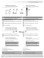
3.1 Lieferumfang
3 Scope of delivery
3.1 Scope of delivery
1
Stator
2
Kohlebürsten (4x),
auch als Zubehör erhältlich, siehe Abschnitt 7.
3
Anschlussklemmen, siehe Abschnitt 6.
4
1)
Anker mit einseitig offener Hohlwelle
4a
1)
Spannelement
4b
1)
Gewindebuchse
5
1)
Anker mit Konuswelle
6
1)
Abdeckhaube
7
1)
Scheibe A4, DIN 137
8
1)
Torxschraube M4x20 mm
9
1)
Kabelverschraubung M12x1,5 mm
10
1)
Kabeltülle HV1218
1)
Je nach Version
1
Stator
2
Carbon brushes (4x),
also available as accessory, see section 7.
3
Connecting terminal, see section 6.
4
1)
Armature with blind hollow shaft
4a
1)
Clamping element
4b
1)
Plug
5
1)
Armature with cone shaft
6
1)
Cover
7
1)
Washer A4, DIN 137
8
1)
Torx screw, M4x20 mm
9
1)
Cable gland M12x1.5 mm
10
1)
Cable sleeve HV1218
1)
Depending on version
1
4
6
9
10
67 8
5
4a 4b
2
3
1)
1)
1)
1)
1) 1)
1) 1) 1) 1) 1) 1)
8 7
Stator und Anker müssen die gleiche
Seriennummer haben. Bei Einsatz
ungleicher Nummern kann ein
Reversierfehler von max. 0,2%
auftreten.
Armature and stator must have the
same serial number. When using
different numbers, a reversing error of
max. 0.2% may occur.

MB023 - 11055627
Baumer_GT9_II_DE-EN (19A1)
6
Vorbereitung / Preparation 3
1211
3.2 Zur Montage erforderlich
(nicht im Lieferumfang enthalten)
3.2 Required for mounting
(not included in scope of delivery)
11
Montagekegel (empfohlen), als Zubehör er-
hältlich: Bestellnummer 11056815
12
2)
Federring A6, DIN 127
13
2)
Befestigungsschraube M6x16 mm, ISO 4762
14
Befestigungsschraube M5x30 mm, ISO 1207
15
Anschlusskabel
11
Mounting cone (recommended), available as
accessory: Order number 11056815
12
2)
Spring washer A6, DIN 127
13
2)
Fixing screw M6x16 mm, ISO 4762
14
Fixing screw M5x30 mm, ISO 1207
15
Connecting cable
13 14
2x
3.3 Zur Demontage erforderlich
(nur bei Version mit Konuswelle,
nicht im Lieferumfang enthalten)
3.3 Required for dismounting
(only for version with cone shaft,
not included in scope of delivery)
16
Gewindestift M6x10 mm, ISO 7436
17
Abdrückschraube M8x45 mm, ISO 4762
16
Grub screw M6x10 mm, ISO 7436
17
Jack screw M8x45 mm, ISO 4762
16
17
15
3.4 Erforderliches Werkzeug
(nicht im Lieferumfang enthalten)
3.4 Required tools
(not included in scope of delivery)
5 mm
2)
und 6 mm
2)
1,6x8,0 mm und 0,8x4 mm
2)
14 mm
4)
, 19 mm
2)
, 22 mm
3)
TX 20
5)
2)
Für Konuswelle
3)
Für einseitig offene Hohlwelle
4)
Für Abdeckhaube und Verschraubung
5)
Für Abdeckhaube
18
Werkzeugset als Zubehör erhältlich:
Bestellnummer 11068265
5 mm
2)
and 6 mm
2)
1.6x8.0 mm and 0.8x4 mm
2)
14 mm
4)
, 19 mm
2)
, 22 mm
3)
TX 20
5)
2)
For cone shaft
3)
For blind hollow shaft
4)
For cover and cable gland
5)
For cover
18
Tool kit available as accessory:
Order number 11068265

7
Baumer_GT9_II_DE-EN (19A1)
MB023 - 11055627
4 Montage / Mounting
4 Montage
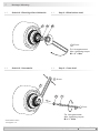
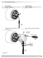
4.1 Schritt 1 - Einseitig offene Hohlwelle
4 Mounting
4.1 Step 1 - Blind hollow shaft
Ansicht V
View V
Ansicht W
View W
Ansicht V
View V
(27)
4
45
ød
h6
ø89
H7
ø74
45°
ød
h6
L2
L1
ød
h6
L1 L2
12 13.6 4
16 18.1 5
Mit Passfedernut
With key slot
Ansicht W
View W
ød
h6
12, 14, 16
2x M5
Die Montage an den Antrieb muss mit
möglichst geringem Winkelfehler und
Parallelversatz erfolgen.
The device must be mounted on the
drive with the least possible angular
error and parallel misalignment.
Die Antriebswelle sollte einen
möglichst kleinen Rundlauffehler
aufweisen. Rundlauffehler verursa-
chen Vibrationen, die die Lebensdauer
des Gerätes verkürzen können.
The drive shaft should have as less
runout as possible.
Runouts can cause vibrations, which
can shorten the service life of the
device.
Antriebswelle einfetten. Lubricate drive shaft.
4
*
* Siehe Seite 5
See page 5
Alle Abmessungen in Millimeter (wenn nicht anders angegeben)
All dimensions in millimeters (unless otherwise stated)

MB023 - 11055627
Baumer_GT9_II_DE-EN (19A1)
8
Montage / Mounting 4
Die Montage an den Antrieb muss mit
möglichst geringem Winkelfehler und
Parallelversatz erfolgen.
The device must be mounted on the
drive with the least possible angular
error and parallel misalignment.
Die Antriebswelle sollte einen
möglichst kleinen Rundlauffehler
aufweisen. Rundlauffehler verursa-
chen Vibrationen, die die Lebensdauer
des Gerätes verkürzen können.
The drive shaft should have as less
runout as possible.
Runouts can cause vibrations, which
can shorten the service life of the
device.
Antriebswelle einfetten. Lubricate drive shaft.
* Siehe Seite 5
See page 5
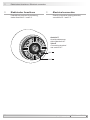
4.2 Schritt 1 - Konuswelle 4.2 Step 1 - Cone shaft
Ansicht X
View X
Ansicht Y
View Y
M6
ø17
ø89
H7
9
20
45°
ø74
2x M5
1:10
Ansicht X
View X
Ansicht Y
View Y
5
*
Alle Abmessungen in Millimeter (wenn nicht anders angegeben)
All dimensions in millimeters (unless otherwise stated)

9
Baumer_GT9_II_DE-EN (19A1)
MB023 - 11055627
4 Montage / Mounting
4.3 Schritt 2 - Einseitig offene Hohlwelle 4.3 Step 2 - Blind hollow shaft
4.4 Schritt 2 - Konuswelle 4.4 Step 2 - Cone shaft
Zul. Anzugsmoment:
Max. tightening torque:
M
t
= 3...4 Nm
Zul. Anzugsmoment:
Max. tightening torque:
M
t
= 3…4 Nm
* Siehe Seite 5 oder 6
See page 5 or 6
1312
**
5
*
4
4a 4b
* * *
22 mm
19 mm
5 mm

MB023 - 11055627
Baumer_GT9_II_DE-EN (19A1)
10
Montage / Mounting 4
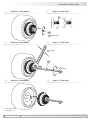
4.5 Schritt 3 4.5 Step 3
Zul. Anzugsmoment:
Max. tightening torque:
M
t
= 3 Nm
4.6 Schritt 4 4.6 Step 4
11
*
1
*
14
*
* Siehe Seite 5 oder 6
See page 5 or 6
1.2x8 mm

11
Baumer_GT9_II_DE-EN (19A1)
MB023 - 11055627
4 Montage / Mounting
4.7 Schritt 5 - Standard 4.7 Step 5 - Standard
4.8 Schritt 5 - Mit Abdeckhaube und Ver-
schraubung
4.7 Step 5 - With cover and cable gland
Ansicht Z
siehe Abschnitt 6.
View Z
see section 6.
Ansicht Z
siehe Abschnitt 6.
View Z
see section 6.
6 7 8
* * *
9
*
15
15
*
*
* Siehe Seite 5 oder 6
See page 5 or 6
*
3
*
3
Zul. Anzugsmoment:
Max. tightening torque:
M
t
= 2...3 Nm
TX 20
14 mm

MB023 - 11055627
Baumer_GT9_II_DE-EN (19A1)
12
Montage / Mounting 4
4.9 Schritt 5 - Mit Abdeckhaube und Ka-
beltülle
4.9 Step 5 - With cover and cable sleeve
* Siehe Seite 5 oder 6
See page 5 or 6
Ansicht Z
siehe Abschnitt 6.
View Z
see section 6.
6 7 8
* * *
10
*
15
*
*
3
Zul. Anzugsmoment:
Max. tightening torque:
M
t
= 2...3 Nm
Keine Silikonkabel verwenden.
Silikonhaltige Atmosphären
können zu erhöhtem Kohlebürstenver-
schleiß führen.
Do not use cable with silicone.
Atmospheres containing silicone can
increase the wearout of the carbon
brushes.
Zur Gewährleistung der angegebenen
Schutzart sind nur geeignete Kabel-
durchmesser zu verwenden.
To ensure the specied protection of
the device the correct cable diameter
must be used.
i
Wir empfehlen, das Gerät so zu
montieren, dass der Kabelanschluss
keinem direkten Wassereintritt
ausgesetzt ist.
i
It is recommended to mount the device
with cable connection facing down-
ward and being not exposed to water.
TX 20

13
Baumer_GT9_II_DE-EN (19A1)
MB023 - 11055627
5 Abmessungen / Dimensions
5.1.2 Standard (IP00), mit Abdeckhaube und
Verschraubung (IP44) und mit Pass-
federnut
(81033, 81108, 81112)
5.1.2 Standard (IP00), with cover and cable
gland (IP44) and with key slot
(81033, 8110 8, 81112)
Drehrichtung positiv
Positive rotating direction
ød
H7
L1 L2
12 13.6 4
16 18.1 5
5 Abmessungen
5.1 Einseitig offene Hohlwelle
5.1.1 Standard (IP00) und mit Abdeckhaube
und Verschraubung (IP44)
(81026, 81053, 81101, 81102 (81031,
81032))
5 Dimensions
5.1 Blind hollow shaft
5.1.1 Standard (IP00) and with cover and
cable gland (IP44)
(81026, 81053, 81101, 81102 (81031,
81032))
Drehrichtung positiv
Positive rotating direction
ød
H7
12
14
16
Alle Abmessungen in Millimeter (wenn nicht anders angegeben)
All dimensions in millimeters (unless otherwise stated)

MB023 - 11055627
Baumer_GT9_II_DE-EN (19A1)
14
Abmessungen / Dimensions 5
5.1.3 Mit Abdeckhaube und Kabeltülle (IP44)
(81111)
5.1.3 With cover and cable sleeve (IP44)
(81111)
Drehrichtung positiv
Positive rotating direction
5.2 Konuswelle
5.2.1 Standard (IP00) und mit Abdeckhaube
und Verschraubung (IP44)
(81251, 81252)
5.2 Cone shaft
5.2 .1 Standard (IP00) and with cover and
cable gland (IP44)
(81251, 81252)
Drehrichtung positiv
Positive rotating direction
Alle Abmessungen in Millimeter (wenn nicht anders angegeben)
All dimensions in millimeters (unless otherwise stated)

15
Baumer_GT9_II_DE-EN (19A1)
MB023 - 11055627
6 Elektrischer Anschluss / Electrical connection
6 Elektrischer Anschluss
Polarität bei positiver Drehrichtung,
siehe Abschnitt 5.1 und 5.2.
6 Electrical connection
Polarity at positive rotating direction,
see section 5.1 and 5.2.
2A1
2A2
Ansicht Z
Anschlussklemmen
siehe Abschnitt 4.7.
View Z
Connecting terminal
see section 4.7.

MB023 - 11055627
Baumer_GT9_II_DE-EN (19A1)
16
7 Betrieb und Wartung
7.1 Austausch der Kohlebürsten
Bei Erreichen der minimalen Kohlebür-
stenlänge von 5,5 mm (L) sollten die
Kohlebürsten ausgewechselt sowie der
Kommutatorraum mit trockener Pressluft
ausgeblasen werden, damit weiterhin ein
einwandfreier Betrieb gewährleistet ist.
7 Operation and maintenance
7.1 Replace of the carbon brushes
When the minimum carbon brush length
of 5.5 mm (L) is reached, the carbon
brushes should be replaced and the com-
mutator area should be cleaned with dry
compressed air in order to ensure perfect
operation.
Betrieb und Wartung / Operation and maintenance 7
2
*
Kohlebürsten, als Zubehör erhältlich
1 Satz (4 Stück, Qualität H87):
Bestellnummer 11076211
2
*
Carbon brushes, available as accessory
1 set (4 pieces, quality H87):
Order number 11076211
2
*
* Siehe Seite 5
See page 5
L

17
Baumer_GT9_II_DE-EN (19A1)
MB023 - 11055627
8 Demontage / Dismounting
8 Demontage
8.1 Schritt 1 - Standard
8 Dismounting
8.1 Step 1 - Standard
8.2 Schritt 1 - Mit Abdeckhaube und Ver-
schraubung
8.2 Step 1 - With cover and cable gland
6 7 8
* * *
9
*
15
15
*
*
* Siehe Seite 5 oder 6
See page 5 or 6
*
3
*
3
TX 20
14 mm
Seite wird geladen ...
Seite wird geladen ...
Seite wird geladen ...
Seite wird geladen ...
Seite wird geladen ...
Seite wird geladen ...
Seite wird geladen ...
Seite wird geladen ...
-
 1
1
-
 2
2
-
 3
3
-
 4
4
-
 5
5
-
 6
6
-
 7
7
-
 8
8
-
 9
9
-
 10
10
-
 11
11
-
 12
12
-
 13
13
-
 14
14
-
 15
15
-
 16
16
-
 17
17
-
 18
18
-
 19
19
-
 20
20
-
 21
21
-
 22
22
-
 23
23
-
 24
24
-
 25
25
-
 26
26
-
 27
27
-
 28
28


Verwandte Artikel
-
Baumer GTB 9 Assembly Instruction
-
-
-
-
-
 Baumer Hübner HOGS 100 S Mounting And Operating Instructions
-
-
-
-
