Kerbl 291130 Electric Slug Fence Starter Kit Benutzerhandbuch
- Typ
- Benutzerhandbuch

(DE) Bedienungsanleitung Elektrischer Schneckenzaun – Starter Set #291130
1. Allgemeines
Der Elektrische Schneckenzaun bildet bei bestimmungsgemäßer Installation eine unüberwindbare Barriere für alle
Arten von Schnecken im heimischen Garten. Durch die niedrige Zaunspannung von 9 V (Blockbatterie) nehmen die
Schnecken keinen Schaden, sondern empfinden lediglich ein unangenehmes Kribbeln und werden sofort zum Um-
drehen bewegt. Für andere Tiere und auch für Menschen ist die Wirkung nicht spürbar und absolut unbedenklich.
2. Bestimmungsgemäße Verwendung
Dieses Produkt sowie dessen Zubehörteile dienen ausschließlich der Vergrämung von Schnecken. Ein anderweitiger Ein-
satz ist nicht vorgesehen. Technische Modifikationen des Systems oder von dessen Bestandteilen sind nicht zulässig!
3. Sicherheitshinweise
• Prüfen Sie das System regelmäßig auf Beschädigungen. Tauschen Sie ggfs. beschädigte Komponenten aus!
• Verstauen Sie lose Kabel, um Stolpern oder anderweitige Verletzungen zu vermeiden!
• Prüfen Sie regelmäßig den Batteriezustand und entsorgen Sie auslaufende oder beschädigte Batterien
umgehend fachgerecht!
• Das Stromgerät darf ausschließlich mit einer 9V Batterie betrieben werden. Der Netzbetrieb ist nicht zulässig.
4. Lieferumfang
Stromgerät mit angeschlossenem
Kontaktclip und Halteplatte
(Art. 291125)
10 m Zaunband
(Art. 291128)
9 V-Batterie Befestigungs-
schraube
5. Optionales Zubehör / Ersatzartikel
Stromgerät mit
angeschlosse-
nem Kontaktclip
und Halteplatte
(Art. 291125)
10 m
Zaunband
(Art. 291128)
20 m
Zaunband
(Art. 291129)
Zaunband-
verbinder
(Art. 291127)
Beetver-
binder
(Art. 291126)
Funktion Stromversorgung Zaunverlän-
gerung und
Reparatur
Zaunverlän-
gerung und
Reparatur
Verbindung
zweier
Zaunbänder
Stromver-
sorgung eines
weiteren un-
abhängigen
Zauns
Abb.
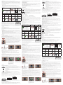
6. Aufbau des Systems (Funktionsprinzip)
Das Zaunband verfügt über zwei parallele verlaufende, elektrisch leitfähige
Kontaktbänder. Eines der Kontaktbänder wird im Betrieb in regelmäßigen
Abständen (ca. 2 Sekunden) für kurze Zeit (wenige Millisekunden) unter 9V
Spannung versetzt.
Durch die schleimige, feuchte Oberfläche der Schnecke ist diese besonders
elektrisch leitfähig. Stellt die Schnecke nun bei dem Versuch das Zaunband zu
überqueren eine Verbindung zwischen beiden Kontaktbändern her, so fließt
kurzzeitig ein geringer Strom. Die Schnecke nimmt dadurch keinerlei Schaden,
empfindet den Stromfluss aber als unangenehm und ändert ihre Richtung.
Für Menschen und andere Tiere sind Strom und Spannung der Batterie zur Wahrnehmung viel zu gering.
Der Betrieb ist damit absolut unbedenklich.
Es ist möglich bis zu drei separate Zaunabschnitte mit nur einem Stromgerät zu versorgen (siehe Kapitel 9. Betrieb
mehrerer Zäune mit einem Stromgerät).
7. Installation
7.1. Vorbereitungen vor der Installation
Umgebungsbedingungen
Halten Sie nach Möglichkeit ausreichend Abstand zum Erdboden ein, um eine Verschmutzung des Zauns oder den
Bewuchs durch Pflanzen zu vermeiden. Bei Hochbeeten empfiehlt sich die Montage im oberen Drittel. Achten Sie stets
darauf, dass Pflanzen nicht in Kontakt mit dem Zaunband kommen. Dies kann die Funktion negativ beeinflussen.
Oberfläche:
Vor der Installation des Zaunbands sollten folgende Punkte beachtet werden, um eine maximale Haftung des
Zaunbands zu gewährleisten:
• Untergrund möglichst staub- und schmutzfrei: Untergrund gegebenenfalls vor der Installation reinigen und gut
abtrocknen lassen.
• Untergrund frei von Fetten und Ölen: Mögliche Verunreinigung des Untergrunds mit fettlösender Substanz reinigen.
Besonders metallische Oberflächen sind häufig geölt oder gefettet!
• Achtung: Auf frisch ölbehandelten Hölzern kann die Haftung des Zaunbands beeinträchtigt werden. Warten Sie
einige Wochen mit der Montage des Zaunbands bis das Öl weitgehend eingezogen ist.
• Holz: Die Oberfläche sollte möglichst glatt sein (gehobelt oder geschliffen). Eine ölfreie, wasserfeste Beschichtung
für den Außenbereich wird empfohlen um die Anhaftung des Zaunbands zu erhöhen.
• Beton: Die Oberfläche sollte zunächst gereinigt und abgescheibt werden, um grobe Körner und Unebenheiten zu
beseitigen. Eine Vorbehandlung der Oberfläche mit Tiefengrund wird empfohlen um die Anhaftung des Zaunbands
zu gewährleisten.
Zaunanschluss:
Vor dem Anbringen des Zaunbandes müssen die Positionen der Halteplatten des Stromgeräts und eventueller Beetver-
binder ausgewählt werden (die Montage der Halteplatte erfolgt zeitgleich mit dem Ankleben des Zaunbandes)
7.2. Installation des Zaunbandes
Aufkleben des Zaunbandes und Anbringen der Halteplatten
Beachten Sie, dass das Zaunband niemals liegend sondern ausschließlich an vertikalen Flächen angebracht werden
darf. Anderenfalls kann Regenwasser nicht abfließen und so einen Kurzschluss verursachen. Das selbstklebende
Zaunband lässt sich auf beinahe allen Arten von Untergründen (Holz, Metall, Kunststoff, Stein und Beton) einfach und
dauerhaft befestigen und kann bei Bedarf mit einer Haushaltsschere gekürzt werden.
Ziehen Sie die Schutzfolie an der rückseitigen Klebefläche des Zaunbands stückweise ab.
Kleben Sie das Zaunband möglichst geradlinig auf den vorgesehenen Untergrund. Kleine
Spalten am Untergrund (kleiner 2-3mm) sind unproblematisch. Sind diese größer, so können
kleine Schnecken hindurchkriechen! Verschließen Sie eventuelle Lücken oder legen Sie das
Zaunband an die Kontur an.
Platzieren Sie jeweils die Halteplatte des Stromgeräts oder des Beetverbinders (falls mehrere
Zäune mit einem Gerät betrieben werden sollen, siehe auch unter 10. „Betrieb mehrerer Zäune
mit einem Stromgerät“) bevor Sie das Zaunband fest mit der Handfläche andrücken.
Bei Holzuntergründen kann die Halteplatte auch vor dem Anbringen des Zaunbandes mit
Schrauben befestigt werden. Auf allen anderen Untergründen wird die Halteplatte nur mit der
Klebekraft des Zaunbandes befestigt.
Sollte das Zaunband zu lang sein, können Sie es mithilfe einer Schere kürzen.
Achten Sie darauf, dass die Enden möglichst gerade sind.
Zaunband verlängern
Bei Bedarf kann das Zaunband mittels 10m Zaunband (Art. 291128) oder 20m Zaunband (Art. 291129) und Zaunband-
verbinder (Art. 291127) verlängert werden. Diese Artikel sind nicht im Lieferumfang enthalten und als Zubehör erhältlich.
Gehen Sie dazu wie folgt vor:
1 Stromgerät
2 Test-Button
3 LED Batteriezustand
4 LED Zaunzustand
5 Kabel
6 Kontaktclip
7 Halteplatte
14
3
2
6
7
5
1. Schneiden Sie beide Enden des
Zaunbandes möglichst gerade ab,
sodass diese bündig zusammen-
treffen (kein Überlappen!)
2. Platzieren Sie hinter beiden
Bandenden mittig die Halteplatte.
Ziehen Sie den Schutzfilm der
Bänder ab und drücken Sie diese
fest an. Die Zaunbänder dürfen
nicht überlappen.
3. Platzieren Sie den Kontaktclip
zur Herstellung der elektrischen
Brücke.
TIPP: Wenn Sie eine beliebige Stelle des Zauns auf Funktion prüfen möchten, gehen Sie dazu wie folgt vor:
Überbrücken Sie mit einem metallischen Gegenstand (z.B. Nagel, Schraubendreher o.ä.) für mindestens
10 Sekunden beide Kontaktstreifen des Zaunbands an der Stelle, die Sie überprüfen möchten.
Prüfen Sie zeitgleich das Stromgerät:
a. Beginnt die Zaunzustand LED nach 10 Sekunden rot zu blinken, so ist die Funktion des Zauns an dieser
Stelle in Ordnung.
b. Kommt kein Hinweis auf (oder blinkt die Zaunzustand LED grün bei Drücken des Testbuttons) so besteht
keine durchgängige elektrische Verbindung am Zaun. Überprüfen Sie alle Kontaktstellen und führen Sie
den Test erneut durch.
Der gesamte Zaun muss keine Schleife bilden, ein Verbinden der offenen Enden ist also nicht notwendig, erhöht
jedoch die Zuverlässigkeit. Überschüssiges Zaunband kann einfach mit einer Haushaltsschere abgeschnitten werden.
Praxistipp: Sie können mit dem Elektrischen Schneckenzaun aus diesem Grund auch Rasenkanten vor Schnecken
schützen ohne eine Schleife mit dem Zaunband zu bilden.
Achten Sie darauf, dass die abgeschnittenen Enden keinen Kurzschluss verursachen. Dies ist vor allem bei
metallischen Untergründen relevant. Entfernen Sie dazu an den Enden einfach jeweils ein Stück der beiden leitenden
Aluminiumbänder vom Trägermaterial (ca. 2mm)
7.3. Anschließen des Stromgeräts
Verbinden Sie den Kontaktclip des
Stromgeräts mit der Halteplatte.
Befestigen Sie das Stromgerät
mithilfe der beiliegenden Schraube
stets hängend (Aufhängungs-
öffnung an der Rückseite) um die
Dichtheit zu gewährleisten.
Tipp: Wenn Sie keine Möglichkeit
haben das Gerät am Beet zu
befestigen, können Sie das
Gerät hilfsweise an einer in den
Boden eingeschlagenen Holzlatte
befestigen.
Drücken Sie den Test-Button um
die Funktion des Zauns zu prüfen.
Bei ordnungsgemäßer Installation
blinkt die Hinweis LED Zaunzustand
grün (siehe Kapitel 8. Bedienung).
8. Bedienung
8.1. Einschalten des Stromgeräts
Mit dem Einsetzen der Batterie wird das Gerät automatisch aktiviert und direkt betriebsbereit.
8.2. Zaunzustand
• Bei ordnungsgemäßer Installation des Zaunbandes blinkt die Hinweis LED grün.
• Im Falle einer Störung (Kurzschluss) blinkt die Hinweis LED rot. In diesem Fall besteht an einer
Stelle am Zaun eine direkte elektrische Verbindung zwischen den beiden Kontaktbändern (z.B.
durch metallischen Kontaktschluss, unsachgemäße Verlängerung, starken Bewuchs des Zauns
o.ä.). Überprüfen Sie den gesamten Zaun und beheben Sie den Kurzschluss.
CHECK
8.3. Batteriezustand
• Bei ausreichender Batteriespannung blinkt die Hinweis LED grün bei Drücken des Test-Buttons.
• Bei niedriger Batteriespannung blinkt die Hinweis LED bei Drücken des Test-Buttons rot.
Bei leerer Batterie leuchtet die Hinweis LED permanent rot. Ersetzen Sie in beiden Fällen
umgehend die Batterie.
8.4. Testbutton
• Um Energie zu sparen, blinken die Hinweis LEDs nur im Störungsfall permanent
(Zaunstörung, Batterie leer).
• Durch Drücken des Testbuttons können Zustand von Zaun und Batterie aber jederzeit
überprüft werden.
9. Betrieb mehrerer Zäune mit einem Stromgerät
Bei Bedarf können mehrere separate Zäune mit einem Beetverbinder (Art. 291126) verbunden und somit mit einem
einzigen Stromgerät betrieben werden.
Dies bietet sich beispielsweise dann an, wenn separate, nebeneinanderstehende Beete umzäunt werden sollen.
Das Stromgerät wird an einem Beet angeschlossen. Ein weiteres Beet wird mithilfe des Beetverbinders (Art. 291126)
verbunden und mit Strom versorgt.
Der Beetverbinder besteht aus zwei mit einem Kabel verbundenen Kontaktclips und zwei Halteplatten. Die Montage
der Halteplatten sowie der Kontaktclips wird in Kapitel 7.2 und 7.3 beschrieben.
Anschluss von weiteren Beeten:
Beetverbinder (Art. 291126)
Beetverbinder (Art. 291126)
Bitte beachten Sie immer die maximal zulässige Zaunlänge von 30m. Darüber hinaus kann die Wirkung des Zauns nach-
lassen, die Batterielebensdauer kann sich erheblich verkürzen.
10. Reinigung und Instandhaltung
10.1. Entfernen von Schneckenschleim
Bei starkem Schneckenbefall kann sich Schleim auf dem Zaunband ablagern. Dieser kann die Funktion des Zauns
beeinflussen und wirkt sich in hoher Konzentration negativ auf die Batterielebensdauer aus. Entfernen Sie den
aufgeweichten Schleim nur bei nasser Witterung mit einem nassen Schwamm oder Lappen. Niemals angetrockneten
Schleim abkratzen, da dadurch der metallische Leiter des Zaunbands beschädigt werden kann.
10.2. Entfernen von Bewuchs
Bewuchs (Gräser, Blätter…) kann elektrische Brücken bilden und die Funktion negativ beeinflussen. Außerdem
können Pflanzenteile von den Schnecken als „Leiter“ genutzt werden, um den Zaun zu überwinden. Schneiden Sie
etwaigen Bewuchs daher regelmäßig zurück.
11. Wartung und Reparatur
11.1. Austausch der Batterie
Bei niedrigem Batteriestand muss die 9V Blockbatterie getauscht werden. Achten Sie beim Tausch der Batterie darauf,
dass der Deckel wieder korrekt platziert und angeschraubt wird, um die Dichtheit des Gehäuses zu gewährleisten.
12. Fehler und mögliche Lösungen
12.1. Teile des Zauns oder der gesamte Zaun werden von Schnecken überwunden
Überprüfen Sie alle Kontaktstellen auf Durchgängigkeit. Führen Sie den unter 7.2 beschrieben Test durch, um die
fehlerhafte Stelle zu lokalisieren.
12.2. Die Zaunhinweis LED blinkt permanent rot
Es liegt ein Kurzschluss am Zaunband vor (beide Kontaktstreifen wurden überbrückt, beispielsweise durch einen
metallischen Fremdkörper oder durch unsachgemäße Installation der Komponenten). Prüfen Sie die Installation um
den Kurzschluss zu beheben.
13. Technische Daten
• Betriebsspannung: 9V
• Batterielaufzeit: ca. 6 Monate (bei 10m Zaunlänge, ohne Bewuchs)
14. Entsorgung
Elektroschrott
Die sachgerechte Entsorgung des Gerätes nach dessen Funktionstüchtigkeit obliegt dem Betreiber.
Beachten Sie die einschlägigen Vorschriften Ihres Landes. Das Gerät darf nicht mit dem Hausmüll
entsorgt werden. Im Rahmen der EU-Richtlinie über die Entsorgung
von Elektro- und Elektronik-
Altgeräten wird das Geraät bei den kommunalen Sammelstellen bzw. Wertstoffhöfen kostenlos
entgegengenommen oder kann zu Fachhändlern, die einen Rücknahmeservice anbieten, zurück-
gebracht werden. Die ordnungsgemäße Entsorgung dient dem Umweltschutz und verhindert
mögliche schädliche Auswirkungen auf Mensch und Umwelt.
CE-Konformitätserklärung
Hiermit erklärt die Albert KERBL GmbH, dass sich das in dieser Anleitung beschriebene Produkt/
Gerät in Übereinstimmung mit den grundlegenden Anforderungen und den übrigen einschlägigen
Bestimmungen und Richtlinien befindet. Das CE-Zeichen steht für die Erfüllung der Richtlinien
der Europäischen Union.
Expertenteam Hobbyfarming
(FR) Mode d’emploi Clôture électrique anti-limaces – Kit débutant #291130
1. Généralités
Une fois installée de manière conforme à l’usage prévu, la clôture électrique anti-limaces constitue une barrière
infranchissable pour toutes sortes de limaces dans le jardin familial. Grâce à la faible tension de la clôture de 9volts
(pile monobloc), les limaces ne subissent aucun dommage et ne ressentent que des picotements désagréables qui les
incitent immédiatement à faire demi-tour. L’effet est imperceptible et absolument inoffensif pour les autres animaux
et pour l’homme.
2. Utilisation conforme à l’usage prévu
Ce produit et ses accessoires servent exclusivement à repousser les limaces. Aucune autre utilisation n’est prévue
pour ce produit. Il est interdit de procéder à des modifications techniques du système ou de ses parties constituantes!
3. Consignes de sécurité
• Vérifiez l’absence d’endommagement du système régulièrement. Remplacez les composants endommagés si
nécessaire!
• Attachez les câbles détachés afin d’éviter de trébucher et de vous blesser!
• Vérifiez régulièrement l’état de la pile et éliminez immédiatement les piles qui fuient ou qui sont endommagées
de manière appropriée!
• L’utilisation de l’électrificateur est exclusivement permise avec une pile 9volts. Une utilisation sur secteur est
interdite.
4. Pièces fournies
Électrificateur avec clip de contact
raccordé et plaque de maintien (Réf.
291125)
Ruban de clôture
de 10 m
(Réf. 291128)
Pile
monobloc
de 9volts
Vis de fixation
5. Accessoires en option / pièces de rechange
Électrificateur
avec clip de
contact raccordé
et plaque de
maintien (Réf.
291125)
10m
Ruban de
clôture
(Réf.
291128)
20m
Ruban de
clôture
(Réf.
291129)
Connecteur
pour ruban
de clôture
(Réf.
291127)
Connecteur
de plates-
bandes
(Réf.
291126)
Fonction Alimentation
électrique
Rallonge de
clôture et
réparation
Rallonge de
clôture et
réparation
Connexion
entre deux
rubans de
clôture
Alimentation
électrique
d’une autre
clôture indé-
pendante
Fig.
6. Structure du système (principe de fonctionnement)
Le ruban de clôture dispose de deux bandes de contact parallèles et conduc-
trices d’électricité. Pendant le fonctionnement, l’une des bandes de contact est
soumise à intervalles réguliers (environ 2 secondes) à une tension de 9volts
pendant un très bref laps de temps (quelques millisecondes).
L’humeur visqueuse et humide rend la limace particulièrement conductrice
d’électricité. Un faible courant électrique circule brièvement dès que la limace
établit une connexion entre les deux bandes de contact en tentant de franchir le
ruban de clôture. La limace ne subit alors aucun dommage, mais elle ressent le
flux de courant comme désagréable et change de direction.
Le courant et la tension de la pile sont bien trop faibles pour être perçus par l’homme et d’autres animaux.
Le fonctionnement est donc absolument inoffensif.
Un seul électrificateur permet d’alimenter jusqu’à trois sections de clôture distinctes (voir chapitre 9. Utilisation de
plusieurs clôtures avec un électrificateur).
7. Installation
7.1. Préparation de l’installation
Conditions ambiantes
Si possible, respectez une distance susante par rapport à la terre pour éviter que la clôture ne se salisse ou qu’elle
ne soit couverte par la végétation. Pour les parterres surélevés, nous recommandons de l’installer dans le tiers
supérieur. Veillez toujours à ce que les plantes n’entrent pas en contact avec le ruban de clôture. Un contact avec les
plantes risque d’avoir une influence négative sur la clôture.
Surface:
Avant de procéder à l’installation du ruban de clôture, observer les points suivants afin de garantir une adhérence
maximale du ruban de clôture:
• Support exempt de poussières et de saletés dans la mesure du possible: Si nécessaire, nettoyer le support avant
l’installation et laisser-le bien sécher.
• Support exempt de graisses et d’huile: Nettoyer les éventuelles salissures du support avec une substance dégrais-
sante. Notamment les surfaces métalliques sont fréquemment huilées ou graissées!
• Attention: Il se pourrait que l’adhérence du ruban de clôture soit entravée sur les bois fraîchement traités.
Patientez quelques semaines jusqu’à ce que l’huile soit largement absorbée, avant de procéder à l’installation du
ruban de clôture.
• Bois : La surface doit être aussi lisse que possible (rabotée ou poncée). Un revêtement sans huile et imperméable
est recommandé à l’extérieur pour augmenter l’adhérence du ruban de clôture.
• Béton : La surface doit être préalablement nettoyée et abrasée afin d'éliminer les gros grains et les irrégularités. Un
traitement préliminaire de la surface avec un primaire d'accrochage est recommandé pour garantir une meilleure
adhérence du ruban de clôture.
Raccordement de la clôture:
Avant de poser le ruban de clôture, il faut choisir les positions des plaques de maintien de l’électrificateur et des
éventuels connecteurs de plate-bande (la pose de la plaque de maintien se fait en même temps que le collage du
ruban de clôture).
7.2. Installation du ruban de clôture
Collage du ruban de clôture et mise en place des plaques de maintien
Veuillez considérer que le ruban de clôture ne doit jamais être posé à plat, mais exclusivement sur des surfaces
verticales. Au cas contraire, l’eau de pluie ne pourrait pas s’écouler et provoquer un court-circuit. Le ruban de clôture
autocollant se fixe facilement et durablement sur presque tous les types de supports (bois, métal, plastique, pierre et
béton) et peut être raccourci avec des ciseaux de ménage si nécessaire.
Retirez la pellicule de protection au dos de la surface adhésive du ruban de clôture progressi-
vement. Collez le ruban de clôture en ligne aussi droite que possible sur le support prévu. Les
petits espaces libres sur le support (de moins de 2à3mm) ne posent pas de problème. S’ils
sont plus larges, les petites limaces pourraient s’y glisser et franchir le ruban! Bouchez les
éventuels espaces libres ou posez le ruban de clôture sur le contour.
Placez la plaque de maintien de l’électrificateur ou du connecteur de plate-bande (si plusieurs
clôtures doivent être utilisées avec un seul électrificateur, voir également le point 10:
«Utilisation de plusieurs clôtures avec un électrificateur») avant de presser le ruban de clôture
fermement avec la paume de la main sur le support.
Sur les supports en bois, la plaque de maintien peut également être fixée avec des vis avant la
pose du ruban de clôture. Sur tous les autres supports, la plaque de maintien est uniquement
fixée par la pégosité du ruban de clôture.
Si le ruban de clôture est trop long, vous pouvez le raccourcir avec des ciseaux.
Veillez à ce que les extrémités soient aussi droites que possible.
Rallongement du ruban de clôture
Si nécessaire, vous pouvez rallonger le ruban de clôture avec le ruban de clôture de 10mètres (Réf. 291128) ou le
ruban de 20mètres (Réf. 291129) et des connecteurs de ruban (Réf. 291127).
Ces articles ne sont pas fournis et disponibles comme accessoires.
Procédez comme suit:
1 Électrificateur
2 Bouton de test
3 LED d’état de la pile
4 LED d’état de la clôture
5 Câble
6 Clip de contact
7 Plaque de maintien
14
3
2
6
7
5
1. Coupez les deux extrémités
du ruban de clôture à angle
aussi droit que possible, de sorte
qu’elles puissent s’aeurer (sans
chevauchement!).
2. Placez la plaque de maintien au
milieu derrière les deux extrémités
du ruban. Retirez la pellicule de
protection des rubans et pressez-les
fermement sur le support. Les
rubans de clôture ne doivent pas
se chevaucher.
3. Mettez le clip de contact
en place pour réaliser le pont
électrique.
ASTUCE: Procédez comme suit si vous voulez vérifiez le fonctionnement de n’importe quel endroit de la clôture:
Servez-vous d’un objet métallique (un clou, un tournevis ou un objet similaire) pour ponter les deux bandes de
contact du ruban de clôture à l’endroit que vous voulez contrôler pendant au moins 10 secondes.
Vérifiez simultanément le fonctionnement de l’électrificateur:
a. L’endroit de la clôture à contrôler fonctionne correctement si la LED d’état de la clôture commence à clignoter en
rouge après 10secondes.
b. Aucune connexion électrique n’est établie à défaut d’un signal quelconque (ou si la LED d’état de la clôture ne
clignote pas en vert en appuyant sur le bouton de test). Vérifiez tous les points de contact et répétez le test.
La clôture dans l’ensemble ne former une boucle, et il n’est donc pas requis de relier les extrémités ouvertes, bien
que cela puisse augmenter la fiabilité de fonctionnement. Vous pouvez couper les excédents du ruban de clôture avec
des ciseaux de ménage.
Conseil pratique: Pour cette raison, vous pouvez également utiliser la clôture électrique anti-limaces pour protéger
les bordures de pelouse contre les limaces sans former de boucle avec le ruban de clôture.
Veillez à ce que les extrémités coupées ne provoquent pas de court-circuit. Cette précaution est particulièrement
importante pour les supports métalliques. Pour ce faire, retirez simplement un morceau (d’environ 2mm) de chacun
des deux rubans en aluminium conducteurs du matériau support.
7.3. Raccordement de l’électrificateur
Raccordez le clip de contact de
l’électrificateur avec la plaque
de maintien.
Fixer toujours l’électrificateur en
suspension à l’aide de la vis fournie
(trou de suspension à l’arrière) afin
de garantir l’étanchéité.
Conseil pratique: Si vous n’avez
pas la possibilité de fixer l’appareil
à la plate-bande, vous pouvez le
fixer à une latte en bois enfoncée
dans le sol.
Appuyez sur le bouton de test pour
vérifier le fonctionnement de la
clôture. Si l’installation est correcte,
la LED de signalisation clignote en
vert (voir chapitre8. Utilisation).
8. Utilisation
8.1. Connexion de l’électrificateur
L’électrificateur est activé automatiquement dès l’insertion de la pile et prêt à fonctionner.
8.2. État de la clôture
• Si le ruban de clôture est correctement installé, la LED de signalisation clignote en vert.
• La LED de signalisation clignote en rouge lors d’un dérangement (court-circuit). Dans ce cas, la
clôture est soumise à une connexion électrique directe entre les deux bandes de contact (cela
peut provenir d’un contact métallique, d’une rallonge incorrecte, d’une forte végétation sur la
clôture ou autre). Contrôlez l’ensemble de la clôture et remédiez au court-circuit.
CHECK
8.3. État de la pile
• Si la tension de la pile est susante, la LED de signalisation clignote en vert dès l’actionne-
ment du bouton de test.
• Si la tension de la pile est trop faible, la LED de signalisation clignote en rouge dès l’actionne-
ment du bouton de test rouge.
Si la pile est vide, la LED de signalisation brille en rouge en permanence. Remplacer immédia-
tement la pile dans ces deux cas.
8.4. Bouton de test
• Pour économiser de l’énergie, les LED de signalisation clignotent uniquement en cas de
dérangement (panne de la clôture, pile vide).
• L’actionnement du bouton de test permet de vérifier l’état de la clôture et de la pile à
tout moment.
9. Utilisation de plusieurs clôtures avec un électrificateur
Si nécessaire, vous pouvez relier plusieurs clôtures séparées avec un connecteur de plate-bande (Réf. 291126) et les
faire fonctionner avec un seul électrificateur.
Cette solution s’impose par exemple pour clôturer les plates-bandes séparées et juxtaposées.
Raccordez l’électrificateur à une plate-bande. Servez-vous du connecteur de plate-bande (Réf. 291126) pour relier une
seconde plate-bande et l’alimenter en électricité.
Le connecteur de plate-bande est composé de deux clips de contact et de deux plaques de maintien reliés par un
câble. L’installation des plaques de maintien et des clips de contact est décrite aux chapitres 7.2 et 7.3.
Raccordement d’autres plates-bandes:
Connecteur de plate-bande (Réf. 291126)
Connecteur de plate-bande (Réf. 291126)
Veuillez à ne pas dépasser la longueur maximale de la clôture de 30mètres. Passée cette longueur, l’ecacité de la
clôture peut diminuer et la durée de vie de la pile peut être considérablement réduite.
10. Nettoyage et entretien
10.1. Suppression de la bave de limace
De la bave peut se déposer sur le ruban de clôture si les limaces sont très nombreuses. La bave peut influencer le
fonctionnement de la clôture et une forte concentration peut avoir un effet négatif sur la durée de vie de la pile.
Éliminez la bave ramollie uniquement par temps humide à l’aide d’une éponge ou d’un chiffon mouillé. Ne grattez
jamais la bave séchée, car cela pourrait endommager le conducteur métallique du ruban de clôture.
10.2. Suppression de la végétation
La végétation (herbes, feuilles...) peut former des ponts électriques et avoir un effet négatif sur le fonctionnement.
En outre, les limaces peuvent utiliser les plantes comme «échelle» pour franchir la clôture. Il est donc important de
tailler régulièrement la végétation susceptible de couvrir le ruban.
11. Maintenance et réparation
11.1. Remplacement de la pile
Il faut remplacer la pile monobloc 9volts dès l’atteinte d’un faible niveau de charge. Veillez à remettre le couvercle
correctement en place après le remplacement de la pile et à le visser pour garantir l’étanchéité.
12. Dysfonctionnements et causes possibles
12.1. Les limaces franchissent certaines parties de la clôture ou la clôture dans l’ensemble
Vérifiez la conductivité de tous les points de contact. Procédez au test décrit au chapitre 7.2 pour localiser les endroits
défectueux.
12.2. La LED de signalisation de la clôture brille en rouge en permanence
Présence d’un court-circuit du ruban de clôture (les deux bandes de contact sont par exemple court-circuitées par
un corps étranger métallique ou une installation incorrecte des composants). Vérifier l’installation afin de remédier
au court-circuit.
13. Caractéristiques techniques
• Tension d’alimentation: 9volts
• Duré de vie de la pile: environ 6mois (pour une clôture de 10mètres de long, sans végétation)
14. Élimination
Déchets électriques
A sa mise au rebut, l’élimination conforme de l'appareil est à la charge de l’utilisateur. Respectez les
dispositions légales applicables de votre pays. L’appareil ne doit pas être jeté aux ordures ménagè-
res. Dans le cadre de la directive CE relative à l’élimination des appareils électriques et électroniques
usagés, l’appareil est pris en charge gratuitement par les points de collecte communaux ou les
entreprises de traitement des déchets spéciaux, ou peut être remis à un revendeur proposant un
service de reprise. L’élimination conforme sert à la protection de l’environnement et prévient les
éventuels effets nocifs sur l’être humain et l’environnement.
Déclaration de conformité CE
La société Albert KERBL GmbH déclare par la présente que le produit/l‘appareil décrit dans le présent
mode d‘emploi est en en conformité avec les exigences et autres dispositions applicables des
directives La marque CE indique que les directives de l‘Union Européenne sont satisfaites.
Équipe d’experts du Hobbyfarming:
(EN) Operating Instructions Electric Slug Fence – Starter Kit #291130
1. General
When installed correctly, the electric slug fence forms an insurmountable barrier for all kinds of slugs in the home
garden. Due to the low fence voltage of 9 V (block battery), the slugs do not suffer any damage, but merely feel an
unpleasant tingling sensation and are immediately induced to turn around. For other animals and also for humans,
the effect is not noticeable and completely harmless.
2. Correct use
This product, along with its accessories, are intended solely for scaring off slugs. It has no other intended use.
Technical modifications to the system or its components are not permitted!
3. Safety instructions
• Check the system on a regular basis for damage. Replace any damaged components if necessary!
• Stow loose cables in order to prevent trips or other injuries!
• Regularly check the battery status and dispose of any leaking or damaged batteries properly without delay!
• The power unit may only be operated with a 9 V battery. Mains operation is not permitted.
4. Scope of delivery
Power unit with connected contact clip
and retaining plate (Item 291125)
10 m fence tape
(Item 291128)
9 V battery Mounting
screw
5. Optional accessories / replacement articles
Power unit
with connected
contact clip and
retaining plate
(Item 291125)
10 m
fence tape
(Item
291128)
20 m
fence tape
(Item
291129)
Fence tape
connector
(Item
291127)
Bed
connector
(Item
291126)
Function Power supply Fence
extension and
repair
Fence
extension and
repair
Connecting
two fence
tapes
Power supply
to a further
independent
fence
Fig.
6. Setup of the system (functional principle)
The fence tape has two parallel, electrically conductive contact strips. During
operation, one of the contact strips is placed under 9 V voltage for a short
period of time (a few milliseconds) at regular intervals (approx. 2 seconds).
The slug's slimy, wet surface means that it is particularly good at conducting
electricity. If the slug makes a connection between the two contact strips when
trying to cross the fence tape, a small current flows for a short time. The slug
is not harmed by this, but merely finds the flow of electricity unpleasant and
changes direction.
For humans and animals, the current and voltage of the battery are too small to feel. Operation is completely harmless.
It is possible to supply up to three separate fence sections with just one power unit (see Section 9 Operating multiple
fences with one power unit).
7. Installation
7.1. Preparations before installation
Ambient conditions
Where possible, maintain a sucient distance from the soil in order to avoid dirtying the fence or prevent plants
growing over it. In the case of raised beds, we recommend installation in the upper third. Always ensure that plants
do not come into contact with the fence tape. This can have a negative influence on its function.
Surface:
Before installing the fence tape, note the following points in order to ensure maximum adhesion of the fence tape:
• The substrate should be as free from dust and dirt as possible: if necessary, clean and allow the substrate to dry
well before installation.
• Substrate free from greases and oils: clean any contamination of the substrate with a grease-dissolving substance.
Metal surfaces in particular are often oiled or greased!
• Important: The fence tape's adhesion may be impaired on timber that has recently been treated with oil. Wait a
few weeks until the oil has been largely absorbed before installing the fence tape.
• Wood: the surface should be as smooth as possible (planed or sanded). An oil-free, waterproof coating for outdoor
use is recommended to increase the adhesion of the fence tape.
• Concrete: the surface should first be cleaned and abraded to remove coarse grains and unevenness. Pre-treatment
of the surface with deep primer is recommended to ensure adhesion of the fence tape.
Fence connection:
Before attaching the fence tape, the positions of the retaining plates on the power unit and any bed connector used
must be selected (the retaining plate is installed at the same time as the fence tape is stuck on).
7.2. Installing the fence tape
Sticking on the fence tape and attaching the retaining plates
Be aware that the fence tape should never be attached to flat, but rather onto vertical surfaces. Otherwise, the
rain water cannot run off and will cause a short circuit. The self-adhesive fence tape can be easily and permanently
attached to almost all types of surface (wood, metal, plastic, stone, concrete) and can be shortened if necessary with
household scissors.
Pull the protective film off the back of the adhesive surface on the fence tape in sections.
Stick the adhesive tape as straight as possible onto the intended substrate. Small gaps to the
ground (less than 2 - 3 mm) are not a problem. If they are larger, small slugs will be able to
creep through! Seal any gaps or lay the fence tape along the contour.
Position the retaining plate of the power unit or bed connector (if multiple fences are to be
operated with one device, see also point 10 "Operating multiple fences with one power unit")
before pressing the fence tape on firmly with the palm of the hand.
For wooden backgrounds, the retaining plate can also be secured with screws before the fence
tape is attached. On all other substrates, the retaining plate is only secured with the adhesive
force of the fence tape.
If the fence tape is too long, you can shorten it with scissors.
Take care to ensure that the ends are as straight as possible.
Extending the fence tape
If necessary, the fence tape can be extended using 10 m fence tape (item 291128) or 20 m fence tape (item 291129) and
fence tape connector (item 291127). These items are not included in the scope of delivery and are available as accessories.
To do this, proceed as follows:
1 Power unit
2 Test button
3 Battery status LED
4 Fence status LED
5 Cable
6 Contact clip
7 Retaining plate
14
3
2
6
7
5
1. Cut both ends of the fence tape
as straight as possible so that
they are flush when they meet
(no overlaps!)
2. Place the retaining plate in the
middle behind the two ends of the
tape. Pull off the protective film
from the tapes and press them
firmly onto the retaining plate. The
fence tapes must not overlap.
3. Position the contact clip to
establish the electrical bridge.

Collegamento della recinzione:
Prima di applicare il nastro per recinzioni, è necessario scegliere le posizioni delle piastre di fissaggio
dell'apparecchio elettrico e di eventuali connettori per aiuole (il montaggio della piastra di fissaggio si effettua
contemporaneamente all’incollaggio del nastro).
7.2. Installazione del nastro per recinzioni
Incollaggio del nastro per recinzioni e applicazione delle piastre di fissaggio
Attenzione, il nastro per recinzioni non può mai essere applicato su superfici orizzontali, ma solo su superfici
verticali. Diversamente, l'acqua piovana non potrebbe defluire e provocherebbe un cortocircuito. Il nastro
autoadesivo può essere fissato in modo semplice e permanente praticamente su tutti i tipi di superfici (legno,
metallo, plastica, pietra e cemento) e può essere accorciato in caso di necessità con una normale forbice.
Staccare un pezzo alla volta la pellicola protettiva dalla superficie adesiva sul retro del
nastro per recinzioni. Incollare il nastro il più diritto possibile sul sottofondo previsto.
Piccole fessure sul sottofondo (inferiori a 2-3 mm) non creano problemi. Se sono più
grandi, le lumache piccole potrebbero strisciarvi all’interno! Chiudere eventuali aperture
o applicare il nastro per recinzioni sul contorno.
Posizionare la piastra di fissaggio dell'apparecchio elettrico o del connettore per aiuole
(se si devono gestire più recinzioni con un solo apparecchio, vedere anche il punto
10. “Uso di più recinzioni con un apparecchio elettrico) prima di fissare il nastro per
recinzioni premendolo con la mano.
In caso di sottofondi in legno, la piastra di fissaggio può essere fissata con viti anche
prima dell'applicazione del nastro per recinzioni. Su tutti gli altri sottofondi la piastra
viene fissata solo con la forza adesiva del nastro per recinzioni.
Se il nastro per recinzioni dovesse essere troppo lungo, può essere accorciato con una
forbice. Accertarsi che le estremità siano il più possibile pulite.
Prolungamento del nastro per recinzioni
In caso di necessità, il nastro per recinzioni può essere prolungato con 10 m di nastro (art. 291128) o 20 m di
nastro (art. 291129) e l’apposito connettore (art. 291127).
Questi articoli non sono forniti con il prodotto e sono disponibili come accessori.
Procedere come segue:
Działanie Zasilanie
napięciem
Przedłużanie
ogrodzenia i
naprawa
Przedłużanie
ogrodzenia i
naprawa
Połączenie
dwóch
taśm ogrodze-
niowych
Zasilanie
napięciem
kolejnego,
niezależnego
ogrodzenia
Rys.
6. Budowa systemu (zasada działania)
Taśma ogrodzeniowa składa się z dwóch ułożonych równolegle taśm kontak-
towych przewodzących prąd. Podczas użytkowania jedna z taśm kontaktowych
jest w regularnych odstępach czasu (ok. 2 sekundy) zasilana przez krótki czas
napięciem 9V (kilka milisekund).
Śluzowata, wilgotna powłoka ślimaka doskonale przewodzi prąd elektryczny.
Przy próbie przekroczenia taśmy ogrodzeniowej tułów ślimak powoduje połącze-
nie dwóch taśm kontaktowych, wskutek czego przez jego organizm przepływa
przez chwilę niewielki prąd. Ślimak nie doznaje przy tym żadnych obrażeń, ale
odczuwa nieprzyjemny przepływ prądu i zmienia kierunek podążania.
Dla ludzi i zwierząt innych niż ślimaki natężenie i napięcie prądu z baterii są zbyt małe, aby mogły być odczuwalne.
Dlatego ogrodzenie jest absolutnie nieszkodliwe.
Z jednego elektryzatora można zasilać nawet trzy odrębne odcinki ogrodzenia (patrz rozdział 9. Zasilanie kilku
ogrodzeń jednym elektryzatorem).
7. Instalacja
7.1. Przygotowanie do instalacji
Warunki otoczenia
W miarę możliwości należy zachować wystarczająca odległość od gruntu, aby uniknąć zanieczyszczenia lub porośnię-
cia ogrodzenia roślinnością. W przypadku grządek podwyższonych zaleca się montaż na poziomie powyżej dwóch
trzecich wysokości. Na bieżąco sprawdzać, czy rośliny nie dotykają taśmy ogrodzeniowej. Może to mieć negatywny
wpływ na działanie ogrodzenia.
Powierzchnia:
Przed montażem taśmy ogrodzeniowej zwrócić uwagę na następujące aspekty, aby zapewnić jej maksymalną przyczepność:
• Podłoże musi być możliwie wolne od pyłu i zanieczyszczeń: Ewentualnie oczyścić dokładnie podłoże przed
montażem i odczekać do wyschnięcia.
• Podłoże musi być wolne od smarów i olejów: Za pomocą środka rozpuszczającego tłuszcze usunąć z podłoża
ewentualne zanieczyszczenia. Szczególnie powierzchnie metalowe są często pokryte olejem lub smarem!
• Uwaga: Przyczepność taśmy ogrodzeniowej na drewnie świeżo pokrytym olejem może być utrudniona. Należy
odczekać kilka tygodni z montażem taśmy ogrodzeniowej, aż drewno wchłonie naniesiony olej.
• Drewno: powierzchnia powinna być jak najgładsza (strugana lub szlifowana). Aby zwiększyć przyczepność taśmy
ogrodzeniowej, zaleca się stosowanie bezolejowej, wodoodpornej powłoki do użytku zewnętrznego.
• Beton: Powierzchnię należy najpierw oczyścić i przeszlifować w celu usunięcia grubych ziaren i nierówności. W celu za-
pewnienia przyczepności taśmy ogrodzeniowej zaleca się wstępne zagruntowanie powierzchni środkiem gruntującym.
Podłączanie ogrodzenia:
Przed montażem taśmy ogrodzeniowej należy ustalić umiejscowienie płyt mocujących elektryzatora i ewentualnych
łączników grządkowych (płyty mocujące montuje się jednocześnie z naklejaniem taśmy ogrodzeniowej).
7.2. Instalacja taśmy ogrodzeniowej
Naklejanie taśmy ogrodzeniowej i montaż płyt mocujących.
Nigdy nie układać taśmy ogrodzeniowej na powierzchni poziomej, lecz wyłącznie na powierzchniach pionowych.
W przeciwnym razie deszczówka nie będzie mogła odpływać i będzie powodować zwarcie. Samoprzylepną taśmę
ogrodzeniową można łatwo i trwale mocować na niemal wszystkich podłożach (drewno, metal, tworzywo sztuczne,
kamień, beton), a w razie potrzeby skrócić zwykłymi, domowymi nożyczkami.
Odkleić odcinek folii ochronnej od spodu samoprzylepnej taśmy ogrodzeniowej. Nakleić taśmę
ogrodzeniową w możliwie prostej linii na przewidzianym pod to podłożu. Małe szczeliny w
podłożu (nie większe niż 2-3 mm) nie stanowią problemu. Jeżeli są większe, wówczas małe
ślimaki mogą przepełznąć przez nie! Uszczelnić ewentualne luki lub poprowadzić taśmę
ogrodzeniową po konturach.
Przed dociśnięciem dłonią taśmy ogrodzeniowej należy wcześniej umieścić pod taśmą płytę
mocująca elektryzatora lub łącznika grządkowego (jeżeli jedno urządzenie ma zasilać kilka
ogrodzeń, patrz punkt 10. „Zasilanie kilku ogrodzeń jednym elektryzatorem”).
W przypadku podłoża drewnianego płytę mocującą można przytwierdzić wkrętami przed
ułożeniem taśmy ogrodzeniowej. Na wszystkich innych podłożach płytę mocującą przytwierdza
się jedynie za pomocą przyczepności taśmy ogrodzeniowej.
Jeżeli taśma ogrodzeniowa jest zbyt długa, można ją skrócić przy użyciu nożyczek.
Zwrócić uwagę, aby końcówki były w miarę prosto obcięte.
Przedłużanie taśmy ogrodzeniowej
W razie potrzeby można przedłużyć taśmę ogrodzeniową za pomocą dodatkowego odcinka taśmy o długości 10m
(art. 291128) lub 20m (art. 291129) i łącznika ogrodzenia (art. 291127).
Artykułów tych nie ma w zestawie, ale są dostępne jako akcesoria dodatkowe.
Należy postępować w poniższy sposób:
TIP: If you wish to test whether any point of the fence is working, proceed as follows:
use a metallic object (e.g. nail, screwdriver or similar) to bridge the two contact strips on the fence tape at the point
you wish to check for at least 10 seconds.
At the same time, check the power unit:
a. If the fence status LED starts to flash red after 10 seconds, the fence's function at this point is OK.
b. If there is no indication (or if the fence status LED flashes green when the test button is pressed), then there is no
end-to-end electrical connection to the fence. Check all of the contact points and carry out the test again.
The entire fence does not need to form a loop. The open ends do not need to be connected either, however it does
increase the reliability. Excess fence tape can simply be cut off with household scissors.
Practical tip: For this reason, you can also use the electric slug fence to protect lawn edges from slugs without
forming a loop with the fence tape.
Take care to ensure that the cut ends do not cause a short circuit. This is especially relevant for metallic substrates. To
do this, remove a piece of the two conductive aluminium strips from the backing material at the ends (approx. 2 mm).
7.3. Connecting the power unit
Connect the contact clip on the
power unit to the retaining plate.
Always secure the power unit
hanging, using the screw included
(hanging opening on the back) to
ensure leak tightness.
Tip: If you do not have the option
to secure the device to the bed, you
can secure the device to a wooden
plank driven into the soil.
Press the test button to check
the fence's function. If installed
correctly, the fence status LED
indicator flashes green (see Section
8 Operation).
8. Operation
8.1. Switching the power supply on
Inserting the battery causes the device to be automatically activated and ready for operation.
8.2. Fence status
• When the fence tape is installed correctly, the indicator LED flashes green.
• If there is a fault (short circuit), the indicator LED flashes red. In this case, there is a direct
electrical connection between the two contact strips on the fence (e.g. caused by a metal
contact, incorrect extension, heavy plant growth in front of the fence, etc.). Check the entire
fence and eliminate the short circuit.
CHECK
8.3. Battery status
• When the battery voltage is sucient, the indicator LED flashes green when the test button
is pressed.
• When the battery voltage is low, the indicator LED flashes red when the test button is pressed.
When the battery is flat, the indicator LED lights up solid red. In both cases, replace the
battery immediately.
8.4. Test button
• To save power, the indicator LEDs only flash constantly in the event of a fault (fence fault,
battery flat).
• Pressing the test button allows the status of the fence and battery to be checked at any
time, however.
9. Operating multiple fences with one power unit
If necessary, multiple separate fences can be connected to one bed connector (item 291126) and therefore operated
with a single power unit.
This is useful, for example, if separate, adjacent beds are to be fenced off.
The power unit is connected to one bed. A further bed is connected and supplied with power using the bed connector
(item 291126).
The bed connector consists of two contact clips linked by a cable and two retaining plates. The retaining plates and
the contact clips are installed as described in Section 7.2 and 7.3.
Connecting further beds:
Bed connector (item 291126)
Bed connector (item 291126)
please always note the maximum permissible fence length of 30 m. Beyond this length, the effect of the fence can be
reduced and the battery service life can also be significantly shortened.
10. Cleaning and maintenance
10.1. Removing slug slime
In the event of heavy slug attacks, slime can build up on the fence tape. This can influence the function of the fence
and, at high concentrations, can have a negative impact on the battery service life. Remove softened slime only in
wet weather with a wet sponge or cloth. Never scratch off dried slime since this can damage the metal conductor
in the fence tape.
10.2. Removing plants
Plant growth (grass, leaves, etc.) can form electrical bridges and have a negative impact on the fence's function.
Slugs can also use parts of plants as "ladders" to overcome the fence. You should therefore regularly cut back any
such plant growth.
11. Maintenance and repair
11.1. Changing the battery
When the battery level is low, the 9 V block battery must be replaced. When replacing the battery, ensure that the
cover is repositioned and screwed on correctly in order to ensure the housing's leak tightness.
12. Errors and possible solutions
12.1. Parts of the fence or the entire fence are overcome by slugs
Check all of the contact points to ensure they are continuous. Carry out the test described in 7.2 to localise the
faulty area.
12.2. The LED fence indicator flashes red constantly
There is a short circuit in the fence tape (both contact strips have been bridged, for example by a metallic foreign
body or due to incorrect installation of the components). Check the installation to eliminate the short circuit.
13. Technical data
• Operating voltage: 9 V
• Battery service life: approx. 6 months (for a 10 m fence length, without plant growth)
14. Disposal
Electronic scrap
Disposing of this device after its service life is the responsibility of the operator. Please consult the
valid national regulations. The device must not be disposed of in household waste. In accordance
with the stipulations of the EU Directive on the Disposal of Electrical and Electronic Devices, the de-
vice can be disposed of free of charge at the local waste collection or recycling centre. Alternatively,
it can be returned to retailers who offer a collection service. The proper disposal helps to ensure
environmental protection and prevents any adverse effects on human health and the environment.
CE-/UKCA-conformity declaration
Albert KERBL GmbH hereby declares that the product / device described in these inst-
ructions complies with the fundamental requirements and other relevant stipulations
and regulations. The CE-/UCKA-mark confirms compliance with the Directives of the
European Union or the releant UK legislation.
Hobby farming expert team:
(IT) Istruzioni per l’uso Recinzione elettrica contro le lumache – Starter set #291130
1. Informazioni generali
Se correttamente utilizzata, la recinzione elettrica contro le lumache forma una barriera invalicabile per tutti i tipi di
lumache nei giardini domestici. Grazie alla bassa tensione di 9 Volt della recinzione (batteria a blocco), le lumache
non subiscono alcun danno, percepiscono solo uno sgradevole formicolio che le spinge a cambiare immediatamente
direzione. Per altri animali e per l’uomo l'effetto non è percettibile ed è assolutamente sicuro.
2. Uso conforme
Questo prodotto e i suoi accessori servono esclusivamente a disturbare le lumache. Non è previsto un uso differente.
Non sono ammesse modifiche tecniche del sistema o dei suoi elementi costitutivi!
3. Avvertenze di sicurezza
• Controllare regolarmente che il sistema non presenti danni. Sostituire eventuali componenti danneggiati!
• Sistemare i cavi sparsi per evitare di inciampare o ferirsi in altro modo!
• Controllare regolarmente le condizioni della batteria e smaltire immediatamente e nel rispetto dell’ambiente le
batterie danneggiate o che presentano perdite!
• L’apparecchio elettrico può essere alimentato esclusivamente con una batteria da 9 V. Non è ammessa
l'alimentazione da rete elettrica.
4. Dotazione
Apparecchio elettrico con clip di
contatto collegata e piastra di fissaggio
(art. 291125)
10 m di nastro per
recinzioni
(art. 291128)
Batteria
da 9 V
Vite di
fissaggio
5. Accessori opzionali/ricambi
Apparecchio
elettrico con clip
di contatto col-
legata e piastra
di fissaggio (art.
291125)
10 m
Nastro per
recinzioni
(art. 291128)
20 m
Nastro per
recinzioni
(art. 291129)
Connet-
tore per
nastro per
recinzioni
(art. 291127)
Connettore
per aiuole
(art. 291126)
Funzione Alimentazione
elettrica
Prolunga-
mento della
recinzione e
riparazione
Prolunga-
mento della
recinzione e
riparazione
Collegamento
di due
nastri per
recinzioni
Alimentazione
elettrica di
un’ulteriore
recinzione
indipendente
Fig.
6. Struttura del sistema (principio di funzionamento)
Il nastro per recinzioni dispone di due nastri di contatto elettroconduttivi
paralleli. Uno dei nastri di contatto, durante il funzionamento, viene attraversato
per breve tempo (pochi millisecondi) da una tensione a 9 V a intervalli regolari
(circa 2 secondi).
A causa della sua superficie viscida e umida, la lumaca conduce particolarmente
bene la corrente elettrica. Se la lumaca, nel tentativo di oltrepassare la
recinzione, crea un collegamento tra i due nastri di contatto, per breve tempo
scorre una corrente elettrica di entità ridotta. La lumaca non subisce alcun
danno, ma percepisce un flusso elettrico sgradevole e cambia la sua direzione
di movimento.
Corrente e tensione della batteria vengono percepite in misura molto inferiore dalle persone e dagli altri animali.
Il funzionamento, pertanto, è assolutamente sicuro.
È possibile alimentare fino a tre sezioni di recinzione distinte con un unico apparecchio elettrico (vedere il capitolo 9.
Uso di più recinzioni con un apparecchio elettrico).
7. Installazione
7.1. Operazioni di preparazione all’installazione
Condizioni ambientali
Ove possibile, mantenere una distanza suciente dal terreno per evitare che la recinzione possa essere sporcata
da piante o vegetazione. In caso di aiuole alte si consiglia il montaggio nella parte superiore. Accertarsi sempre
che le piante non possano entrare in contatto con la recinzione elettrificata. Un tale contatto potrebbe influire
negativamente sul funzionamento.
Superficie:
Per garantire la massima adesione del nastro per recinzioni, prima della sua installazione, si dovrebbero rispettare
i seguenti punti:
• Sottofondo il più possibile pulito e privo di sporcizia: eventualmente pulire il sottofondo e attendere la sua completa
asciugatura prima dell’installazione.
• Sottofondo privo di grassi e oli: rimuovere eventuali contaminazioni dal sottofondo con una sostanza sgrassante.
Specialmente le superfici metalliche sono spesso oliate o ingrassate!
• Attenzione: L'adesività del nastro per recinzioni può essere compromessa sulle superfici in legno appena trattate
con olio. Prima di montare il nastro per recinzioni, attendere alcune settimane anché l’olio penetri in gran parte
nel materiale.
• Legno: La superficie dovrebbe essere il più possibile liscia (piallata o carteggiata). Per l’esterno si consiglia un
rivestimento senza olio e resistente all'acqua per aumentare l'adesione del nastro per recinzioni.
• Cemento: La superficie dovrebbe essere precedentemente pulita e levigata per rimuovere le granulosità grossolane
e le irregolarità. Si consiglia un pretrattamento della superficie con un aggrappante per garantire l'adesione del
nastro per recinzioni.
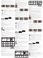
1 Apparecchio elettrico
2 Pulsante per test
3 LED di stato della batteria
4 LED di stato della
recinzione
5 Cavo
6 Clip di contatto
7 Piastra di fissaggio
14
3
2
67
5
1. Tagliare le due estremità del
nastro per recinzioni il più diritte
possibile in modo che coincidano
(senza sovrapporsi!).
2. Posizionare centralmente la
piastra di fissaggio dietro le due
estremità del nastro. Staccare la
pellicola protettiva dei nastri e pre-
merli bene. I nastri per recinzioni
non devono sovrapporsi.
3. Posizionare la clip di contatto
per la creazione del ponte elettrico.
SUGGERIMENTO: Se si desidera testare il funzionamento in un punto qualsiasi della recinzione, procedere come segue:
Con un oggetto metallico (come un chiodo, un cacciavite o simili) bypassare per almeno 10 secondi le due strisce di
contatto del nastro nel punto che si vuole testare.
Contemporaneamente controllare l'apparecchio elettrico:
a. Se il LED di stato della recinzione dopo 10 secondi inizia a lampeggiare con luce rossa, il funzionamento della
recinzione nel punto testato è corretto.
b. Se non si ottiene alcuna indicazione (o il LED di stato della recinzione lampeggia con luce verde alla pressione del
pulsante di test) significa che non c’è un collegamento elettrico continuo nella recinzione. Controllare tutti i punti
di contatto ed eseguire nuovamente il test.
L’intera recinzione non deve obbligatoriamente formare un circuito chiuso, per cui un collegamento delle estremità
aperte non è necessario, ma aumenta l'ecacia. Il nastro per recinzioni in eccesso può essere tagliato facilmente
con una normale forbice.
Consiglio pratico: Per questa ragione, con la recinzione elettrica contro le lumache è possibile proteggere dalle
lumache anche i bordi dei prati senza formare un circuito chiuso con il nastro.
Accertarsi che le estremità tagliate non provochino un cortocircuito. È importante soprattutto in caso di sottofondi
metallici. A tale scopo, alle estremità si deve semplicemente rimuovere un pezzo dei due nastri conduttivi in alluminio
dal materiale di supporto (circa 2 mm).
7.3. Collegamento dell'apparecchio elettrico
Collegare la clip di contatto
dell'apparecchio elettrico con la
piastra di fissaggio.
Fissare l'apparecchio elettrico con
l'ausilio della vite fornita in modo
che sia sempre sospeso (apertura
per sospensione sul lato posteriore)
per garantire la tenuta ermetica.
Suggerimento: Se non è possibile
fissare l'apparecchio all’aiuola, è
possibile fissarlo a un listello di legno
ausiliario conficcato nel terreno.
Premere il pulsante di test per
testare il funzionamento della
recinzione. Se l’installazione è stata
eseguita correttamente, il LED di
indicazione dello stato della recin-
zione lampeggia con luce verde
(vedere il capitolo 8. Uso).
8. Uso
8.1. Accensione dell'apparecchio elettrico
Con l’inserimento della batteria, l'apparecchio si attiva automaticamente ed è subito pronto per l’uso.
8.2. Stato della recinzione
• In caso di corretta installazione del nastro per recinzioni, il LED di indicazione lampeggia
con luce verde.
• In caso di anomalia (corto circuito) il LED di indicazione lampeggia con luce rossa. Questo
significa che in un punto della recinzione c’è un collegamento elettrico diretto tra i due
nastri di contatto (ad esempio causato da chiusura di contatto metallica, prolungamento
non effettuato correttamente, fitta vegetazione nella recinzione o simili). Controllare l’intera
recinzione e rimuovere il cortocircuito.
CHECK
8.3. Stato della batteria
• Se la batteria ha una tensione suciente, alla pressione del pulsante di test il LED di indicazio-
ne lampeggia con luce verde.
• In caso di bassa tensione della batteria, alla pressione del pulsante di test il LED di indicazione
lampeggia con luce rossa. Se la batteria è scarica, il LED di indicazione è acceso con luce rossa
fissa. In entrambi i casi, sostituire immediatamente la batteria.
8.4. Pulsante di test
• Per risparmiare energia, i LED di indicazione lampeggiano in modo permanente solo in caso di
anomalia(problema nella recinzione, batteria scarica).
• Premendo il pulsante di test è però possibile testare in qualsiasi momento lo stato della
recinzione e della batteria.
9. Uso di più recinzioni con un apparecchio elettrico
In caso di necessità, è possibile collegare più recinzioni distinte con un connettore per aiuole (art. 291126) che di
conseguenza possono essere gestite con un unico apparecchio elettrico.
Questa soluzione è utile, ad esempio, se si devono recintare aiuole distinte situate una accanto all'altra.
L'apparecchio elettrico viene collegato a un'aiuola. Un’altra aiuola viene collegata con l'ausilio dell'apposito
connettore (art. 291126) e alimentata con la corrente elettrica.
Il connettore per aiuole è costituito da due clip di contatto collegate con un cavo e da due piastre di fissaggio. Il
montaggio delle piastre di fissaggio e delle clip di contatto è descritto nei capitoli 7.2 e 7.3.
Collegamento di ulteriori aiuole:
Connettore per aiuole (art. 291126)
Connettore per aiuole (art. 291126)
Rispettare sempre la lunghezza massima consentita della recinzione di 30 m. Oltre tale misura. l'effetto della
recinzione si riduce e la durata di vita della batteria può ridursi considerevolmente.
10. Pulizia e manutenzione
10.1. Rimozione della bava delle lumache
Se sono presenti molte lumache, è possibile che la loro bava si depositi sul nastro. Questo può influire sul funziona-
mento della recinzione e a concentrazioni elevate ha effetti negativi sulla durata di vita della batteria. Rimuovere la
bava molle con una spugna o uno strofinaccio bagnati, solo quando il tempo è umido. Non si deve mai grattare via la
bava essiccata, poiché si provocherebbero danni ai conduttori metallici del nastro per recinzioni.
10.2. Rimozione della vegetazione
La vegetazione (erba, foglie...) può creare ponti elettrici e influire negativamente sul funzionamento. Inoltre, parti di
piante potrebbero essere utilizzate dalle lumache come “scale” per oltrepassare la recinzione. Pertanto, è necessario
tagliare regolarmente eventuale vegetazione.
11. Manutenzione e riparazione
11.1. Sostituzione della batteria
Quando i livello della batteria è basso, la batteria a blocco da 9 V deve essere sostituita. Quando si sostituisce la
batteria, accertarsi che il coperchio venga riposizionato e avvitato correttamente per garantire la tenuta ermetica
dell'alloggiamento.
12. Difetti e possibili soluzioni
12.1. Parti della recinzione o l’intera recinzione vengono oltrepassate dalle lumache
Controllare il passaggio elettrico in tutti i punti di contatto. Eseguire il test descritto al punto 7.2 per localizzare il
punto difettoso.
12.2. Il LED di indicazione della recinzione lampeggia costantemente con luce rossa
È presente un cortocircuito sul nastro della recinzione (le due strisce di contatto sono state bypassate, ad esempio
con un corpo estraneo metallico o a causa di un’installazione scorretta dei componenti). Controllare l’installazione
per rimuovere il cortocircuito.
13. Dati tecnici
• Tensione d’esercizio: 9 V
• Durata della batteria: circa 6 mesi (per una recinzione lunga 10 m, senza vegetazione)
14. Smaltimento
Rifiuti elettronici
L'operatore è responsabile del corretto smaltimento dell'apparecchio alla fine del suo ciclo di vita.
Fare riferimento alle norme vigenti nei singoli paesi. Non gettare l'apparecchio tra i rifiuti domestici.
Nell'ambito della direttiva europea sullo smaltimento delle apparecchiature elettriche ed elettroniche
obsolete, l'apparecchio deve essere conferito gratuitamente presso i centri di raccolta comunali
o i servizi di smaltimento rifiuti. In alternativa può essere riconsegnato ai rivenditori specializzati
che offrono questo tipo di servizio. Lo smaltimento corretto rappresenta una tutela dell'ambiente e
contribuisce a prevenire ripercussioni dannose su uomo e ambiente.
Dichiarazione di conformità CE
La Albert KERBL GmbH dichiara che il prodotto/l‘apparecchio descritto in queste istruzioni è
conforme ai requisiti fondamentali e alle ulteriori disposizioni e direttive pertinenti. Il marchio CE
indica che sono state soddisfatte le direttive dell‘Unione Europea.
Team di esperti Hobbyfarming:
(PL) Instrukcja obsługi Elektryczne ogrodzenie przeciw ślimakom – Zestaw startowy #291130
1. Informacje ogólne
W przypadku prawidłowej instalacji elektryczne ogrodzenie przeciw ślimakom stanowi w przydomowym ogrodzie
barierę nie do pokonania dla wszelkiego rodzaju ślimaków. Dzięki niskiemu napięciu ogrodzenia wynoszącemu
9V (bateria blokowa) ślimaki nie doznają żadnych obrażeń, lecz odczuwają jedynie nieprzyjemne mrowienie, które
zmusza je do natychmiastowego odwrotu. Dla innych zwierząt oraz dla ludzi takie napięcie jest nieodczuwalne i jest
absolutnie nieszkodliwe.
2. Użytkowanie zgodne zprzeznaczeniem
Produkt wraz z jego osprzętem służą wyłącznie do odstraszania ślimaków. Nie przewiduje się innego zastosowania.
Modyfikacje techniczne systemu lub jego elementów składowych są niedopuszczalne!
3. Instrukcje dotyczące bezpieczeństwa
• Regularnie sprawdzać system pod kątem uszkodzeń. W razie potrzeby wymienić uszkodzone elementy!
• Zwinąć luźne kable, aby uniknąć potknięcia lub innych obrażeń ciała!
• Regularnie sprawdzać poziom naładowania baterii; wyciekające lub uszkodzone baterie natychmiast poddać
właściwej utylizacji!
• Elektryzator wolno zasilać wyłącznie baterią 9V. Zasilanie sieciowe jest niedopuszczalne.
4. Zakres dostawy
Elektryzator z podłączonym klipsem
kontaktowym i płytą mocującą
(art. 291125)
Taśma ogrodzenio-
wa 10m
(art. 291128)
Bateria 9V Śruba
mocująca
5. Akcesoria opcjonalne / artykuły zamienne
Elektryzator z
podłączonym
klipsem kontak-
towym i płytą
mocującą
(art. 291125)
10 m
Taśma ogro-
dzeniowa
(art. 291128)
20 m
Taśma ogro-
dzeniowa
(art. 291129)
Łączniki
ogrodzenia
(art. 291127)
Łączniki
grządkowe
(art. 291126)
1 Elektryzator
2 Przycisk Test
3 Dioda stanu
naładowania baterii
4 Dioda stanu
ogrodzenia
5 Kabel
6 Klips kontaktowy
7 Płyta mocująca
14
3
2
67
5
1. Obciąć obydwie końcówki taśmy
ogrodzeniowej możliwie prosto,
aby stykały się równo ze sobą (bez
zachodzenia na siebie!).
2. Pod obydwoma końcówkami
taśmy umieścić na środku płytę
mocującą. Odkleić z obydwu taśm
folię ochronną i mocno docisnąć
taśmy. Taśmy ogrodzeniowe nie
mogą na siebie nachodzić.
3. Założyć klips kontaktowy, aby
utworzyć mostek elektryczny.
PORADA: Chcąc sprawdzić dowolny odcinek ogrodzenia pod kątem działania, należy postępować w poniższy sposób:
Za pomocą metalowego przedmiotu (np. gwoździa, śrubokrętu itp.) zmostkować na co najmniej 10 sekund dwa paski
stykowe taśmy ogrodzeniowej w miejscu, które ma zostać sprawdzone.
Jednocześnie sprawdzić elektryzator:
a. Jeżeli po upływie 10 sekund dioda stanu ogrodzenia zacznie pulsować na czerwono, oznacza to, że ogrodzenie
działa w tym miejscu prawidłowo.
b. Jeżeli nie pojawi się żadne wskazanie (lub po naciśnięciu przycisku Test dioda stanu ogrodzenia będzie pulsować
na zielono), oznacza to brak ciągłości połączenia elektrycznego w ogrodzeniu. Sprawdzić wszystkie punkty styczne
i ponownie przeprowadzić test.
Całe ogrodzenie nie musi tworzyć pętli; połączenie luźnych końcówek nie jest konieczne, ale zwiększa to niezawod-
ność działania. Nadmiar taśmy ogrodzeniowej można obciąć po prostu nożyczkami domowymi.
Wskazówka praktyczna: Elektryczna taśma ogrodzeniowa umożliwia ochronę obrzeży trawników przed ślimakami
bez konieczności wykonania pętli z taśmy ogrodzeniowej.
Zwrócić uwagę, aby obcięte końcówki nie powodowały zwarcia. Jest to szczególnie istotne w przypadku podłoży
metalowych. W tym celu należy na końcówkach materiału nośnego usunąć kawałek obydwu taśm aluminiowych
przewodzących prąd (ok. 2 mm).
7.3. Podłączanie elektryzatora
Połączyć klips kontaktowy elektry-
zatora z płytą mocującą.
Za pomocą dołączonego wkrętu
zamontować elektryzator w pozycji
wiszącej (otwór do zawieszenia
znajduje się z tyłu), aby zapewnić
szczelność.
Wskazówka: Jeżeli zamontowanie
urządzenia na grządce nie
jest możliwe, wówczas można
zamocować urządzenie na desce
wbitej w ziemię.
Nacisnąć przycisk Test, aby spraw-
dzić działanie ogrodzenia.
W przypadku prawidłowej instalacji
dioda wskaźnikowa stanu ogro-
dzenia pulsuje na zielono (patrz
rozdział 8. Obsługa).
8. Obsługa
8.1. Włączanie elektryzatora
Po włożeniu baterii urządzenie zostaje automatycznie aktywowane i jest gotowe do pracy.
8.2. Stan ogrodzenia
• W przypadku prawidłowej instalacji taśmy ogrodzeniowej dioda wskaźnikowa pulsuje na zielono.
• W przypadku usterki (zwarcia) dioda wskaźnikowa pulsuje na czerwono. Oznacza to, że w
którymś miejscu ogrodzenia doszło do bezpośredniego połączenia elektrycznego między dwo-
ma taśmami kontaktowymi (np. wskutek zwarcia metalowym przedmiotem, nieprawidłowego
przedłużenia, intensywnego porośnięcia ogrodzenia przez roślinność itp.). Sprawdzić całe
ogrodzenie i usunąć przyczynę zwarcia.
CHECK
8.3. Stan naładowania baterii
• W przypadku wystarczającego napięcia baterii, po naciśnięciu przycisku Test dioda wskaźni-
kowa pulsuje na zielono.
• W przypadku niskiego napięcia baterii, po naciśnięciu przycisku Test dioda wskaźnikowa pul-
suje na czerwono. Przy rozładowanej baterii dioda wskaźnikowa świeci na czerwono światłem
ciągłym. W obydwu przypadkach należy bezzwłocznie wymienić baterię.
8.4. Przycisk Test
• Aby oszczędzać energię, diody wskaźnikowe pulsują nieprzerwanie tylko w przypadku usterki
(defekt ogrodzenia, rozładowana bateria).
• Przez naciśnięcie przycisku Test można w każdej chwili sprawdzić stan ogrodzenia i baterii.
9. Zasilanie kilku ogrodzeń jednym elektryzatorem
W razie potrzeby można połączyć kilka odrębnych ogrodzeń łącznikiem grządkowym (art. 291126) i zasilać ogrodzenia
z jednego elektryzatora.
Takie rozwiązanie można stosować na przykład wówczas, gdy mają być ogrodzone odrębne, sąsiadujące ze sobą grządki.
Elektryzator podłącza się wtedy do tylko jednej grządki. Kolejną grządkę podłącza się i zasila przy użyciu łącznika
grządkowego (art. 291126).
Łącznik grządkowy składa się z dwóch klipsów kontaktowych połączonych przewodem oraz dwóch płyt mocujących.
Montaż płyt mocujących i klipsów kontaktowych opisano w rozdziale 7.2 oraz 7.3.
Podłączanie kolejnych grządek:
Łącznik grządkowy (art. 291126)
Łącznik grządkowy (art. 291126)
Nie przekraczać maksymalnej długości ogrodzenia wynoszącej 30m. Jej przekroczenie może zmniejszyć skuteczność
ogrodzenia i znacznie skrócić czas użytkowania baterii.
10. Czyszczenieiutrzymywanie wdobrym stanie
10.1. Usuwanie śluzu ślimaków
W przypadku dużej liczby ślimaków taśma ogrodzeniowa może pokrywać się śluzem. Może on zakłócać skuteczność
działania ogrodzenia, a w dużej ilości negatywnie wpływać na czas użytkowania baterii. Namoczony śluz należy
usuwać mokrą gąbką lub ściereczką tylko przy wilgotnej pogodzie. Nigdy nie zdrapywać zaschniętego śluzu, ponieważ
można uszkodzić metaliczny przewodnik w taśmie ogrodzeniowej.
10.2. Usuwanie porostu roślinnego
Roślinność porastająca ogrodzenie (trawy, liście…) może tworzyć mostki elektryczne i negatywnie wpływać na działa-
nie ogrodzenia. Poza tym ślimaki mogą wykorzystywać odcinki roślin jako „drabinkę” do pokonania ogrodzenia.
Dlatego należy regularnie podcinać ewentualną roślinność.
11. Konserwacja i naprawa
11.1. Wymiana baterii
Przy niskim poziomie naładowania baterii należy wymienić baterię blokową 9V. Po wymienieniu baterii zwrócić
uwagę, aby prawidłowo założyć i przykręcić pokrywę w celu zapewnienia szczelności obudowy.
12. Błędy i możliwe rozwiązania
12.1. Odcinki ogrodzenia lub całe ogrodzenie są pokonywane przez ślimaki
Sprawdzić wszystkie punkty styczne pod kątem przepływu prądu. Przeprowadzić test opisany w punkcie 7.2, aby
zlokalizować uszkodzone miejsce.
12.2. Dioda wskaźnikowa ogrodzenia pulsuje permanentnie na czerwono
Powodem jest zwarcie w taśmie ogrodzeniowej (zmostkowanie dwóch pasków stykowych, na przykład metalowym
przedmiotem lub wskutek niewłaściwej instalacji elementów ogrodzenia).
Sprawdzić instalację, aby wyeliminować zwarcie.
13. Dane techniczne
• Napięcie robocze: 9 V
• Czas pracy baterii: ok. 6 miesięcy (przy długości ogrodzenia 10m, bez porośnięcia roślinnością)
14. Utylizacja
Złom elektroniczny
Prawidłowa utylizacja urządzenia oraz jego prawidłowe funkcjonowanie należy do właściciela
użytkującego. Przestrzegajcie obowiązujących przepisów danego kraju. Urządzenie nie może być
utylizowane z odpadami domowymi. W ramach dyrektywy UE dotyczącej używanych urządzeń
elektrotechnicznych i elektronicznych, urządzenie należy przekazać do gminnych punktów zbiorczych
wzglętnie punktów zbioru surowców wtórnych lub też może zostać przekazane do sklepów specjal-
istycznych oferujących usługę przyjmowania zużytych urządzeń. Prawidłowa utylizacja służy ochronie
środowiska naturalnego oraz zapobiega możliwości powstania szkodliwych skutków dotyczących
człowieka i środowiska naturalnego.
Deklaracja zgodności CE
Niniejszym firma Albert KERBL GmbH oświadcza, że produkt/urządzenie opisane w niniejszej
instrukcji odpowiada podstawowym wymogom oraz pozostałym, właściwym wytycznym i dyrekty-
wom. Znak CE poświadcza spełnienie wymogów dyrektyw Unii Europejskiej.
Zespół ekspertów ds. rolnictwa hobbystycznego:
291130=BA_Schneckenzaun_Starter-Set_202203
-
 1
1
-
 2
2


Kerbl 291130 Electric Slug Fence Starter Kit Benutzerhandbuch
- Typ
- Benutzerhandbuch
in anderen Sprachen
Verwandte Artikel
Andere Dokumente
-
 Gallagher FenceAlarm Instructions Manual
-
AKO BA-1060 Benutzerhandbuch
-
Petsafe PIG20-11041 Bedienungsanleitung
-
 Fi-Shock ESP2M-FS Installationsanleitung
-
-
Keter Malaga Assembly Instructions Manual
-
-
-
-
 Heras Delta 3a Installationsanleitung


