Bodensteckdosen Systemtechnik 76 A-Series Benutzerhandbuch
- Typ
- Benutzerhandbuch

Bedienungsanleitung
Instruction Manual
76er A-Serie
76 A-Series

2
Inhalt/Contents
Technische Daten ����������������������������������� 3
Produktbeschreibung ���������������������������� 4
Montageanleitung ����������������������������������� 5
Gebrauchshinweise ������������������������������ 21
Technical specifications ............................. 3
Product description .................................... 4
Assembly instructions ............................. 13
Instructions for use .................................. 21

3
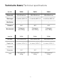
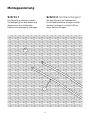
Art.-Nr. 7601A 7602A 7604A
Einbaumaße 100 x 100 x 82 mm 200 x 100 x 82 mm 200 x 200 x 82 mm
Zuleitungen 2 x seitlich, M25 x 1,5 4 x seitlich, M25 x 1,5 4 x seitlich, M25 x 1,5
Nivellierbar –––
Schutzart IP67 IP67 IP67
Belastbarkeit Flächenlast
max� 900 kg
Flächenlast
max� 900 kg
Flächenlast
max� 900 kg
Technische Daten/Technical specifications
Item No 7601A 7602A 7604A
Instl dim 100 x 100 x 82 mm 200 x 100 x 82 mm 200 x 200 x 82 mm
Supply line 2 x lateral, M25 x 1,5 4 x lateral, M25 x 1,5 4 x lateral, M25 x 1,5
Height adj –––
Protection IP67 IP67 IP67
Load Area load max.
900 kg
Area load max.
900 kg
Area load max.
900 kg

4
1
2
3
4
5
6
1
2
3
4
5
6
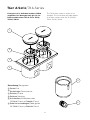
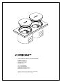
Bezeichnung/Designation:
Deckel/Lid
Geräteträger/Device carrier
Rahmen/Frame
Gehäuse/Housing
Aufsatztubus/Attachment tube
(2 Stück/Pieces → Zubehör/Parts)
Kabelverschraubungen/Cable glands
(4 Stück/Pieces → Zubehör/Parts)
76er A-Serie/ 76 A-Series
Exemplarisch ist die Bodensteckdose 7602A
abgebildet. Das Montageprinzip gilt für alle
Bodensteckdosen der 76er A-Serie: 7601A,
7602A, 7604A.
The 7602A floor socket is shown as an
example. The installation principle applies
to all floor sockets from the 76 A-Series:
7601A, 7602A, 7604A.

5
Montageanleitung
L
SP
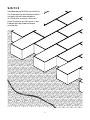
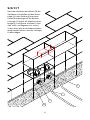
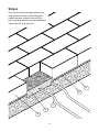
Schritt 1
Den Deckel entnehmen und den
Geräteträger von dem Gehäuse
abmontieren� Anschließend die
Kabelverschraubungen anbringen�
Schritt 2 (Vorbereitungen)
Vor dem Pflastern die Einbauposition
für die Bodensteckdose festlegen und die
flexiblen Leitungen (L) im Splitt (SP) zu
dieser Position verlegen�

6
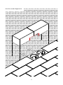
Schritt 3
Den Bodenbelag (B) (Pflastersteine) bis
zur Einbauposition der Bodensteckdose
verlegen und die Bodensteckdose
als Platzhalter einsetzen� Alternativ
einen Platzhalter aus Polystyrol in den
Einbaumaßen der Bodensteckdose
zuschneiden�

7
L
B
M
K
SP
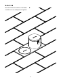
Schritt 4
Anschließend die Plastersteinreihe
zu Ende verlegen, die Bodensteckdose/
den Platzhalter entnehmen und ein
Mörtelbett (M) an der Einbauposition,
auf den verdichteten Untergrund (K)
(z. B. Kies) gießen�

8
L
M SP
6
4
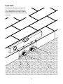
Schritt 5
Hiernach die flexiblen Leitungen (L)
durch die Kabelverschraubungen
in das Gehäuse einführen und die
Bodensteckdose in das Mörtelbett (M)
einsetzen�

9
6
M
B
K
SP
W
Schritt 6
Die Position der Bodensteckdose vor
dem Aushärten des Mörtels (M) mit
der Wasserwaage (W) überprüfen�
Achtung: Die Höhe des Mörtelbetts (M)
muss so vermessen werden, dass die
Bodensteckdose und der Belag (B)
bündig sind (fluchtend sind)!

10
L
M
6
4
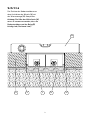
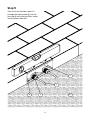
Schritt 7
Nach dem Aushärten des Mörtels (M) die
Steckdosen anschließen und den Geräte-
träger in das Gehäuse montieren�
Danach Aussparungen für die flexiblen
Leitungen (L) und für die Kabelverschrau-
bungen in die Steine schneiden (siehe
Abb. unten und Gegenansicht rechts),
so dass diese plan an die Bodensteckdose
gelegt werden können, ohne die Leitungen
zu beschädigen�

11
Ansicht von der Gegenseite.

12
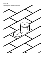
Schritt 8
Mit dem Pflastern fortfahren� Die Boden-
steckdose ist nun erfolgreich eingebaut�

13
Assembly Instructions
L
SP
Step 1
Remove the lid and dismantle the device
carrier from the housing � Then attach
the cable glands �
Step 2 (Preparations)
Before paving, determine the installation
position for the floor socket and lay the
flexible cables (L) in the gravel (SP) to this
position�

14
Step 3
Lay the floor covering (B) (paving stones)
up to the installation position of the floor
socket and use the floor socket as a place-
holder� Alternatively, cut a polystyrene
placeholder in the size of the installation
dimensions of the floor socket�

15
L
B
M
K
SP
Step 4
Then lay the row of paving stones to the
end, remove the floor socket/the place-
holder and pour a bed of mortar (M) at
the installation position on the compacted
subsurface (K) (e. g. gravel).

16
L
M SP
6
4
Step 5
Then insert the flexible cables (L)
through the cable glands into the
housing and insert the floor socket
into the mortar bed (M)�

17
6
M
B
K
SP
W
Step 6
Before the mortar (M) hardens, check
the position of the floor socket with the
spirit level (W)�
Attention: The height of the mortar bed
(M) must be measured so that the floor
socket and the covering (B) are flush
(are in alignment)!

18
L
M
6
4
Step 7
After the mortar (M) has hardened,
connect the sockets and mount the device
carrier in the housing � Then cut the
recesses for the flexible cables (L) and for
the cable glands in the stones so that
they can be laid flat on the floor socket
without damaging the cables (see figure
below and opposite view on the right)�

19
View from the opposite side.

20
Step 8
Continue paving� The floor socket is now
successfully installed�
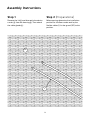
Seite wird geladen ...
Seite wird geladen ...
-
 1
1
-
 2
2
-
 3
3
-
 4
4
-
 5
5
-
 6
6
-
 7
7
-
 8
8
-
 9
9
-
 10
10
-
 11
11
-
 12
12
-
 13
13
-
 14
14
-
 15
15
-
 16
16
-
 17
17
-
 18
18
-
 19
19
-
 20
20
-
 21
21
-
 22
22


Bodensteckdosen Systemtechnik 76 A-Series Benutzerhandbuch
- Typ
- Benutzerhandbuch
in anderen Sprachen
Verwandte Artikel
Andere Dokumente
-
Midmark 204 Examination Table Installationsanleitung
-
 Minebea Intec Weighbridge Cable Junction Box PR 6021/18 Bedienungsanleitung
-
Panasonic KX-TGA914EX Bedienungsanleitung
-
-
 Stahl 8118/2.2 Ex i Operating Instructions Manual
-
-
Videotec MAXIMUS MBX Benutzerhandbuch
-
 Stahl ORCA01 Bedienungsanleitung
-
Dimplex HMSF Bedienungsanleitung


