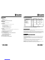
Würth WWS 3-POWER Instruction and Maintenance Manual
- Kategorie
- Schweißsystem
- Typ
- Instruction and Maintenance Manual


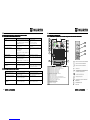
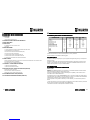
Dichiarazione
DichiarazioneDichiarazione
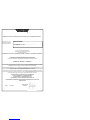
Dichiarazione di Conformità
di Conformità di Conformità
di Conformità
Declaration of conformity
Declaration of conformityDeclaration of conformity
Declaration of conformity
Konformitätserklärung
KonformitätserklärungKonformitätserklärung
Konformitätserklärung
dichiara che la macchina
declares that the machine
Erklärt, daß die Maschine
è conforme alle condizioni delle Direttive:
complies with the conditions of the Directives:
den folgenden Richtlinien:
e inoltre dichiara che sono state applicate le seguenti norme armonizzate:
and also declares that the following harmonised standards have been applied:
entspricht, und erklärt außerdem, daß die folgenden harmonisierten Normen angewandt wurden:
Questo generatore e’ stato progettato per essere utilizzato in ambiente professionale ed industriale anche secondo normativa EN609-
74-10.Per altri tipi di applicazione contattare il costruttore. Nel caso in cui siano individuati distrurbi elettromagnetici e’ responsabilità’
dell’utilizzatore della macchina risolvere la situazione con l’assistenza tecnica del costruttore
This generator has been designed to be used in a professional and industrial environment according to standard EN60974-10. For all
other types of application contact the manufacturer. If any eletromagnetic disturbances are encountered, the user of the machine is
responsible for solving the situation with the technical assistance of the manufacturer
Dieser Generator wurde für den Einsatz in professioneller und industrieller Umgebung gemäß EN60974-10 entwickelt.
Für jede andere Verwendung den Hersteller kontaktieren. Im Falle von elektromagnetischen Störungen obliegt es dem
Benutzer der Maschine diese unter technischer Assistenz des Herstellers zu beseitigen.
QUALSIASI MODIFICA ALLA MACCHINA SENZA L’AUTORIZZAZIONE
DI Würth Srl RENDERÀ’ NULLA QUESTA DICHIARAZIONE
ANY MODIFICATION OF THE MACHINE WITHOUT THE
AUTHORISATION OF Würth Srl RENDERS THIS DECLARATION VOID
JEDE VERÄNDERUNG DER MASCHINE OHNE GENEHMIGUNG DER FIRMA Würth Srl ANNULLIERT
DIESE ERKLÄRUNG
2006/95/CEE – 2006/114/CE – 2004/108/CE - 92/31/CEE – 93/68/CEE — 2002/96/CEE – 2002/95/CEE
EN 60974-10 – EN 60974-1 – EN 60204-1
WÜRTH Srl Via Stazione 51 39044 Egna (Bz) Tel.0471/828111 Fax: 0471/828600 www.wuerth.it
WWS 3-POWER
Art: 5952 351 2 S/N<<<<<<<<<<..
Date 14/11/2011 Santer Harald
Würth Srl

48
GB
AVVERTENZE GENERALI PER LO SMALTIMENTO
AVVERTENZE GENERALI PER LO SMALTIMENTOAVVERTENZE GENERALI PER LO SMALTIMENTO
AVVERTENZE GENERALI PER LO SMALTIMENTO
GENERAL WARNINGS FOR DISPOSAL
GENERAL WARNINGS FOR DISPOSALGENERAL WARNINGS FOR DISPOSAL
GENERAL WARNINGS FOR DISPOSAL
ALLGEMEINE HINWEISE ZUR ENTSORGUNG
ALLGEMEINE HINWEISE ZUR ENTSORGUNGALLGEMEINE HINWEISE ZUR ENTSORGUNG
ALLGEMEINE HINWEISE ZUR ENTSORGUNG
AVERTISSEMENT GÉNÉRAL POUR L’ECOULEMENT
AVERTISSEMENT GÉNÉRAL POUR L’ECOULEMENTAVERTISSEMENT GÉNÉRAL POUR L’ECOULEMENT
AVERTISSEMENT GÉNÉRAL POUR L’ECOULEMENT
ADVERTENCIA GENERAL PARA SU ELIMINACION Y DESGUACE
ADVERTENCIA GENERAL PARA SU ELIMINACION Y DESGUACEADVERTENCIA GENERAL PARA SU ELIMINACION Y DESGUACE
ADVERTENCIA GENERAL PARA SU ELIMINACION Y DESGUACE
1
I

2
I
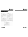
INDICE GENERALE
INDICE GENERALE INDICE GENERALE
INDICE GENERALE
1.0 SICUREZZA
1.1 AVVERTENZE
1.2 ISTRUZIONI PER LA SICUREZZA
2.0 CARATTERISTICHE GENERALI/ELETTRICHE
3.0 RECLAMI
4.0 ALLACCIAMENTO
4.1 ALLACCIAMENTO PRIMARIO E COLLEGAMENTO
4.2 MESSA A TERRA
5.0 MESSA IN SERVIZIO
5.1 COMANDI PANNELLO FRONTALE/REGOLAZIONE INTERNE
5.2 DESCRIZIONE TARGA DATI
5.3 DISPOSIZIONE SALDATURA ELETTRODI (MMA)
5.4 DISPOSIZIONE SALDATURA TIG
5.5 DISPOSIZIONE SALDATURA MIG CON GAS
5.6 DISPOSIZIONE SALDATURA MIG SENZA GAS
5.7 DISPOSIZIONE SALDATURA MIG SINERGICO
6.0 FIGURE
6.1 DISTANZA POSTERIORE LATERALI DA MANTENERE DURANTE LA SALDATURA
6.2 CICLO DI INTERMITTENZA E SOVRATEMPERATURA
7.0 INCONVENIENTI DI SALDATURE E FUNZIONAMENTO
7.1 POSSIBILI DIFETTI DI SALDATURA
7.2 POSSIBILI INCONVENIENTI DI FUNZIONAMENTO
8.0 LISTA COMPONENTI E VISTE ESPLOSE (INGLESE)
8.1 LISTA COMPONENTI (INGLESE)
8.2 VISTA ESPLOSA GENERATORE (INGLESE)
8.3 LISTA COMPONENTI GRUPPO TRAINAFILO (INGLESE)
9.0 SCHEMI ELETTRICI GENERALI (INGLESE)
10.0 CURVE TENSIONE/CORRENTE (INGLESE)
47
GB
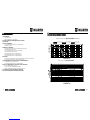
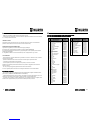
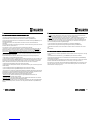
10.0 VOLTAGE/CURRENT CURVES
10.0 VOLTAGE/CURRENT CURVES10.0 VOLTAGE/CURRENT CURVES
10.0 VOLTAGE/CURRENT CURVES
St atic characte ris tic M iggy 17 1 1F M M A- T IG M OD E
0
10
20
30
40
50
60
0 50 100 150 200 250
Cur r e nt ( A )
Ioutmax,TIG MODE Ioutmax, MMA MODE Iout90A, TIG MODE
Iout90A, MMA MODE Ioutmin, TIG MODE Ioutmin, MMA MODE
St at ic C haract eristic M iggy 171 M IG M OD E
0
5
10
15
2 0
2 5
0 5 0 10 0 15 0 2 00 2 5 0 3 0 0
Cur r e nt ( A)
VOLTAGE (V)
CURRENT (A)
VOLTAGE (V)
CURRENT (A)
WWS 3-POWER MMA MODE
WWS 3-POWER TIG MODE

46
GB
9.0 WIRING DIAGRAM WWS 3
9.0 WIRING DIAGRAM WWS 39.0 WIRING DIAGRAM WWS 3
9.0 WIRING DIAGRAM WWS 3-
--
-POWER 1F
POWER 1FPOWER 1F
POWER 1F
3
I
1.0
1.0 1.0
1.0 SICUREZZA
SICUREZZASICUREZZA
SICUREZZA
1.1
1.1 1.1
1.1 AVVERTENZE
AVVERTENZEAVVERTENZE
AVVERTENZE
LO SHOCK ELETTRICO PUÒ UCCIDERE
- Disconnettere la macchina dalla rete di alimentazione prima di intervenire sul generatore.
- Non lavorare con i rivestimenti dei cavi deteriorati.
- Non toccare le parti elettriche scoperte.
- Assicurarsi che tutti i pannelli di copertura del generatore di corrente siano ben fissati al
loro posto quando la macchina è collegata alla rete di alimentazione.
- Isolate Voi stessi dal banco di lavoro e dal pavimento (ground): usate scarpe e guanti
isolanti.
- Tenete guanti, scarpe, vestiti, area di lavoro, e questa apparecchiatura puliti ed asciutti.
I CONTENITORI SOTTO PRESSIONE POSSONO ESPLODERE SE SALDATI.
Quando si lavora con un generatore di corrente:
- non saldare contenitori sotto pressione.
- non saldare in ambienti contenenti polveri o vapori esplosivi.
LE RADIAZIONI GENERATE DALL’ARCO Dl SALDATURA POSSONO DANNEGGIA-
RE GLI OCCHI E PROVOCARE BRUCIATURE ALLA PELLE.
- Proteggere gli occhi ed il corpo adeguatamente.
- È indispensabile per i portatori di lenti a contatto proteggersi con apposite lenti e ma-
schere.
IL RUMORE PUÒ’ DANNEGGIARE L’UDITO.
- Proteggersi adeguatamente per evitare danni.
I FUMI ED I GAS POSSONO DANNEGGIARE LA VOSTRA SALUTE.
- Tenere il capo fuori dalla portata dei fumi.
- Provvedere per una ventilazione adeguata dell’area di lavoro.
- Se la ventilazione non è sufficiente, usare un aspiratore che aspiri dal basso.
IL CALORE, GLI SCHIZZI DEL METALLO FUSO E LE SCINTILLE POSSONO PROVO-
CARE INCENDI.
- Non saldare vicino a materiali infiammabili.
- Evitare di portare con sé qualsiasi tipo di combustibile come accendini o fiammiferi.
- L’arco di saldatura può provocare bruciature. Tenere la punta dell’elettrodo lontano dal
proprio corpo e da quello degli altri.
È vietato l’utilizzo e l’avvicinamento alla macchina da parte di persone portatori di stimola-
tori elettrici (PACE MAKERS).
AVVERTENZA POSIZIONAMENTO PRECARIO
- Se il generatore cade può causare infortuni.
- Non mettere in funzione o spostare il generatore nel caso si trovi in posizione precaria.
Non posizionare il generatore su piani inclinati superiori a 10°.

4
I
1.2
1.2 1.2
1.2 ISTRUZIONI
ISTRUZIONIISTRUZIONI
ISTRUZIONI
PER
PERPER
PER
LA
LALA
LA
SICUREZZA
SICUREZZASICUREZZA
SICUREZZA
PREVENZIONE USTIONI
Per proteggere gli occhi e la pelle dalle bruciature e dai raggi ultravioletti:
- portare occhiali scuri. Indossare vestiti, guanti e scarpe adeguate.
- usare maschere con i lati chiusi, con lenti e vetri di protezione a norme (grado di prot. DIN 10).
- avvisare le persone circostanti di non guardare direttamente l’arco.
PREVENZIONE INCENDI
La saldatura produce schizzi di metallo fuso.
Prendere le seguenti precauzioni per evitare incendi:
- assicurarsi un estintore nell’area di saldatura.
- allontanare il materiale infiammabile dalla zona immediatamente vicina all’area di saldatura.
- raffreddare il materiale saldato o lasciarlo raffreddare prima di toccarlo o di metterlo a contatto
con materiale combustibile
- non usare mai la macchina per saldare contenitori di materiale potenzialmente infiammabile.
Questi contenitori devono essere puliti completamente prima di procedere alla saldatura.
- ventilare l’area potenzialmente infiammabile prima di usare la macchina.
- non usare la macchina in atmosfere che contengano concentrazioni elevate di polveri, gas
infiammabili o vapori combustibili.
PREVENZIONE CONTRO SHOCK ELETTRICI
Prendere le seguenti precauzioni quando si opera con un generatore di corrente:
- tenere puliti se stessi ed i propri vestiti.
- non essere a contatto con parti umide e bagnate quando si opera con il generatore.
- mantenere un isolamento adeguato contro gli shock elettrici. Se l’operatore deve lavorare in
ambiente umido, dovrà usare estrema cautela, vestire scarpe e guanti isolanti.
- controllare spesso il cavo di alimentazione della macchina: dovrà essere privo di danni all’iso-
lante. I CAVI SCOPERTI SONO PERICOLOSI. Non usare la macchina con un cavo di alimen-
tazione danneggiato; è necessario sostituirlo immediatamente.
- se c’è la necessità di aprire la macchina, prima staccare l’alimentazione. Aspettare 5 minuti
per permettere ai condensatori di scaricarsi. Non rispettare questa procedura può esporre l’o-
peratore a pericolosi rischi di shock elettrico.
- non operare mai con la saldatrice, se la copertura di protezione non è al suo posto.
- assicurarsi che la connessione di terra del cavo di alimentazione, sia perfettamente efficiente.
Questo generatore è stato progettato per essere utilizzato in ambiente professionale ed indu-
striale. Per altri tipi di applicazione contattare il costruttore. Nel caso in cui disturbi elettroma-
gnetici siano individuate è responsabilità dell’utilizzatore della macchina risolvere la situazione
con l’assistenza tecnica del costruttore.
45
GB
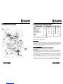
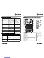
6348100000
631860000
664620000
634810000
634700000
632370000
634690000
634800000
665350000
632360000
632560000
8.3 WIRE FEEDER LIST
8.3 WIRE FEEDER LIST 8.3 WIRE FEEDER LIST
8.3 WIRE FEEDER LIST OF
OFOF
OF COMPONENTS
COMPONENTS COMPONENTS
COMPONENTS
(1)
(2)
(3)
(4)
(5)
(6)
(7) (8)
(9) (10)

44
GB
8.2
8.2 8.2
8.2 EXPLODED VIEW
EXPLODED VIEW EXPLODED VIEW
EXPLODED VIEW WWS 3
WWS 3 WWS 3
WWS 3-
--
-POWER
POWERPOWER
POWER
56
5
I
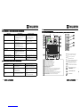
2.0 CARATTERISTICHE GENERALI/
2.0 CARATTERISTICHE GENERALI/2.0 CARATTERISTICHE GENERALI/
2.0 CARATTERISTICHE GENERALI/ELETTRICHE
ELETTRICHEELETTRICHE
ELETTRICHE
I Dati sono determinati a 40° ambiente per simulazione
N.B Il Generatore non e’ adatto a sgelare tubi
3.0
3.0 3.0
3.0 RECLAMI
RECLAMIRECLAMI
RECLAMI
Reclami per danneggiamento durante il trasporto: Se la Vs. apparecchiatura viene danneggiata durante
la spedizione, dovete inoltrare un reclamo al Vs: Tutte le apparecchiature spedite da WURTH sono state
sottoposte ad un rigoroso controllo di qualità. Tuttavia se la Vs. apparecchiatura non dovesse funzionare
correttamente, consultate la sezione RICERCA GUASTI di questo manuale. Se il difetto permane, con-
sultate il Vs. concessionario autorizzato.
4.0 ALLACCIAMENTO
4.0 ALLACCIAMENTO4.0 ALLACCIAMENTO
4.0 ALLACCIAMENTO
4.1 ALLACCIAMENTO PRIMARIO
4.1 ALLACCIAMENTO PRIMARIO 4.1 ALLACCIAMENTO PRIMARIO
4.1 ALLACCIAMENTO PRIMARIO E
EE
E
COLLEGAMENTO
COLLEGAMENTOCOLLEGAMENTO
COLLEGAMENTO
INSTALLAZIONE
ATTENZIONE:Questa apparecchiatura in CLASSE A non e’ destinata all’uso in ambienti residenziali
dove la potenza elettrica e’ fornita dal sistema pubblico di alimentazione a bassa tensione. Ci possono
essere potenziali difficoltà a garantire la compatibilità elettromagnetica di questi ambienti a causa di di-
sturbi condotti e irradiati.
Questo generatore non rispetta i limiti della IEC 61000-3-12. Se collegato alla rete BT industriale pubbli-
ca è responsabilità dell'installatore o dell'utilizzatore assicurarsi, previa consultazione dell'Ente distributo-
re, se lo stesso è collegabile.
Il buon funzionamento del generatore è assicurato da una sua adeguata installazione; è necessario quin-
di:
- Sistemare la macchina in modo che non sia compromessa la circolazione d’ aria assicurata dal moto-
ventilatore interno (i componenti interni necessitano di un adeguato raffreddamento) (Section 6.3)
Tensione di alimentazione
Fasi
Frequenza
Potenza nominale DC 40%
Potenza nominale DC 60%
Tensione a vuoto
Fusibili di protezione
Campo di regolazione corrente
Corrente saldatura DC 40%
Corrente saldatura DC 60%
Corrente saldatura DC 100%
Lunghezza
Larghezza
Altezza
Peso
V
-
Hz
KVA
KVA
V
A
A
A
A
A
mm
mm
mm
Kg
GENERATORE
ELETTRODO
230
1
50/60
6,5
5,7
4,4
16
25 - 150
150
130
105
230
1
50/60
5
3,8
3
16
8 - 160
160
130
105
TIG
230
1
50/60
5,7
4,5
3,7
16
35 - 160
160
135
105
MIG
500
190
400
19

6
I
- Evitare che il ventilatore immetta nella macchina depositi o polveri.
- E’ bene evitare urti, sfregamenti, ed in maniera assoluta l’ esposizione a stillicidi, fonti di calore eccessi-
ve, o comunque situazioni anomale.
TENSIONE DI RETE
Il generatore funziona per tensioni di rete che si discostano del 15% del valore nominale della rete
(tensione nominale 230V, tensione minima 185V, tensione massima 275V).
ALIMENTAZIONE DA MOTOGENERATORE
Il generatore è progettato per funzionare alimentato da gruppi elettrogeni.
E’ importante che il gruppo elettrogeno soddisfi le condizioni riportate (Section 2.0)
E’ sconsigliato impiegare questa macchina con gruppi elettrogeni che non rispettino queste condizioni
perché si può danneggiare.
E’ consigliabile accendere la macchina solamente dopo che il motogeneratore e’ gia’ avviato.
COLLEGAMENTO
- Prima di effettuare connessioni elettriche tra il generatore di corrente e l’ interruttore di linea, accertarsi
che quest’ ultimo sia aperto.
- Il quadro di distribuzione deve essere conforme alle normative vigenti nel paese di utilizzo
- L’ impianto di rete deve essere di tipo industriale.
- il cavo multipolare è provvisto di una spina tipo G32 (shuko) a norme UNI 47 166/68.
Predisporre una apposita presa modello SHUKO 16A che preveda l’ alloggiamento di conduttori da
2.5mm² di sezione.
- Per i cavi più lunghi maggiorare opportunamente la sezione del conduttore.
A monte, l’ apposita presa di rete dovrà avere un adeguato interruttore munito di fusibili ritardati.
4.2 MESSA
4.2 MESSA 4.2 MESSA
4.2 MESSA A
AA
A
TERRA
TERRATERRA
TERRA
- Per la protezione degli utenti la saldatrice dovrà essere assolutamente collegata correttamente all’im-
pianto di terra (NORMATIVE INTERNAZIONALI DI SICUREZZA).
- E’ indispensabile predisporre una buona messa a terra tramite il conduttore giallo-verde del cavo di ali-
mentazione, onde evitare scariche dovute a contatti accidentali con oggetti messi a terra.
- Lo chassis (che è conduttivo) è connesso elettricamente con il conduttore di terra; non collegare corret-
tamente a terra l’ apparecchiatura può provocare shock elettrici pericolosi per l’utente.
43
GB
8.0 LIST OF COMPONENTS AND EXPLODED VIEW
8.0 LIST OF COMPONENTS AND EXPLODED VIEW8.0 LIST OF COMPONENTS AND EXPLODED VIEW
8.0 LIST OF COMPONENTS AND EXPLODED VIEW
8.1 LIST OF COMPONENTS WWS 3
8.1 LIST OF COMPONENTS WWS 38.1 LIST OF COMPONENTS WWS 3
8.1 LIST OF COMPONENTS WWS 3-
--
-POWER
POWERPOWER
POWER
DESCRIPTION CODE
1
2
3
4
5
6
7
8
9
10
11
12
13
14
15
16
17
18
19
20
21
22
23
24
25
26
27
28
29
30
31
32
33
34
35
36
37
38
39
40
41
42
43
44
45
Instrumental Support
Instrumental Plate
Instruments panel protection
Fixed Socket
Knob d.29
Front panel
Fixed sockets support
Logic pcb
Motor Wire Feeder
Resistance
Screw
Copper Connection
Inverter Support
Base
Auxiliary transformer
Output inductance
Spacer
Motor pcb
Spacer
Regulation pcb
Cover
Support
Thermostat
Inverter pcb
Filter pcb
Gas Connector support
Cap
Switch
Fuse holder
Fuse
Cable
Cable Grommet
Switch Support
Handle Support
Handle Spacer
Spacer
Fan
ElectroValve
Screw
Fan support
Micro Switch
Handle
Reel holder
Screw Cork
Hinge
6203670T
66104600
66077700
64280000
66079800
660751CA
620365CA
61235500
64239000
65030400
-
62039500
6203710T
620362CA
65844000
61250400
63180000
61238200
-
61235600
620363CA
6203740T
65023700
61248800
61356000
620366CA
660753CA
64664000
64180000
64250000
64439000
66078500
620368CA
660752CA
660787CA
63342000
61133100
61703000
-
6203730T
64132000
620212CA
66470000
660754CA
66468000
DESCRIPTION CODE
46
47
48
49
50
51
52
53
54
55
56
57
58
Metal pcb protection
Purge/Inch Label
Internal Support
No Gas Label
Hand Screw
Wire Feeder Support
Spacer
Euro Connector
Rool Screw
Rool
Wire Feeder
Side Pannel
Sliding Closing
6203720T
66093600
6203690T
66625000
66632000
6204430T
63514000
63186000
63469000
63160000
61191500
620364CA
66471000

42
GB
7.0 WELDING DEFECTS AND MALFUNCTIONS
7.0 WELDING DEFECTS AND MALFUNCTIONS7.0 WELDING DEFECTS AND MALFUNCTIONS
7.0 WELDING DEFECTS AND MALFUNCTIONS
7.1 POSSIBLE WELDING DEFECTS
7.1 POSSIBLE WELDING DEFECTS7.1 POSSIBLE WELDING DEFECTS
7.1 POSSIBLE WELDING DEFECTS
DEFECT CAUSES ADVICE
CRACKS
Acid electrode on steel with a high sulphur
content.
Excessive swinging of the electrode.
Distance between the parts to be welded is
too great.
Part being welded is cold.
Use a basic electrode.
Move the edges to be welded closer
together.
Advance slowly at the start.
Decrease the welding current.
POROSITY
Material to be welded is dirty (e.g. oil, paint,
rust, oxides).
Insufficient current.
Cleaning the parts before welding is a
fundamental principle for obtaining good
welding seams.
POOR PENETRATION
Low current.
High welding speed.
Inverted polarity .
Electrode tilted in position opposite its
movement.
Regulate the operative parameters and
improve preparation of the parts to be
welded.
HIGH SPLASHING
Excessive electrode inclination . Make the necessary corrections.
PROFILE DEFECTS
Incorrect welding parameters.
Passing speed not linked with the needs of
the operative parameters.
Electrode inclination not constant during
welding.
Respect the basic and general welding
principles.
ARC INSTABILITY
Insufficient current. Check the state of the electrode and the
connection of the earth cable.
THE ELECTRODE MELTS
OBLIQUELY
Electrode with core not centred.
Magnetic blowing phenomenon.
Change the electrode.
Connect two earth cables to the opposite
sides of the part to be welded.
7.2
7.2 7.2
7.2 POSSIBLE MALFUNCTION
POSSIBLE MALFUNCTIONPOSSIBLE MALFUNCTION
POSSIBLE MALFUNCTIONS
SS
S
PROBLEM CAUSES REMEDY
DOES NOT SWITCH ON
-Incorrect primary connection.
-Faulty inverter card.
-Check the primary connection.
-Apply to the nearest service centre.
NO VOLTAGE AT OUTPUT
-Machine overheated (yellow led lit).
-Faulty inverter card.
-Low primary supply voltage.
-Wait for thermal reset.
-Apply to the nearest service centre.
INCORRECT OUTPUT
CURRENT
-Faulty regulating potentiometer.
-Low primary supply voltage.
-Apply to the nearest service centre.
-Check the distribution mains.
7
I
5.0 MESSA IN SERVIZIO
5.0 MESSA IN SERVIZIO5.0 MESSA IN SERVIZIO
5.0 MESSA IN SERVIZIO
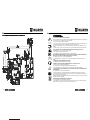
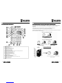
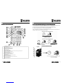
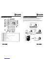
5.1 COMANDI PANNELLO FRONTALE/REGOLAZIONI INTERNE
5.1 COMANDI PANNELLO FRONTALE/REGOLAZIONI INTERNE5.1 COMANDI PANNELLO FRONTALE/REGOLAZIONI INTERNE
5.1 COMANDI PANNELLO FRONTALE/REGOLAZIONI INTERNE
1
2
3
4
5
6
7
8
9
10
11
12
13
14
15
16
17
18
19
Led segnalazione allarme termico
Led segnalazione abilitazione alla saldatura
Led segnalazione macchina sotto tensione di linea
Led segnalazione saldatura elettrodo
Led segnalazione saldatura TIG lift
Led segnalazione saldatura Mig 2t
Led segnalazione saldatura Mig 4t
Pulsante selezione modalità di saldatura
Attacco euro centralizzato
Boccola di uscita negativa.
Boccola di uscita positiva.
Potenziometro di regolazione corrente/velocità filo
Potenziometro di regolazione tensione/spessore materiale
Led selezione sinergia filo 0.8 / 1.0
Pulsante selezione modalità sinergica
Vite Regolazione post-gas
Vite Regolazione Burn back
Pulsante per avanzamento filo
Pulsante per spurgo gas
1
2
3
4
5
6
7
8
9
10 11
12
13
14
15
19
18
17
16

8
I
1
2
3
4
5
6
7
8
9
10
11
12
13
14
15
16
17
18
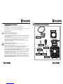
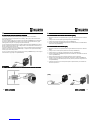
a) IDENTIFICAZIONE
Nome, indirizzo del costruttore
Tipo della saldatrice
Identificazione riferita al numero di serie
Simbolo del tipo di saldatrice
Riferimento alla normativa di costruzione
b) USCITA DELLA SALDATURA
Simbolo del processo di saldatura
Simbolo per le saldatrici idonee ad operare in ambiente a rischio accresciuto di scossa elettrica.
Simbolo della corrente di saldatura
Tensione assegnata a vuoto (tensione media)
Gamma della corrente di saldatura
Valori del ciclo di intermittenza (su 10 minuti)
Valori della corrente assegnata di saldatura
Valori della tensione convenzionale a carico
c) ALIMENTAZIONE
Simbolo per l’alimentazione (numero fasi e frequenza)
Tensione assegnata di alimentazione
Massima corrente di alimentazione
Massima corrente efficace di alimentazione (identifica il fusibile di linea)
d) ALTRE CARATTERISTICHE
Grado di protezione (IP 22).
5.2
5.2 5.2
5.2 DESCRIZIONE
DESCRIZIONEDESCRIZIONE
DESCRIZIONE
TARGA
TARGATARGA
TARGA
DATI
DATIDATI
DATI
1
2
4
6
7
8
14
9
18 15 16 17
13
12
11
10
5
3
41
GB
6.3 INTERMITTENCE CY
6.3 INTERMITTENCE CY6.3 INTERMITTENCE CY
6.3 INTERMITTENCE CYCLE (
CLE (CLE (
CLE (DC) AND EXCESS TEMPERA
DC) AND EXCESS TEMPERADC) AND EXCESS TEMPERA
DC) AND EXCESS TEMPERATURE
TURETURE
TURE
The intermittence cycle is the percentage of use of the welding machine in 10 minutes which the operator
must respect so as to ensure that the generator does not stop supply due to blocking for excess
temperature.
If the machine goes into excess temperature the yellow led (n.1 Section 5.1) lights up.
It is therefore necessary to wait about 10 minutes before resuming welding.
The block of supply is reversible, to avoid further interventions of the protection the current or the work time
must be reduced after resuming welding.
EXCESS TEMPERATURE
Wait 10 minutes

40
GB
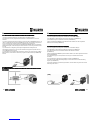
6.0 FIGURES
6.0 FIGURES6.0 FIGURES
6.0 FIGURES
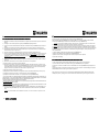
6.1
6.1 6.1
6.1 REAR AND SIDE DISTANCES TO BE MAINTAINED DURING WELDING
REAR AND SIDE DISTANCES TO BE MAINTAINED DURING WELDINGREAR AND SIDE DISTANCES TO BE MAINTAINED DURING WELDING
REAR AND SIDE DISTANCES TO BE MAINTAINED DURING WELDING
5.7 PREPARING FOR MIG SYNERGIC WELDING
5.7 PREPARING FOR MIG SYNERGIC WELDING5.7 PREPARING FOR MIG SYNERGIC WELDING
5.7 PREPARING FOR MIG SYNERGIC WELDING
1) Respect the indications given previously concerning primary connection and installation.
2) The welding machine is also predisposed for the welding in MIG synergic mode with thread steel /
carbon from 0.6 and 0.8.
3) To plan the welding in MIG synergic to press the Auto Set button (n.15 Section 5.1), the led selection
mig synergic mode (n.14 Section 5.1), it ignites red color (synergic mode planned thread 0.6), again
pressing ignites the led green color (synergic mode planned thread 0.8).
4) To this point through the potenziometer of regulation material thickness (n.13 Section 5.1) to plan the
thickness of material that is desired to settle, making reference to the red staircase for thread from 0.6 or
the green staircase for the thread from 0.8.
5) There is the possibility to effect an adjustment of the + /-20% of the speed through the potenziometer of
regulation of the speed of the thread (n.12 Section 5.1), in comparison to the optimal value autosetting
from the program of the welding machine.
6) To go out of the mig synergic mode to press the Auto Set button (n.15 Section 5.1) up to the turning off
of the led selection mig synergic mode (n.14 Section 5.1) .
9
I
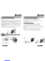
5.3 DISPOSIZIONE SALDATURA ELETTRODO (MMA)
5.3 DISPOSIZIONE SALDATURA ELETTRODO (MMA) 5.3 DISPOSIZIONE SALDATURA ELETTRODO (MMA)
5.3 DISPOSIZIONE SALDATURA ELETTRODO (MMA)
1) Rispettare le indicazioni fornite precedentemente a riguardo dell’ allacciamento primario e dell’instal-
lazione.
2) Collegare il cavo massa alla presa negativa del generatore (n.10 Section 5.1)
3) Collegare la pinza porta elettrodi alla presa positiva (n.11 Section 5.1).
4) Tramite il pulsante MODE (n.8 Section 5.1) selezionare la modalità elettrodo, led modalità elettrodo
selezionata acceso (n.4 Section 5.1).
5.4 DISPOSIZIONE SALDATURA (TIG
5.4 DISPOSIZIONE SALDATURA (TIG5.4 DISPOSIZIONE SALDATURA (TIG
5.4 DISPOSIZIONE SALDATURA (TIG
)
) )
)
1) Rispettare le indicazioni fornite precedentemente a riguardo dell’allacciamento primario e dell’instal-
lazione.
2) Collegare il cavo di massa alla presa positiva della macchina (n.11 Section 5.1).
3) Collegare l’attacco torcia alla presa centralizzata della macchina (n.9 Section 5.1).
4) Tramite il pulsante MODE (n.8 Section 5.1) selezionare la modalità TIG, led modalità TIG seleziona-
ta acceso (n.5 Section 5.1).
5) Allacciare la bombola del gas (Argon) all’apposito dispositivo sul retro del generatore.
6) Impostare la corrente di saldatura con il potenziometro di regolazione corrente (n.12 Section 5.1).
Impostare il tempo di SLOPE-DOWN (rampa di discesa), tramite il potenziometro di regolazione fun-
zioni (n.13 Section 5.1).
7) Controllare la posizione del cavo cambio polarità aprendo lo sportello laterale: per la saldatura TIG
deve essere in posizione “-”.
(MMA) (TIG)

10
I
5.5 DISPOSIZIONE SALDATURA
5.5 DISPOSIZIONE SALDATURA 5.5 DISPOSIZIONE SALDATURA
5.5 DISPOSIZIONE SALDATURA MIG
MIGMIG
MIG CON GAS
CON GAS CON GAS
CON GAS
1) Rispettare le indicazioni fornite precedentemente a riguardo dell’ allacciamento primario e dell’instal-
lazione.
2) Collegare il cavo massa alla presa negativa (n.10 Section 5.1)del generatore.
3) Inserire il connettore della torcia MIG nella presa centralizzata euro (n.10 Section 5.1) e avvitare la
ghiera
4) Collegare la bombola del gas (MIX) all‘apposito attacco sul pannello posteriore della macchina.
5) Controllare la posizione del cavo cambio polarità aprendo lo sportello laterale: per la saldatura MIG
CON GAS deve essere in posizione “+”.
6) Caricare il filo aprendo lo sportello laterale e inserendo la matassa nell’apposito perno.
7) Inserire il filo nel trainafilo facendolo aderire alla gola del rullo (ATTENZIONE: il rullo ha due gole per-
ché girandolo è possibile usarlo per un’altra misura di filo). Quando si cambia la sezione del filo è
necessario cambiare: rulli e tubetto portacorrente (è la parte terminale della torcia da cui si vede
spuntare il filo).
8) Svitare la terminazione esterna della torcia (ugello) e il tubetto portacorrente per facilitare il passag-
gio del filo.
9) Srotolare il cavo della torcia in modo da far fare al filo meno curve possibile.
10) Inserire la spina in una presa di corrente adeguata.
11) Chiudere il rullo pressore, accendere la macchina portando l’interruttore di linea in posizione “ON”,
premere il pulsante avanzamento filo ((n.3 Section 5.1)per far girare il motore del traino fino alla fuo-
riuscita del filo dalla torcia (tenere chiuso lo sportello laterale mentre si compie questa operazione).
Spegnere la macchina portando l’interruttore di linea in posizione “OFF”.
12) Riavvitare il tubetto portacorrente e l'ugello.
13) Regolare la frizione del trainafilo (una regolazione più accurata sarà possibile dopo alcune prove).
14) Impostare il valore del post-gas con il potenziometro a vite (n.1 Section 5.2).
15) Impostare il valore dello burn-back* con il potenziometro a vite (n.2 Section 5.2).
*: Il burn-back consiste in un ritardo dello spegnimento dell’arco di saldatura rispetto all‘arresto del trainafilo. Con
il potenziometro a “0” si ha l’arresto del trainafilo contemporaneamente allo spegnimento dell’arco. Per correnti di
saldatura elevate si consiglia di immettere il valore “0” (effettuare qualche prova).
Una errata regolazione di questo parametro può comportare:
- Burn-back troppo basso: a fine saldatura si ha uno spezzone troppo lungo di filo che fuoriesce dalla torcia; risul-
ta così difficoltoso riprendere a saldare.
- Burn-back troppo alto: a fine saldatura si ha uno spezzone troppo corto di filo che fuoriesce dalla torcia e in casi
estremi può avvenire l’incollaggio tra il filo e il tubetto portacorrente.
16) Tramite il pulsante MODE (n.8 Section 5.1) selezionare la modalità MIG 2t, led modalità MIG 2t se-
lezionata acceso (n.6 Section 5.1) o MIG 4t led modalità MIG 4t selezionata acceso (n.7 Section
5.1)
2 tempi: in questa modalità l’arco di saldatura si innesca, con il filo a contatto con il pezzo, nel mo-
39
GB
Set the burn-back* value with the screw potentiometer (n.2 Section 5.2)
With the MODE button (n.8 Section 5.1) to select the MIG 2t or 4t mode, led MIG 2t mode selected
turned on (n.6 Section 5.1), led MIG 4t mode selected turned on (n.7 Section 5.1)
2 times: in this mode the welding arc lights, with the wire in contact with the piece, the moment the
torch button is pressed and it goes out the moment the button is released.
4 times: in this mode gas comes out (pre-gas) the moment the torch button is pressed, the welding
arc lights, with the wire in contact with the piece, the moment the button is released; when it is pressed
again, the arc goes out and more gas comes out to cool the piece (the gas comes out the whole time that
the button is pressed); when the button is released the post-gas time begins, as set previously with the
screw potentiometer.
17) Set the welding voltage with the potentiometer (n.13 Section 5.1)
18) Set the wire speed with the potentiometer (n.12 Section 5.1)
19) Switch on the machine, turning the switch on the back panel to “ON” position.
20) Proceed with welding.
5.6 PREPARING FOR MIG WELDING WITHOUT GAS
5.6 PREPARING FOR MIG WELDING WITHOUT GAS5.6 PREPARING FOR MIG WELDING WITHOUT GAS
5.6 PREPARING FOR MIG WELDING WITHOUT GAS
To use a special cored wire that allows welding without the use of gas, proceed as follows:
1) Connect the earth cable to the positive socket (+) (n.11 Section 5.1) of the generator.
2) Insert the connector of the MIG torch in the centralised euro socket (n.9 Section 5.1) and tighten the
ring nut.
3) Check the position of the polarity changing cable, opening the side door: for MIG welding with special
CORED WIRE without the use of gas it must be in position "-".
Now proceed as in the instructions in the paragraph "PREPARING FOR MIG WELDING WITH GAS",
starting from point 6, ignoring point 14 and of course all the references to gas coming out of the torch.

38
GB
5.5 PREPARING FOR MIG WELDING WITH GAS
5.5 PREPARING FOR MIG WELDING WITH GAS5.5 PREPARING FOR MIG WELDING WITH GAS
5.5 PREPARING FOR MIG WELDING WITH GAS
1) Respect the indications given previously concerning primary connection and installation.
2) Connect the earth cable to the negative socket (n.10 Section 5.1) of the generator.
3) Insert the connector of the MIG torch in the centralised euro socket (n.9 Section 5.1) and tighten the
ring nut.
4) Connect the gas cylinder (MIX) to the coupling provided on the rear panel of the machine.
5) Check the position of the polarity changing cable, opening the side door: for MIG welding WITH GAS it
must be in position “+”.
6) Load the wire, opening the side door and ifitting the bobbin on the reel provided.
7) Insert the wire in the wire feeder, making it adhere to the race of the roller (ATTENTION: the roller has
two races because by turning it over it can be used for another size of wire). When changing the section of
the wire it is necessary to change the rollers and the current supply pipe (that is the end part of the torch
from which you can see the wire protruding).
8) Unscrew the outside end of the torch (nozzle) and the current supply pipe to facilitate the passage of the
wire.
9) Unwind the torch cable so that the wire makes the least possible number of curves .
10) Insert the plug in a suitable power socket.
11) Close the pressing roller, switch on the machine turning the line switch to “ON” position, press the wire
advance button (n.3 Section 5.2) to make the feeding motor run until the wire comes out of the torch (keep
the side door closed while performing this operation). Switch off the machine, turning the line switch to
“OFF” position.
12) Screw the current supply pipe and the nozzle back on.
13) Regulate the friction of the wire feeder (a more accurate regulation will be possible after a few tests).
14) Set the post-gas value with the screw potentiometer (n.1 Section 5.2)
15) Set the burn-back* value with the screw potentiometer (n.2 Section 5.2)
16) With the MODE button (n.8 Section 5.1) to select the MIG 2t or 4t mode, led MIG 2t mode selected
turned on (n.6 Section 5.1) led MIG 4t mode selected turned on (n.7 Section 5.2)
*: The burn-back is a delay in switching off the welding arc with respect to the stopping of the wire feeding device.
With the potentiometer set at “0” the wire feeder stops at the same time as when the arc goes out . For high
welding currents it is advisable to set the value “0” (make a few tests).
Incorrect regulation of this parameter may lead to:
- Burn-back too low: at the end of welding, the piece of wire protruding from the torch is too long; it is
therefore difficult to resume welding.
- Burn-back too high: at the end of welding, the piece of wire protruding from the torch is too short and in
extreme cases the wire may stick to the current supply pipe.
*: The burn-back is a delay in switching off the welding arc with respect to the stopping of the wire feeding device.
With the potentiometer set at “0” the wire feeder stops at the same time as when the arc goes out . For high
welding currents it is advisable to set the value “0” (make a few tests).
11
I
mento in cui si preme il pulsante torcia e si spegne nel momento in cui lo si rilascia.
4 tempi: in questa modalità si ha la fuoriuscita di gas (pre-gas) nel momento in cui si preme il pulsan-
te torcia, l’arco di saldatura si innesca, con il filo a contatto con il pezzo, nel momento in cui lo si rilascia;
premendolo ancora si ha lo spegnimento dell’arco e un’ulteriore fuoriuscita di gas per raffreddare il pezzo
(il gas esce per tutto il tempo in cui rimane premuto il pulsante); al momento del rilascio del pulsante ini-
zia il post-gas precedentemente impostato tramite il potenziometro a vite .
17) Impostare la tensione di saldatura con il potenziometro (n.13 Section 5.1).
18) Impostare la velocità del filo con il potenziometro (n.12 Section 5.1).
19) Accendere la macchina posizionando l’interruttore posto sul pannello posteriore in posizione “ON” .
20) Procedere con la saldatura.
5.6 DISPOSIZIONE SALDATURA
5.6 DISPOSIZIONE SALDATURA 5.6 DISPOSIZIONE SALDATURA
5.6 DISPOSIZIONE SALDATURA MIG
MIGMIG
MIG
SENZA
SENZASENZA
SENZA GAS
GAS GAS
GAS
Per l'impiego di un filo animato speciale che prevede una saldatura senza impiego di gas, procedere in
questo modo:
1) Collegare il cavo massa alla presa positiva (+) (n.11 Section 5.1) del generatore.
2) Inserire il connettore della torcia MIG nella presa centralizzata euro (n.9 Section 5.1) e avvitare la
ghiera
3) Controllare la posizione del cavo cambio polarità aprendo lo sportello laterale: per la saldatura MIG
con FILO ANIMATO speciale senza impiego di gas deve essere in posizione "-".
Procedere ora come da istruzioni del paragrafo "DISPOSIZIONE SALDATURA MIG CON GAS" partendo
dal punto 6, ignorando il punto 14 e ovviamente tutti i riferimenti alla fuoriuscita di gas dalla torcia.

12
I
6.0 FIGURE
6.0 FIGURE6.0 FIGURE
6.0 FIGURE
6.1 DISTANZE POSTERIORI E LATERALI DA MANTENERE DURANTE LA
6.1 DISTANZE POSTERIORI E LATERALI DA MANTENERE DURANTE LA 6.1 DISTANZE POSTERIORI E LATERALI DA MANTENERE DURANTE LA
6.1 DISTANZE POSTERIORI E LATERALI DA MANTENERE DURANTE LA
SALDATURA
SALDATURASALDATURA
SALDATURA
5.7 DISPOSIZIONE SALDATURA
5.7 DISPOSIZIONE SALDATURA 5.7 DISPOSIZIONE SALDATURA
5.7 DISPOSIZIONE SALDATURA MIG
MIGMIG
MIG SINERGICO
SINERGICO SINERGICO
SINERGICO
1) Rispettare le indicazioni fornite precedentemente a riguardo dell’ allacciamento primario e dell’installa-
zione.
2) La macchina è predisposta anche per la saldatura in modalità MIG sinergico con filo acciaio/carbonio
da 0.6 e 0.8.
3) Per impostare la saldatura in modalità sinergica premere il pulsante AUTO SET (n.15Section 5.1) , il
led selezione modalità mig sinergico (n.14 Section 5.1) si accende color rosso (sinergia impostata filo
0.6), premendo nuovamente si accende il led color verde (sinergia impostata filo 0.8).
4) A questo punto tramite il potenziometro di regolazione spessore materiale (n.13 Section 5.1) imposta-
re lo spessore di materiale che si desidera saldare, facendo riferimento alla scala rossa per filo da 0.6 o
la scala verde per il filo da 0.8.
5) C’è la possibilità di effettuare un aggiustamento del +/-20% della velocità tramite il potenziometro di
regolazione della velocità del filo (n.12 Section 5.1), rispetto al valore ottimale reimpostato dal program-
ma della macchina.
6) Per uscire dalla modalità mig sinergico premere il pulsante AUTO SET (n.15 Section 5.1) fino allo
spegnimento del led selezione modalità mig sinergico (n.14 Section 5.1).
37
GB
5.3 PREPARING FOR ELECTRODE WELDING (MMA)
5.3 PREPARING FOR ELECTRODE WELDING (MMA) 5.3 PREPARING FOR ELECTRODE WELDING (MMA)
5.3 PREPARING FOR ELECTRODE WELDING (MMA)
1) Respect the indications given previously concerning primary connection and installation.
2) Connect the earth cable to the negative socket of the generator (n.10 Section 5.1)
3) Connect the electrode holder to the positive socket (n.11 Section 5.1)
4) With the MODE button (n.8 Section 5.1) to select the electrode mode, led electrode mode selected
turned on (n.4 Section 5.1)
5.4 PREPARING FOR WELDING (TIG)
5.4 PREPARING FOR WELDING (TIG) 5.4 PREPARING FOR WELDING (TIG)
5.4 PREPARING FOR WELDING (TIG)
1) Respect the indications given previously concerning primary connection and installation.
2) Connect the earth cable to the positive socket of the machine (n.11 Section 5.1)
3) Connect the torch coupling to the centralised euro socket of the machine (n.9 Section 5.1)
3) Check the position of the polarity changing cable, opening the side door: for TIG welding it must be in
position "-".
4) With the MODE button (n.8 Section 5.1) to select the TIG mode, led TIG mode selected turned on (n.5
Section 5.1)
5) Connect the gas cylinder (Argon) to the device provided on the rear of the generator.
6) Set the welding current with the current regulating potentiometer (n.12 Section 5.1)
7) Set the SLOPE-DOWN time with the function regulating potentiometer (n.13 Section 5.1)
(MMA) (TIG)

36
GB
1
2
3
4
5
6
7
8
9
10
11
12
13
14
15
16
17
18
a) IDENTIFICATION
Name, address of the manufacturer
Type of welding machine
Identification with reference to serial number
Symbol of the type of welding machine
Reference to the construction standards
b) WELDING OUTPUT
Symbol of the welding process
Symbol for welding machines suitable for working in an environment with a high risk of electric shock.
Symbol of the welding current
Assigned no-load voltage (mean voltage)
Range of the welding current
Values of the intermittence cycle (in 10 minutes)
Values of the assigned welding current
Values of the conventional loaded voltage
c) POWER SUPPLY
Power supply symbol (number of phases and frequency)
Assigned power supply voltage
Maximum power supply current
Maximum effective power supply current (identifies the line fuse)
d) OTHER CHARACTERISTICS
Degree of protection (IP 22).
5.2
5.2 5.2
5.2 DATA PLATE DESCRIPTI
DATA PLATE DESCRIPTIDATA PLATE DESCRIPTI
DATA PLATE DESCRIPTION
ON ON
ON
1
2
4
6
7
8
14
9
18 15 16 17
13
12
11
10
5
3
13
I
6.2
6.2 6.2
6.2 CICLO
CICLOCICLO
CICLO
DI
DIDI
DI
INTERMITTENZA
INTERMITTENZAINTERMITTENZA
INTERMITTENZA (DC)
(DC) (DC)
(DC) E
EE
E
SOVRATEMPERATURA
SOVRATEMPERATURASOVRATEMPERATURA
SOVRATEMPERATURA
Il ciclo di intermittenza è la percentuale di utilizzo su 10 minuti che l’ operatore deve rispettare, per evita-
re che il generatore smetta di erogare per intervento del blocco per sovratemperatura.
Se la macchina si blocca per sovratemperatura il led giallo (n.1 Section 5.1) si accende.
E’ necessario quindi attendere circa 10 minuti per riprendere a saldare.
Il blocco di erogazione è reversibile, per evitare ulteriori interventi della protezione occorre ridurre l’ am-
peraggio o il tempo di lavoro dopo aver ripreso a saldare.

14
I
7.0 INCONVENIENTI DI SALDATURA E FUNZIONAMENTO
7.0 INCONVENIENTI DI SALDATURA E FUNZIONAMENTO7.0 INCONVENIENTI DI SALDATURA E FUNZIONAMENTO
7.0 INCONVENIENTI DI SALDATURA E FUNZIONAMENTO
7.1 POSSIBILI DIFETTI IN SALDATURA
7.1 POSSIBILI DIFETTI IN SALDATURA7.1 POSSIBILI DIFETTI IN SALDATURA
7.1 POSSIBILI DIFETTI IN SALDATURA
DIFETTO CAUSE CONSIGLI
CRICCHE
Elettrodo acido su acciaio ad alto tenore di
zolfo.
Eccessive oscillazioni dell’elettrodo.
Distanza troppo grande tra i pezzi da sal-
dare.
Pezzo in saldatura freddo.
Usare elettrodo basico.
Avvicinare i lembi da saldare.
Avanzare lentamente all’inizio.
Diminuire la corrente di saldatura.
POROSITÀ
Materiale da saldare sporco (es. olio, verni-
ce, ruggine, ossidi).
Corrente insufficiente.
Pulire i pezzi prima di saldare è principio
fondamentale per ottenere buoni cordoni di
saldatura.
SCARSA PENETRAZIONE
Corrente bassa.
Velocità saldatura elevata.
Polarità invertita.
Elettrodo inclinato in posizione opposta al
suo movimento.
Curare la regolazione dei parametri opera-
tivi e migliorare la preparazione dei pezzi
da saldare.
SPRUZZI ELEVATI
Inclinazione elettrodo eccessiva. Effettuare le opportune correzioni.
DIFETTI Dl PROFILI
Parametri saldatura non corretti.
Velocità passata non legata alle esigenze
dei parametri operativi.
Inclinazione dell’elettrodo non costante
durante la saldatura.
Rispettare i principi basilari e generali di
saldatura.
INSTABILITÀ D’ARCO
Corrente insufficiente. Controllare lo stato dell’elettrodo e il colle-
gamento del cavo di massa.
L’ELETTRODO FONDE OBLIQUA-
MENTE
Elettrodo con anima non centrata.
Fenomeno del soffio magnetico.
Sostituire l’elettrodo.
Collegare due cavi di massa ai lati opposti
del pezzo da saldare.
7.2 POSSIBILI INCONVENIENTI DI FUNZIONAMENTO
7.2 POSSIBILI INCONVENIENTI DI FUNZIONAMENTO7.2 POSSIBILI INCONVENIENTI DI FUNZIONAMENTO
7.2 POSSIBILI INCONVENIENTI DI FUNZIONAMENTO
INCONVENIENTE CAUSE RIMEDIO
MANCATA ACCENSIONE
-Allacciamento primario non corretto.
-Scheda inverter difettosa.
-Controllare il collegamento primario.
-Rivolgersi al Vs. centro assistenza.
NON SI HA TENSIONE IN U-
SCITA
-Macchina surriscaldata (led giallo acce-
so).
-Scheda inverter difettosa.
-Tensione di alimentazione primaria bas-
sa.
-Aspettare il ripristino termico.
-Rivolgersi al Vs. centro assistenza.
CORRENTE IN USCITA NON
CORRETTA
-Potenziometro di regolazione difettoso.
-Tensione di alimentazione primaria bas-
sa.
-Rivolgersi al Vs. centro assistenza.
-Controllare la rete di distribuzione.
35
GB
5.0
5.0 5.0
5.0 SETTING UP
SETTING UPSETTING UP
SETTING UP
5.1
5.1 5.1
5.1 CONTROLS ON THE FRONT PANEL/INTERNAL REGULATIONS
CONTROLS ON THE FRONT PANEL/INTERNAL REGULATIONSCONTROLS ON THE FRONT PANEL/INTERNAL REGULATIONS
CONTROLS ON THE FRONT PANEL/INTERNAL REGULATIONS
1
2
3
4
5
6
7
8
9
10
11
12
13
14
15
16
17
18
19
Thermal alarm indicating led
Machine enable indicating led
Welding live indicating led
MMA mode indicating led
TIG mode indicating led
MIG 2t indicating led
MIG 4t indicating led
Welding type selection button
Centralised euro coupling
Negative output bush
Positive output bush
Potentiometer for regulating welding current (MMA-TIG) and wire speed (MIG)
Potentiometer for regulating output voltage (MIG) and thikness material (synergic MIG)
Synergic mode 0,6-0,8 indicating led
Synergic mode selection button
Post-Gas Regolation crew
Burn Back Regolation crew
Wire advance Button
Gas Purge Button
19
18
17
16
1
2
3
4
5
6
7
8
9
10 11
12
13
14
15

34
GB
- Avoid impacts, rubbing, and - absolutely - exposure to dripping water, excessive heat sources, or any
abnormal situations.
MAINS VOLTAGE
The generator works at mains voltages differing by 15% from the rated mains value (rated voltage 230V,
minimum voltage 185V, maximum voltage 275V).
SUPPLY BY MOTOR GENERATOR
The generator is designed to work supplied by generating sets.
It is important for the generating set to satisfy the conditions listed in (Section 2.0)
It is recommended not to use this machine with generating sets that do not respect these conditions
because it could be damaged.
Warning: Turn on the machine only after the motogenerator state initiated
CONNECTION
- Before making the electrical connections between the current generator and the line switch, ensure that
the switch is turned off.
- The distribution panel must comply with the regulations in force in the country of use .
- The mains system must be of the industrial type.
- The multipolar cable is provided with a type G32 plug (Schuko) complying with standard UNI 47 166/68.
Provide a special socket, model SCHUKO 16A , which can receive leads with a section of 2.5mm².
- For longer connecting cables, increase the lead section as required.
- Upstream, the mains socket must have a suitable switch provided with delayed fuses.
4.2 EARTHING
4.2 EARTHING4.2 EARTHING
4.2 EARTHING
- To ensure user protection the welding machine must absolutely be correctly connected to the earth
system (INTERNATIONAL SAFETY REGULATIONS).
- It is indispensable to provide good earthing by means of the yellow-green lead in the power cable, in
order to avoid discharges due to accidental contacts with earthed objects.
The chassis (which is conductive) is electrically connected with the earth lead; if the equipment is not
suitably connected to earth it may cause electric shocks which are dangerous for the user.
15
D

16
D
ALLGEMEINES INHALTSVERZEICHNIS
ALLGEMEINES INHALTSVERZEICHNIS ALLGEMEINES INHALTSVERZEICHNIS
ALLGEMEINES INHALTSVERZEICHNIS
1.0 SICHERHEIT
1.1 HINWEISE
1.2 SICHERHEITSVORSCHRIFTEN
2.0 SPEZIFIKATIONEN ELEKTRISCHE MERKMALE
3.0 REKLAMATIONEN
4.0 ANSCHLUSS
4.1 PRIMÄRANSCHLUSS UND SCHALTUNG
4.2 ERDUNG
5.0 INBETRIEBNAHME
5.1 SCHALTELEMENTE DES FRONTPANEELS/INNERES BEDIENPANEEL
5.2 BESCHREIBUNG DES TYPENSCHILDS
5.3 ANLEITUNG ZUM ELEKTRODENSCHWEISSEN (MMA)
5.4 ANLEITUNG ZUM WIG-SCHWEISSEN
5.5 ANLEITUNGEN ZUM MIG-SCHWEISSEN MIT GAS
5.6 ANLEITUNGEN ZUM MIG-SCHWEISSEN OHNE GAS
5.7 ANLEITUNG ZUM SYNERGETISCHEN MIG-SCHWEISSEN
6.0 ABBILDUNGEN
6.1 BEIM SCHWEISSEN RÜCKSEITIG UND SEITLICH ZU BEACHTENDE ABSTÄNDE, UM SCHWEISS– UND
FUNKTIONSSTÖRUNGEN ZU VERMEIDEN
6.2 AUSSETZZYKLUS UND ÜBERTEMPERATUR
7.0 SCHWEISS– UND BETRIEBSSTÖRUNGEN
7.1 MÖGLICHE SCHWEISSMÄNGEL
7.2 MÖGLICHE BETRIEBSSTÖRUNGEN
8.0 BESTANDTEILLISTE UND DETAILANSICHTEN (ENGLISH)
8.1 BESTANDTEILLISTE (ENGLISH)
8.2 DETAILANSICHT GENERATOR (ENGLISH)
8.3 BESTANDTEILLISTE WIRE FEEDER (ENGLISH)
9.0 ALLGEMEINER SCHALTPLAN (ENGLISH)
10.0 STROM-UND BETRIEBSSTORUNGEN (ENGLISH)
33
GB
2.0
2.0 2.0
2.0 GENERAL/
GENERAL/GENERAL/
GENERAL/ELECTRICAL CHARACTER
ELECTRICAL CHARACTERELECTRICAL CHARACTER
ELECTRICAL CHARACTERISTICS
ISTICSISTICS
ISTICS
The date are determined at an environment temperature of 40°C by Simulation.
N.B. The Generator is not Suitable for defrosting pipes.
3.0 COMPLAINTS
3.0 COMPLAINTS3.0 COMPLAINTS
3.0 COMPLAINTS
Complaints for damage during transport: If your equipment is damaged during transit you must present a
claim to the carrier.
Complaints for faulty goods: All the equipment shipped by WURTH is subjected to strict quality control.
However, if your equipment does not work properly, consult the TROUBLESHOOTING section of this
manual. If the fault persists, consult your authorised dealer.
4.0
4.0 4.0
4.0 CONNECTION
CONNECTIONCONNECTION
CONNECTION
4.1 PRIMARY AND MAIN
4.1 PRIMARY AND MAIN4.1 PRIMARY AND MAIN
4.1 PRIMARY AND MAINS CONNECTION
S CONNECTIONS CONNECTION
S CONNECTION
INSTALLATION
WARNING: This Class A equipment is not intended for use in residential locations where the electrical
power is provided by the public low-voltage supply system.
There may be potential difficulties in ensuring electromagnetic compatibility in those locations, due to
conducted as well as radiated disturbances.
This equipment does not comply with IEC 61000-3-12. If it is connected to a public pow voltage system, it
is the responsibility of the installer or user of the equipment to ensure, by consultation with the distribution
network operator if necessary, that the equipment may be connected.
The good operation of the generator is ensured by correct installation; you must therefore proceed as
follows:
- Position the machine in such a way that there is no obstacle to the air circulation ensured by the internal
fan (the internal components require suitable cooling) (Section 6.3)
- Ensure that the fan does not send deposits or dust into the machine.
Supply voltage
Phases
Frequency
Rated power DC 40%
Rated power DC 60%
No-load voltage
Current regulation range
Welding current DC 40%
Welding current DC 60%
Welding current DC 100%
Length
Width
Height
Weight
V
-
Hz
KVA
KVA
V
A
A
A
A
mm
mm
mm
Kg
GENERATOR
ELECTRODE
230
1
50/60
6,5
5,7
58
25 - 150
150
130
105
230
1
50/60
5
3.8
58
8 - 160
160
130
105
TIG
230
1
50/60
5.7
4.5
14.7-22
35 - 160
160
135
105
MIG
500
190
400
19

32
GB
1.2 SAFETY INSTRUCTI
1.2 SAFETY INSTRUCTI1.2 SAFETY INSTRUCTI
1.2 SAFETY INSTRUCTIONS
ONS ONS
ONS
PREVENTION OF BURNS
To protect your eyes and skin from burns and ultraviolet rays:
- wear dark glasses. Wear suitable clothing, gloves and footwear.
- use masks with closed sides, having lenses and protective glass according to standards
(degree of protection DIN 10).
- warn people in the vicinity not to look directly at the arc.
PREVENTION OF FIRE
Welding produces splashes of molten metal.
Take the following precautions to prevent fire:
- ensure that there is an extinguisher in the welding area.
- remove all inflammable material from the immediate vicinity of the welding area.
- cool the welded material or let it cool before touching it or putting it in contact with combustible
material.
- never use the machine for welding containers of potentially inflammable material. These
containers must be completely cleaned before they are welded.
- ventilate the potentially inflammable area before using the machine.
- do not use the machine in atmospheres containing high concentrations of powders,
inflammable gases or combustible vapours.
PREVENTION OF ELECTRIC SHOCK
Take the following precautions when working with a current generator:
- keep yourself and your clothes clean.
- do not be in contact with damp or wet parts when working with the generator.
- maintain suitable insulation against electric shock. If the operator has to work in a damp
environment, he must take extreme care and wear insulating footwear and gloves.
- check the machine power cable frequently: it must be free from damage to the insulation.
BARE CABLES ARE DANGEROUS. Do not use the machine if the power cable is damaged; it
must be replaced immediately.
- if it is necessary to open the machine, first disconnect the power supply.
Wait 5 minutes to allow the capacitors to discharge. Failure to take this precaution may expose
the operator to dangerous risks of electric shock.
- never work with the welding machine if the protective cover is not in place.
- ensure that the earth connection of the power cable is perfectly efficient.
This generator has been designed for use in a professional and industrial environment. For
other types of application contact the manufacturer. If electromagnetic disturbances are
found it is the responsibility of the machine user to solve the problem with the technical
assistance of the manufacturer.
17
D
1.0 SICHERHEIT
1.0 SICHERHEIT1.0 SICHERHEIT
1.0 SICHERHEIT
1.1 HINWEISE
1.1 HINWEISE1.1 HINWEISE
1.1 HINWEISE
STROMSCHLÄGE KÖNNEN TÖDLICHE FOLGEN HABEN
- Vor dem Eingreifen auf den Generator die Maschine vom Stromnetz abstecken.
- Niemals mit defekten Kabelummantelungen arbeiten.
- Blank liegende elektrische Teile nicht berühren.
- Sich vor dem Anschließen der Maschine an das Stromnetz überzeugen, dass alle
Deckpaneele des Stromgenerators richtig und gut befestigt sind.
- Achten Sie darauf, sich selbst vom Arbeitsbett und Boden (Ground) zu isolieren: isolierendes
Schuhwerk und Handschuhe tragen.
- Handschuhe, Schuhe, Bekleidungsstücke, Arbeitsbereich und die Gerätschaft stets sauber
und trocken halten.
SÄMTLICHE UNTER DRUCK STEHENDE BEHÄLTER LAUFEN BEIM SCHWEISSEN
GEFAHR ZU EXPLODIEREN.
Beim Arbeiten mit einem Stromgenerator ist Folgendes zu beachten:
- niemals unter Druck stehende Behälter schweißen;
- niemals in Umgebungen schweißen, die mit explosivem Staub oder mit explosiven Dämpfen
verseucht sind.
DIE VOM LICHTBOGEN ERZEUGTEN STRAHLUNGEN KÖNNEN ZU AUGENSCHÄDEN
UND HAUTVERBRENNUNGEN FÜHREN.
- Die Augen und den Körper entsprechend schützen.
- Kontaktlinsenträger müssen sich unbedingt mit entsprechenden Brillen und Masken
schützen.
DER LÄRM KANN ZU GEHÖRSCHÄDEN FÜHREN.
- Sich entsprechend schützen.
RAUCH UND GASE KÖNNEN FÜR IHRE GESUNDHEIT SCHÄDLICH SEIN.
- Das Haupt außerhalb der Reichweite des Rauchs halten.
- Für eine entsprechende Belüftung des Arbeitsbereichs sorgen.
- Bei ungenügender Belüftung für eine von unten ansaugende Sauganlage sorgen.
HITZE, FLÜSSIGE METALLSPRITZER UND FUNKEN KÖNNEN BRANDURSACHE SEIN.
- Nie in der Nähe von entflammbaren Materialien schweißen.
- Es unbedingt vermeiden, Brennstoffe, wie Feuerzeuge oder Streichhölzer mit sich zu tragen.
- Der Lichtbogen kann Verbrennungen verursachen. Die Elektrodenspitze fern vom eigenen
Körper und dem anderer Personen halten.
Trägern von elektrischen Herzschrittmachern (PACE MAKERS) ist es strengstens untersagt,
sich der Maschine zu nähern bzw. diese zu bedienen.
HINWEIS ZUR UNSICHEREN POSITIONIERUNG
- Ein Herunterfallen des Generators kann Unfälle verursachen.
- Nehmen Sie daher den unsicher positionierten Generator niemals in Betrieb oder verlegen
Sie ihn. Stellen Sie den Generator niemals auf Ebenen mit einer Neigung von über 10°.

18
D
1.2
1.2 1.2
1.2 SICHERHEITSVORSCHRIF
SICHERHEITSVORSCHRIFSICHERHEITSVORSCHRIF
SICHERHEITSVORSCHRIFTEN
TENTEN
TEN
VERHÜTUNG VON BRANDVERLETZUNGEN
Um die Augen und die Haut vor Verbrennungen und vor ultravioletten Strahlungen zu schützen:
- dunkle Brillen, entsprechende Kleidung, Handschuhe und Schuhe tragen.
- seitlich geschlossene Schutzmasken mit normengerechten Linsen und Schutzgläsern
benutzen (Schutzgrad DIN 10).
- alle umstehenden Personen davor warnen, direkt in den Lichtbogen zu sehen.
VERHÜTUNG VON BRÄNDEN
Beim Schweißen entstehen geschmolzene Metallspritzer.
Es sind folgende brandverhütende Vorkehrungen zu treffen:
- sich versichern, dass sich in der Schweißzone ein Löschgerät befindet;
- das gesamte entflammbare Material in unmittelbarer Umgebung der Schweißzone entfernen;
- das geschweißte Material abkühlen lassen oder abkühlen und es erst dann berühren oder mit
brennbarem Material in Berührung bringen;
- die Maschine nie verwenden, um Behälter aus potentiell entflammbarem Material zu
schweißen. Diese Behälter sind vor dem Schweißen gründlich zu reinigen;
- den potentiell entflammbaren Bereich vor dem Verwenden der Maschine gut belüften;
- die Maschine niemals in Atmosphären einsetzen, die hohe Konzentrationen an entflammbaren
Gasen, Staub oder brennbaren Dämpfen enthalten.
VERHÜTUNG VON STROMSCHLÄGEN
Für das Arbeiten mit einem Stromgenerator Folgendes beachten:
- sich selbst und die Bekleidung sauber halten;
- nicht mit feuchten und nassen Teilen in Berührung stehen, so lange man mit dem Generator
arbeitet;
- stets für eine geeignete Isolierung gegen Stromschläge sorgen. Insbesondere wenn der
Bediener in einer feuchten Umgebung tätig werden muss, hat er höchste Vorsicht walten zu
lassen und isolierende Handschuhe und Schuhe zu tragen;
- sich des Öfteren überzeugen, dass die Ummantelung des Maschinenspeisekabel nicht
beschädigt ist. BLANK LIEGENDE KABEL SIND HÖCHST GEFÄHRLICH. Die Maschine
keinesfalls mit einem beschädigten Speisekabel verwenden; es muss unbedingt sofort durch ein
intaktes ersetzt werden;
- wenn die Notwendigkeit besteht, die Maschine zu öffnen, sie zuerst abstecken und 5 Minuten
warten, damit sich die Kondensatoren entladen können. Das Nichtbeachten dieser Prozedur
setzt den Bediener einer hohen Stromschlaggefahr aus.
- niemals mit der Schweißmaschine arbeiten, wenn die Schutzabdeckung nicht an ihrem Platz
ist;
- sich überzeugen, dass die Erdung des Speisekabels leistungsstark ist.
Dieser Generator ist für einen professionellen und industriellen Verwendungszweck ausgelegt
worden. Sich für andere Anwendungen an den Hersteller wenden. Sollten elektromagnetische
Störungen festgestellt werden, so ist es Aufgabe des Betreibers, diese mit Hilfe des
technischen Kundendienst des Herstellers zu lösen.
31
GB
1.0 SAFETY
1.0 SAFETY1.0 SAFETY
1.0 SAFETY
1.1 WARNINGS
1.1 WARNINGS1.1 WARNINGS
1.1 WARNINGS
ELECTRIC SHOCK CAN KILL
- Disconnect the machine from the power line before working on the generator.
- Do not work with deteriorated cable sheaths.
- Do not touch bare electrical parts.
- Ensure that all the panels covering the current generator are firmly secured in place when
the machine is connected to the mains.
- Insulate yourself from the work bench and from the floor (ground): use isolating footwear
and gloves.
- Keep gloves, footwear, clothes, the work area and this equipment clean and dry.
PRESSURISED CONTAINERS CAN EXPLODE IF WELDED.
When working with a current generator:
- do not weld pressurised containers.
- do not weld in environments containing explosive powders or vapours.
THE RADIATIONS GENERATED BY THE WELDING ARC CAN DAMAGE THE EYES AND
CAUSE BURNING OF THE SKIN.
- Provide suitable protection for the eyes and body.
- It is indispensable for contact lens wearers to protect themselves with suitable lenses and
masks.
NOISE CAN DAMAGE YOUR HEARING.
- Protect yourself suitably so as to avoid damage.
FUMES AND GASES CAN DAMAGE YOUR HEALTH.
- Keep your head out of the reach of fumes.
- Provide suitable ventilation of the work area.
- If the ventilation is not sufficient, use an exhaust fan that sucks up from the bottom.
HEAT, SPLASHES OF MOLTEN METAL AND SPARKS CAN CAUSE FIRES.
- Do not weld near inflammable materials.
- Avoid taking any type of fuel with you such as cigarette lighters or matches.
- The welding arc can cause burns. Keep the tip of the electrode far from your body and from
other people’s.
It is forbidden for people with PACEMAKERS to use or come near the machine.
PRECARIOUS POSITION WARNING
- If the generator falls it may cause injuries.
- Do not operate or move the generator if it is in a precarious position. Do not place the
generator on inclined surfaces at an angle of more than 10°.
Seite wird geladen ...
Seite wird geladen ...
Seite wird geladen ...
Seite wird geladen ...
Seite wird geladen ...
Seite wird geladen ...
-
 1
1
-
 2
2
-
 3
3
-
 4
4
-
 5
5
-
 6
6
-
 7
7
-
 8
8
-
 9
9
-
 10
10
-
 11
11
-
 12
12
-
 13
13
-
 14
14
-
 15
15
-
 16
16
-
 17
17
-
 18
18
-
 19
19
-
 20
20
-
 21
21
-
 22
22
-
 23
23
-
 24
24
-
 25
25
-
 26
26


Würth WWS 3-POWER Instruction and Maintenance Manual
- Kategorie
- Schweißsystem
- Typ
- Instruction and Maintenance Manual
in anderen Sprachen
- English: Würth WWS 3-POWER
- italiano: Würth WWS 3-POWER
Andere Dokumente
-
Rainbow 170 HF Benutzerhandbuch
-
Cebora MIG 2035/MD JAGUAR DOUBLE PULSE Benutzerhandbuch
-
-
Cebora EVO SPEED STAR 380 TC Benutzerhandbuch
-
-
Cebora 309 Sound MIG 3540/T Star Pulse Benutzerhandbuch
-
-
-
GYS MULTIPEARL 201.4 Bedienungsanleitung
-