Pepperl+Fuchs UB1000-18GM75-E7-V15 Bedienungsanleitung
- Typ
- Bedienungsanleitung

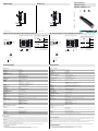
Abmessungen
Elektrischer Anschluss/Kurven/
Zusätzliche Informationen
Electrical Connection / Curves / Additional Information
Dimensions
Technische Daten Technical data
UB1000-18GM75-E7-V15
48
75
85
M12 x 1
M18 x 1
4
24
LEDs
48
75
85
M12 x 1
M18 x 1
4
24
LEDs
Normsymbol/Anschluss:
(Version E7, npn)
Schaltausgang 1
Schaltausgang 2
Lerneingang
Adernfarben gemäß EN 60947-5-2.
1
4
5
3
2
+ UB
- UB
(BN)
(BK)
(WH)
(GY)
(BU)
U
1
3
4
5
2
0 200 400 600 800 1000 1200 1400 1600
250
200
150
100
5
0
-50
-100
-150
-200
-250
X
Y
Abstand X [mm]
Charakteristische Ansprechkurve
Abstand Y [mm]
ebene Platte 100 mm x 100 mm
Rundstab Ø 25 mm
breite Schallkeule
schmale Schallkeule
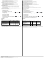
1.
2.
3.
Programmierung der Schaltausgänge
Schaltausgang 1
(Schließer)
Schaltausgang 2
(Schließer)
Schaltpunkt 1 -> ∞: Schaltausgang 1, (
Öffner)
Detektion auf Objektanwesenheit
Schaltpunkt 2 -> ∞: Schaltausgang 2, (
Schließer)
Detektion auf Objektanwesenheit
Schaltpunkt 1 u. 2 -> ∞: beide Schaltausgänge, (
Schließer)
Detektion auf Objektanwesenheit
Objektabstand
Schaltausgang 2
(Öffner)
Schaltausgang 1
(Öffner)
Objektabstand
Schaltpunkt 1 Schaltpunkt 2
Schaltpunkt 2 Schaltpunkt 1
1.
2.
3.
Programmed switching output function
Switch output 1
(N.O.)
Switch output 2
(N.O.)
object range
Switch output 2
(N.C.)
Switch output 1
(N.C.)
object range
Switch point 1 -> ∞: Switch output 1, (N.C.)
Detection of object presence
Switch point 2 -> ∞: Switch output 2, (N.O.)
Detection of object presence
Switch point 1 a. 2 -> ∞: Both switch outputs, (N.O.)
Detection of object presence
Switch point
1
Switch point
2
Switch point
2
Switch point
1
0 200 400 600 800 1000 1200 1400 1600
250
200
150
100
5
0
-50
-100
-150
-200
-250
X
Y
Characteristic response curve
Distance X [mm]
Distance Y [mm]
flat surface 100 mm x 100 mm
round bar, Ø 25 mm
wide sound lobe
narrow sound lobe
Standard symbol/Connections:
(version E7, npn)
Switch output 1
Switch output 2
Teaching input
Core colours in accordance with EN 60947-5-2.
1
4
5
3
2
+ UB
- UB
(BN)
(BK)
(WH)
(GY)
(BU)
U
1
3
4
5
2
Partnummer / Part. No.:
Datum / Date:
204532
04/01/2015 DIN A3 -> DIN
45-2302B
Doc. No.:
1 BN
2 WH
3 BU
4 BK
5 GY
Wire colors in accordance with EN 60947-5-2
(brown)
(white)
(blue)
(black)
(gray)
1 BN
2 WH
3 BU
4 BK
5 GY
Adernfarben gemäß EN 60947-5-2
(braun)
(weiß)
(blau)
(schwarz)
(grau)
Beschreibung der Sensorfunktionen
Programmierung
Der Sensor ist mit zwei programmierbaren Schaltausgängen mit je einem programmierbaren Schaltpunkt ausgestattet. Das Programmieren der
Schaltpunkte und der Betriebsart wird durch Anlegen der Spannung -UB oder +UB an den Lerneingang vorgenommen. Die Versorgungsspannung
muss mindestens 1 s lang am Lerneingang anliegen. LEDs zeigen an, ob der Sensor das Zielobjekt während des Programmiervorgangs erkennt.
Hinweis:
Ein Einlernen der Schaltpunkte ist nur unmittelbar nach dem Zuschalten der Spannungsversorgung möglich. Ein Zeitschloss sichert 5 Minuten
nach dem letzten Einlernen die eingestellten Werte gegen ungewolltes Verändern. Sollen die Schaltpunkte zu einem späteren Zeitpunkt verändert
werden, so ist dies erst nach einem erneuten Power On möglich.
Hinweis:
Wenn ein Programmieradapter UB-PROG3 zur Programmierung verwendet wird, steht die Taste A1 für -UB und die Taste A2 für +UB.
Programmierung der Schaltausgänge
Schließerfunktion
Der Schaltpunkt des Schaltausgangs 1 muss näher am Sensor liegen als der Schaltpunkt von Schaltausgang 2
1. Positionieren Sie das Zielobjekt am gewünschten Schaltpunkt des Schaltausgangs 1
Allgemeine Daten
Erfassungsbereich 70 ... 1000 mm
Einstellbereich 90 ... 1000 mm
Blindzone 0 ... 70 mm
Normmessplatte 100 mm x 100 mm
Wandlerfrequenz ca. 255 kHz
Ansprechverzug ca. 125 ms
Anzeigen/Bedienelemente
LED gelb Schaltzustandsanzeige
blinkend: Lernfunktion Objekt erkannt
LED rot "Störung", Objekt unsicher
in Lernfunktion: kein Objekt erkannt
Elektrische Daten
Betriebsspannung UB10 ... 30 V DC , Welligkeit 10 %SS
Leerlaufstrom I0≤ 50 mA
Eingang
Eingangstyp 1 Lerneingang
Schaltabstand 1: -UB ... +1 V, Schaltabstand 2: +4 V ... +UB
Eingangsimpedanz: > 4,7 kΩ Lernimpuls: ≥ 1 s
Ausgang
Ausgangstyp 2 Schaltausgänge npn, Schließer/Öffner , parametrierbar
Bemessungsbetriebsstrom Ie2 x 100 mA , kurzschluss-/überlastfest
Spannungsfall Ud≤ 3 V
Reproduzierbarkeit ≤ 1 %
Schaltfrequenz f max. 3 Hz
Abstandshysterese H 1 % des eingestellten Schaltabstandes
Temperatureinfluss ± 1,5 % vom Endwert
Umgebungsbedingungen
Umgebungstemperatur -25 ... 70 °C (-13 ... 158 °F)
Lagertemperatur -40 ... 85 °C (-40 ... 185 °F)
Mechanische Daten
Anschlussart Gerätestecker M12 x 1 , 5-polig
Schutzart IP67
Material
Gehäuse Messing, vernickelt
Wandler Epoxidharz/Glashohlkugelgemisch; Schaum Polyurethan, Deckel PBT
Masse 60 g
Werkseinstellungen
Ausgang 1 Schaltpunkt: 90 mm
Ausgangsfunktion: Schaltpunktfunktion
Ausgangsverhalten: Schließer
Ausgang 2 Schaltpunkt: 1000 mm
Ausgangsfunktion: Schaltpunktfunktion
Ausgangsverhalten: Schließer
Schallkeule breit
Normen- und Richtlinienkonformität
Normenkonformität
Normen EN 60947-5-2:2007
IEC 60947-5-2:2007
Zulassungen und Zertifikate
UL-Zulassung cULus Listed, General Purpose
CSA-Zulassung cCSAus Listed, General Purpose
CCC-Zulassung Produkte, deren max. Betriebsspannung ≤36 V ist, sind nicht zulassungspflichtig und daher nicht mit einer CCC-
Kennzeichnung versehen.
Description of Sensor Functions
Programming procedure
The sensor features two programmable switch outputs with one programmable switch point, each. Programming the switch point and the operating
mode is done by applying the supply voltage -UB or +UB to the Program input. The supply voltage must be applied to the Program input for at least
1 s. LEDs indicate whether the sensor has recognized the target during the programming procedure.
Note:
Switching points may only be specified directly after Power on. A time lock secures the adjusted switching points against unintended modification
5 minutes after Power on. To modify the switching points later, the user may specify the desired values only after a new Power On.
Note:
If a programming adapter UB-PROG3 is used for the programming procedure, button A1 is assigned to -UB and button A2 is assigned to +UB.
Programming switch ouputs
Normally open (NO) output
The switch point of switch output 1 has to be closer to the sensor than the switch point of switch output 2
1. Place the target at the desired switch point position of switch output 1
2. Program the switch point by applying -UB to the Program input (corresponding yellow LED flashes)
General specifications
Sensing range 70 ... 1000 mm
Adjustment range 90 ... 1000 mm
Unusable area 0 ... 70 mm
Standard target plate 100 mm x 100 mm
Transducer frequency approx. 255 kHz
Response delay approx. 125 ms
Indicators/operating means
LED yellow indication of the switching state
flashing: program function object detected
LED red "Error", object uncertain
in program function: No object detected
Electrical specifications
Operating voltage UB10 ... 30 V DC , ripple 10 %SS
No-load supply current I0≤ 50 mA
Input
Input type 1 program input,
operating range 1: -UB ... +1 V, operating range 2: +4 V ... +UB
input impedance: > 4.7 kΩ; program pulse: ≥ 1 s
Output
Output type 2 switch outputs NPN, normally open/closed , programmable
Rated operating current Ie2 x 100 mA , short-circuit/overload protected
Voltage drop Ud≤ 3 V
Repeat accuracy ≤ 1 %
Switching frequency f max. 3 Hz
Range hysteresis H 1 % of the set operating distance
Temperature influence ± 1.5 % of full-scale value
Ambient conditions
Ambient temperature -25 ... 70 °C (-13 ... 158 °F)
Storage temperature -40 ... 85 °C (-40 ... 185 °F)
Mechanical specifications
Connection type Connector M12 x 1 , 5-pin
Degree of protection IP67
Material
Housing brass, nickel-plated
Transducer epoxy resin/hollow glass sphere mixture; foam polyurethane, cover PBT
Mass 60 g
Factory settings
Output 1 Switching point: 90 mm
output function: Switch point operation mode
output behavior: NO contact
Output 2 Switching point: 1000 mm
output function: Switch point operation mode
output behavior: NO contact
Beam width wide
Compliance with standards and directives
Standard conformity
Standards EN 60947-5-2:2007
IEC 60947-5-2:2007
Approvals and certificates
UL approval cULus Listed, General Purpose
CSA approval cCSAus Listed, General Purpose
CCC approval CCC approval / marking not required for products rated ≤36 V
Ultraschallsensor
Ultrasonic sensor
Alle Abmessungen in mm All dimensions im mm

Adressen / Addresses / Adresses / Direcciónes / Indirizzi
Contact Pepperl+Fuchs GmbH · 68301 Mannheim · Germany · Tel. +49 621 776-4411 · Fax +49 621 776-27-4411 · E-mail: [email protected]l-fuchs.com
Worldwide Headquarters: Pepperl+Fuchs GmbH · Mannheim · Germany · E-mail: info@de.pepperl-fuchs.com
USA Headquarters: Pepperl+Fuchs Inc. · Twinsburg · USA · E-mail: fa-info@us.pepperl-fuchs.com
Asia Pacific Headquarters: Pepperl+Fuchs Pte Ltd · Singapore · E-mail: [email protected]perl-fuchs.com · Company Registration No. 199003130E
For more contact-adresses refer to the catalogue or internet: http://www.pepperl-fuchs.com
2. Programmieren Sie den Schaltpunkt durch Anlegen von -UB an den Lerneingang (zugehörige gelbe LED blinkt)
3. Zum Speichern des Schaltpunktes trennen Sie den Lerneingang von -UB
4. Positionieren Sie das Zielobjekt am gewünschten Schaltpunkt des Schaltausgangs 2
5. Programmieren Sie den Schaltpunkt durch Anlegen von +UB an den Lerneingang (zugehörige gelbe LED blinkt)
6. Zum Speichern des Schaltpunktes trennen Sie den Lerneingang von +UB
Hinweis: Die Reihenfolge spielt dabei keine Rolle, es kann auch nur ein Schaltpunkt eingelernt werden.
Öffnerfunktion
Der Schaltpunkt des Schaltausgangs 2 muss näher am Sensor liegen als der Schaltpunkt von Schaltausgang 1
1. Positionieren Sie das Zielobjekt am gewünschten Schaltpunkt des Schaltausgangs 1
2. Programmieren Sie den Schaltpunkt durch Anlegen von -UB an den Lerneingang (zugehörige gelbe LED blinkt)
3. Zum Speichern des Schaltpunktes trennen Sie den Lerneingang von -UB
4. Positionieren Sie das Zielobjekt am gewünschten Schaltpunkt des Schaltausgangs 2
5. Programmieren Sie den Schaltpunkt durch Anlegen von +UB an den Lerneingang (zugehörige gelbe LED blinkt)
6. Zum Speichern des Schaltpunktes trennen Sie den Lerneingang von +UB
Hinweis: Die Reihenfolge spielt dabei keine Rolle, es kann auch nur ein Schaltpunkt eingelernt werden. Sind beide Schaltpunkte
gleich, arbeitet der Sensor im Schließermodus.
Detektion auf Objektanwesenheit
1. Decken Sie den Sensor mit der Handfläche ab oder entfernen Sie alle Objekte aus dem Erfassungsbereich des Sensors
2. Programmieren Sie den Schaltpunkt von Schaltausgang 1 durch Anlegen von -UB an den Lerneingang (rote LED blinkt)
3. Trennen Sie den Lerneingang von -UB
4. Programmieren Sie den Schaltpunkt von Schaltausgang 2 durch Anlegen von +UB an den Lerneingang (rote LED blinkt)
5. Trennen Sie den Lerneingang von +UB
Hinweis: Es kann auch nur ein Schaltausgang für die Detektion auf Objektanwesenheit eingelernt werden. In dieser Konfiguration schaltet
der Schaltausgang, wenn vom Sensor innerhalb des maximalen Erfassungsbereichs ein Objekt erkannt wird.
Einstellen der Ultraschallkeulen-Charakteristik:
Der Ultraschall-Sensor bietet 2 verschiedene Schallkeulenformen.
1. Schmale Ultraschallkeule
• Spannungsversorgung abschalten
• Lerneingang mit -UB verbinden
• Spannungsversorgung zuschalten
• die rote LED blinkt einfach, gefolgt von einer Pause
• gelbe LED: permanent ein: signalisiert Objekt/Störobjekt im Erfas-
sungsbereich vorhanden
• Lerneingang von -UB trennen
2. Breite Ultraschallkeule
• Spannungsversorgung abschalten
• Lerneingang mit +UB verbinden
• Spannungsversorgung zuschalten
• die rote LED blinkt doppelt, gefolgt von einer Pause
• gelbe LED: permanent ein: signalisiert Objekt/Störobjekt im Erfas-
sungsbereich vorhanden
• Lerneingang von +UB trennen
Werkseinstellung
Siehe Technische Daten
Anzeigen
Der Sensor ist mit LEDs zur Anzeige der Betriebszustände ausgestattet.
Einbaubedingungen
Bei einem Einbau des Sensors an Orten, an denen die Betriebstemperatur unter 0 °C sinken kann, müssen zur Montage die Befestigungsflansche
BF18, BF18-F oder BF 5-30 verwendet werden.
Soll der Sensor direkt in einer Durchgangsbohrung montiert werden, so ist unter Verwendung der beiliegenden Stahlmuttern die Befestigung in
der Mitte der Sensorhülse vorzunehmen. Für eine Verschraubung im vorderen Bereich der Gewindehülse sind die als Zubehör erhältlichen Kunst-
stoffmuttern mit Zentrierring zu verwenden.
rote LED gelbe LED 1 gelbe LED 2
Im normalen Betrieb
störungsfreier Betrieb
Störung (z. B. Druckluft)
aus
ein
Schaltzustand
Ausgang 1
letzter gültiger Zustand
Schaltzustand
Ausgang 2
letzter gültiger Zustand
Programmierung Schaltausgang 1
Objekt erkannt
kein Objekt erkannt
Objekt unsicher (Programmierung ungültig)
aus
blinkend
ein
blinkend
aus
aus
aus
aus
aus
Programmierung Schaltausgang 2
Objekt erkannt
kein Objekt erkannt
Objekt unsicher (Programmierung ungültig)
aus
blinkend
ein
aus
aus
aus
blinkend
aus
aus
Pause
Pause
3. Disconnect the Program input from -UB to save the switch point
4. Place the target at the desired switch point position of switch output 2
5. Program the switch point by applying +UB to the Program input (corresponding yellow LED flashes)
6. Disconnect the Program input from +UB to save the switch point
Note: The order doesn't make any difference. If you want, you can set only one switching point.
Normally closed (NC) output
The switch point of switch output 2 has to be closer to the sensor than the switch point of switch output 1
1. Place the target at the desired switch point position of switch output 1
2. Program the switch point by applying -UB to the Program input (corresponding yellow LED flashes)
3. Disconnect the Program input from -UB to save the switch point
4. Place the target at the desired switch point position of switch output 2
5. Program the switch point by applying +UB to the Program input (corresponding yellow LED flashes)
6. Disconnect the Program input from +UB to save the switch point
Note: The order doesn't make any difference. If you want, you can set only one switching point. If both switching points
are equal, the sensor works in close function.
Programming detection of object presence
1. Cover the sensor face with hand or remove all objects from sensing range
2. Apply -UB to the Program input (red LED flashes)
3. Disconnect the Program input from -UB
4. Apply +UB to the Program input (red LED flashes)
5. Disconnect the Program input from +UB
Note: Only one switch output can be configured for detection of presence of objects. If the sensor detects an object within the maximum
detection range, the switch output switches.
Adjusting the sound cone characteristics:
The ultrasonic sensor enables two different shapes of the sound cone, a wide angle sound cone and a small angle sound cone.
1. Small angle sound cone
• switch off the power supply
• connect the Teach-In input wire to -UB
• switch on the power supply
• the red LED flashes once with a pause before the next.
• yellow LED: permanently on: indicates the presence of an object or
disturbing object within the sensing range
• disconnect the Teach-In input wire from -UB and the changing is saved
2. Wide angle sound cone
• switch off the power supply
• connect the Teach-In input wire with +UB
• switch on the power supply
• the red LED double-flashes with a long pause before the next.
• yellow LED: permanently on: indicates an object or disturbing object
within the sensing range
• disconnect the Teach-In input wire from +UB and the changing is saved
Factory settings
See technical data.
Display
The sensor provides LEDs to indicate various conditions.
Installation conditions
If the sensor is installed at places, where the environment temperature can fall below 0 °C, for the sensors fixation, one of the mounting flanges BF18,
BF18-F or BF 5-30 must be used.
In case of direct mounting of the sensor in a through hole using the steel nuts, it has to be fixed at the middle of the housing thread. If a fixation at the
front end of the threaded housing is required, plastic nuts with centering ring (accessories) must be used.
Red LED Yellow LED 1 Yellow LED 2
During Normal operation
Proper operation
Interference (e.g. compressed air)
Off
On
Switching state
output 1
remains in previous state
Switching state
output 2
remains in previous state
Programming of output 1
Object detected
No object detected
Object uncertain (programming invalid)
Off
Flashes
On
Flashes
Off
Off
Off
Off
Off
Programming of output 2
Object detected
No object detected
Object uncertain (programming invalid)
Off
Flashes
On
Off
Off
Off
Flashes
Off
Off
pause
pause
-
 1
1
-
 2
2


Pepperl+Fuchs UB1000-18GM75-E7-V15 Bedienungsanleitung
- Typ
- Bedienungsanleitung
in anderen Sprachen
Verwandte Artikel
-
Pepperl+Fuchs UB500-18GM75-E01-V15 Bedienungsanleitung
-
-
-
-
-
-
-
-
-