
Central Locking with Infra-Red Remote Control
for Do-It-Yourself Installation
Zentralverriegelung mit Infrarotfernbedienung
zum Nachrüsten
Montage-
und Bedienungsanleitung
Assembly
and operating instructions

H
E
F
B/C
I
G
Abb. 2
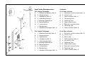
Inhalt eines Montagesatzes
Für 2-türige Fahrzeuge
A 1 Elektronik-Steuerteil (Abb. 3)
B 2 Steuereinheiten
D 1 Kabelbaum (Abb. 3)
E 2 Verbindungsstangen
F 2 Befestigungsklemmen
G 8 Blechschrauben
H 2 Lochschienen
I 4 Blechmuttern
J 2 Kabeldurchführungen (Abb. 2)
Für 4-türige Fahrzeuge
A 1 Elektronik-Steuerteil (Abb. 3)
B 2 Steuereinheiten
C 2 Stelleinheiten
D 1 Kabelbaum (Abb. 3)
E 4 Verbindungsstangen
F 4 Befestigungsklemmen
G 16 Blechschrauben
H 4 Lochschienen
I 8 Blechmuttern
J 4 Kabeldurchführungen (Abb. 2)
Contents
For 2-door vehicles
A 1 Electronic control module (Abb. 3)
B 2 Control units
D 1 Cable harness (Abb. 3)
E 2 Connecting rods
F 2 Fastening clips
G 8 Sheet metal screws
H 2 Rails with punched holes
I 4 Fastening nuts
J 2 Cable conducts (Abb. 2)
For 4-door vehicles
A 1 Electronic control module (Abb. 3)
B 2 Control units
C 2 Servo units
D 1 Cable harness (Abb. 3)
E 4 Connecting rods
F 4 Fastening clips
G 16 Sheet metal screws
H 4 Rails with punched holes
I 8 Fastening nuts
J 4 Cable conducts (Abb. 2)
2

J
Tür
door
2
1
vordere Tür
front door
hintere Tür
rear door
vordere Tür
front door
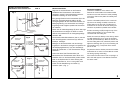
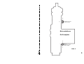
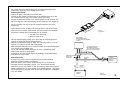
Einbau der Steuereinheiten
Installation of the control unit
Abb. 2
1 = verriegelt
1 = locked
2 = entriegelt
2 = unlocked
1 = verriegelt
1 = locked
2 = entriegelt
2 = unlocked
1
2
2121
1
2
1
2
Fig. 1
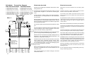
Mechanischer Einbau
Beginnen Sie mit dem Einbau an der Fahrertür.
Handkurbel des Fensterhebers und Armlehne
abnehmen und die Türinnenverkleidung entfernen.
Plastikfolie vorsichtig von unten her lösen.
Eine günstige Position für die Steuereinheit (B) in der
Nähe der Verriegelungsstange wählen, die den
Verriegelungsknopf mit dem Türschloß verbindet. Die
Bewegungsrichtung von Steuereinheit und Verriege-
lungsstange sollte möglichst parallel und hintereinan-
der verlaufen.
Ziehen Sie die Verbindungsstange (E) durch das Auge
der Steuereinheit und biegen Sie diese so zurecht,
daß sie sich problemlos mit der Verriegelungsstange
verbinden läßt.
Steuereinheit mittels Bohrschablone (Abb. 4) oder mit
einer der beiliegenden Lochschienen (H) direkt am
Türkörper befestigen.
Bewegen Sie die Steuereinheit und den Verriege-
lungsknopf in die Position “entriegelt” und justieren Sie
die Befestigungsklemmen (F )auf der Verbindungs-
stange (E) gemäß Abb. 1. Den Überstand der Stange
abkneifen.
Achten Sie darauf, daß Fensterscheibe und
Mechanismus des Fensterhebers beim Öffnen und
Schließen nicht von der Steuereinheit berührt werden.
Falls an der Kopfseite der Tür keine Öffnung oder
Bohrung vorhanden ist, ein ca. 9 mm großes Loch
bohren und die Kabelführung aus Gummi (J)
einsetzen. (Abb. 2, Fig. 1)
Mechanical installation
Commence installation on the driver’s door.
Remove the crank handle of the window winder
and the arm rest and remove the inside panelling
of the door. Remove the plastic foil carefully from
the bottom.
Choose a favourable position for the control unit
(B) close to the locking rod which connects the
locking button to the door lock. The direction of
movement of the control unit and the locking rod
should be as parallel as possible and in tandem.
Pull the connecting rod (E) through the eye of the
control unit and bend it so as to provide easy
connection with the locking bar.
Attach the control unit directly to the door by means
of a drill template (Fig. 4) or one of the enclosed
rails with punched holes (H). Move the control unit
and the locking button into “unlocked” position and
adjust the fastening clips (F) on the connecting rod
(E) according to Fig. 1 and pinch off the excess
part of the rod.
Pay attention that the window pane and the winder
mechanism do not come in contact with the control
unit during opening and closing.
If the head of the door has no hole or opening in it,
drill a hole with approx. 9 mm diameter and insert
the rubber cable
Fig. 2
Fig. 3
3
hintere Tür
rear door

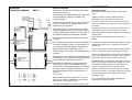
Schaltplan
Connection diagram
Abb. 3
alles einwandfrei arbeitet.
Electrical connection
Disconnect the minus terminal from the battery when
wiring.
Install the electronic control module beneath the
dashboard, as near as possible to the fuse box.
Lay out the 5-core cable to the control units in the front
doors. Connect the 2-core cable to the control units of the
rear doors.
Pay attention that there is about 10 cm clearance for the
cable between the door and the beam of the vehicle.
Avoid sharp edges and bind the cable in insulation tape at
contact points.
Black cable to be fixed directly at the minus pole of
batterie.
Connect the red cable with built-in fuse directly to the plus
terminal of the battery or to a continuous current line in
the fuse box.
Connect the electronic control module and cable harness
(D) by connecting the 6-pole compact plug-in coupling.
Press in the cable connector of the control units according
to the wiring diagram until they engage in the correspon-
ding socket connectors of the electric cable harness.
ATTENTION when connecting the control units of the rear
doors: Do not let the connectors fully engage! As a result
of a different installation of the servo units, these may
have to be changed in order to achieve the same
direction of movement of the control units (Fig. 2 and 3).
Reconnect the battery. Check that all doors can be locked
and unlocked by key from the driver’s and the front
passenger’s door.
Do not reinstall foil and door inside panelling until
everything is functioning properly.
Elektrischer Anschluß
Klemmen Sie den Minuspol der Batterie während der
Verkabelungsarbeiten ab.
Die Befestigung des Elektronik-Steuerteils erfolgt unter
dem Armaturenbrett, möglichst in der Nähe des
Sicherungskastens.
Verlegen Sie die 5-adrigen Kabel zu den Steuereinhei-
ten in den Vordertüren, die 2-adrigen Kabel zu den
Stelleinheiten der Hintertüren.
Berücksichtigen Sie, daß zwischen der Tür und dem
Holm des Fahrzeuges etwa 10 cm Kabel Spiel bleiben
müssen. Scharfe Kanten vermeiden und das Kabel an
den Berührungspunkten mit Isolierband umwickeln.
Das schwarze Kabel direkt am Minuspol der Batterie
anbringen.
Das rote Kabel mit eingebauter Sicherung wird direkt an
den Pluspol der Batterie oder im Sicherungskasten an
eine Dauerstrom führende Zuleitung angeschlossen.
Elektronik-Steuerteil und Kabelbaum (D) durch
Zusammenfügen der 6-poligen Kompaktsteckkupplung
verbinden.
Kabelstecker der Steuereinheiten gemäß Schaltplan bis
zum Einrasten in die entsprechenden Verbindungsstek-
ker des elektrischen Kabelsatzes eindrücken.
ACHTUNG beim Anschluß der Steuereinheiten der
hinteren Türen: Stecker nicht vollständig einrasten
lassen! Durch unterschiedliche Montage der Stelleinhei-
ten müssen diese evtl. umgewechselt werden, um die
gleiche Bewegungsrichtung der Steuereinheiten zu
erreichen.
(Fig. 2 und 3).
Batterie wieder anklemmen. Prüfen Sie, ob sich alle
Türen von der Fahrer- und Beifahrertür aus mit dem
Schlüssel ver- und entriegeln lassen.
Folie und Türverkleidung erst wieder anbringen, wenn
bl
gr
br
w
sc
ro
=
=
=
=
=
=
blau
grün
braun
weiß
schwarz
rot
bl
gr
br
w
sc
ro
=
=
=
=
=
=
blue
green
brown
white
black
red
4
Steuereinheiten
Stellmotoren
hinten
Servo motors, rear
gr
gr
bl
bl
gr
br
w
sc
bl
auf
open
- 12 V
zu
close
-12 V
externe Steuerung
external control
sc
ro
Steuereinheiten
Stellmotoren
vorne
Servo motors,
front
sc
ro
Batterie
Battery
Steuerrelais
Zentralverriegelung
Control relay, central
door locking
D
A

Abb. 4
Bohrschablone
Drill template
Bohrung ø 5 mm
Hole, ø 5 mm
Bohrung ø 5 mm
Hole, ø 5 mm
5

Abb. 3
Electrical connection
Disconnect the minus terminal from the battery when
wiring.
Install the electronic control module beneath the dash-
board, as near as possible to the fuse box.
Lay out the 5-core cable to the control units in the front
doors. Connect the 2-core cable to the control units of the
rear doors.
Pay attention that there is about 10 cm clearance for the
cable between the door and the beam of the vehicle. Avoid
sharp edges and bind the cable in insulation tape at
contact points.
Black cable to be fixed directly at the minus pole of batterie.
Connect the red cable with built-in fuse directly to the plus
terminal of the battery or to a continuous current line in the
fuse box.
Connect the electronic control module and cable harness
(D) by connecting the 6-pole compact plug-in coupling.
Press in the cable connector of the control units according
to the wiring diagram until they engage in the correspon-
ding socket connectors of the electric cable harness.
ATTENTION when connecting the control units of the rear
doors: Do not let the connectors fully engage! As a result
of a different installation of the servo units, these may have
to be changed in order to achieve the same direction of
movement of the control units (Fig. 2 and 3).
Reconnect the battery. Check that all doors can be locked
and unlocked by key from the driver’s and the front
passenger’s door.
Do not reinstall foil and door inside panelling until every-
thing is functioning properly.
Elektrischer Anschluß
Klemmen Sie den Minuspol der Batterie während der Verka-
belungsarbeiten ab.
Die Befestigung des Elektronik-Steuerteils erfolgt unter dem
Armaturenbrett, möglichst in der Nähe des Sicherungska-
stens.
Verlegen Sie die 5-adrigen Kabel zu den Steuereinheiten in
den Vordertüren, die 2-adrigen Kabel zu den Stelleinheiten
der Hintertüren.
Berücksichtigen Sie, daß zwischen der Tür und dem Holm des
Fahrzeuges etwa 10 cm Kabel Spiel bleiben müssen. Scharfe
Kanten vermeiden und das Kabel an den Berührungspunkten
mit Isolierband umwickeln.
Das schwarze Kabel direkt am Minuspol der Batterie anbrin-
gen.
Das rote Kabel mit eingebauter Sicherung wird direkt an den
Pluspol der Batterie oder im Sicherungskasten an eine Dau-
erstrom führende Zuleitung angeschlossen.
Elektronik-Steuerteil und Kabelbaum (D) durch Zusammenfü-
gen der 6-poligen Kompaktsteckkupplung verbinden.
Kabelstecker der Steuereinheiten gemäß Schaltplan bis zum
Einrasten in die entsprechenden Verbindungsstecker des
elektrischen Kabelsatzes eindrücken.
ACHTUNG beim Anschluß der Steuereinheiten der hinteren
Türen: Stecker nicht vollständig einrasten lassen! Durch
unterschiedliche Montage der Stelleinheiten müssen diese
evtl. umgewechselt werden, um die gleiche Bewegungsrich-
tung der Steuereinheiten zu erreichen.
(Fig. 2 und 3).
Batterie wieder anklemmen. Prüfen Sie, ob sich alle Türen von
der Fahrer- und Beifahrertür aus mit dem Schlüssel ver- und
entriegeln lassen.
Folie und Türverkleidung erst wieder anbringen, wenn alles
einwandfrei arbeitet.
bl
gr
br
w
sc
ro
=
=
=
=
=
=
blau
grün
braun
weiß
schwarz
rot
bl
gr
br
w
sc
ro
=
=
=
=
=
=
blue
green
brown
white
black
red
bl
gr
br
w
sc
ro
bleu
gris
marron
blanc
noir
rouge
=
=
=
=
=
=
blauw
groen
bruin
wit
zwart
rood
=
=
=
=
=
=
Steuereinheiten
Stellmotoren vorne
Servo motors, front
Moteurs de
manoeuvre avant
Stelmotoren voor
Steuereinheiten
Stellmotoren hinten
Servo motors, rear
Moteurs de
manoeuvre arrière
Stelmotoren achter
D
A
Schaltplan Connection diagram
Plan de branchement Aansluitschema
bl
gr
br
w
sc
ro
6
Masse (-)
GND (-)
4 = externe Steuerung +12V = ZV "auf"
4 = exetrnal control +12V = ZV "open"
4 = réglage exterieur +12V = ZV "ouvert"
4 = externe besteuring +12V = ZV "open"
9 = externe Steuerung +12V = ZV "zu"
9 = exetrnal control +12V = ZV "close"
9 = réglage exterieur +12V = ZV "fermé"
9 = externe besteuring +12V = ZV "gesloten"
5 = externe Steuerung Masse (-) = ZV "auf"
5 = exetrnal control GND (-) = ZV "open"
5 = réglage exterieur GND (-) = ZV "ouvert"
5 = externe besteuring
GND (-)
= ZV "
open
"
10= externe Steuerung Masse (-) = ZV "zu"
10= exetrnal control GND (-) = ZV "close"
10= réglage exterieur GND (-) = ZV "fermé"
10= externe besteuring GND (-) = ZV
"gesloten"

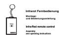
Infrarot Fernbedienung
Assembly
and operating instructions
Montage-
und Bedienungsanleitung
Infra-Red remote control

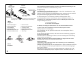
Das Steuerrelais der Zentralverriegelung verfügt über eine elektrische Vorbereitung, die den
problemlosen Anschluß der Infrarotfernbedienung erlaubt.
Montageanleitung:
Anschlußstecker des Infrarot-Empfangsteil, 2-polig, mit dem freien Anschlußstecker, 2-polig,
des Zentralverriegelungssteuerrelais verbinden.
Schwarze und rote Leitung des Anschlußkabelsatzes mit der schwarzen und roten Anschluß-
leitung des Zentralverriegelungssteuermoduls verbinden (siehe auch Abb. 2).
Für die Anbindung die 2 im Lieferumfang enthaltenen Abzweigverbinder nutzen.
Infrarot-Empfangsteil montieren. Dabei beachten, daß zur einwandfreien Funktion der
Fernbedienung eine Sichtverbindung zwischen Sender und Empfangsteil bestehen muß.
Geeignete Montageorte sind z.B:
1. Armaturenbrettoberseite
2. In der Nähe des Innenspiegels.
Zur Montage die beigefügten Blechschrauben oder das Klettverschlußband benutzen.
4-poligen Stecker des Anschlußkabels mit dem Infrarot-Empfangsteil verbinden.
Achtung: Hinweise zur Kabelverlegung
Das Anschlußkabel darf nicht gequetscht werden sowie nicht mit beweglichen Teilen in
Berührung kommen.
Bei der Verlegung des Kabels beachten, daß dieses nicht durch Verwendung ungeeigneter
Werkzeuge beschädigt wird.
Das Kabel nicht hinter Türdichtungen schieben; nicht hinter festanliegende Fensterdichtung
verlegen (Gefahr von Glasbruch).
Möglichst das Kabel hinter Fahrzeug-Original-Verkleidungen verlegen oder unter solche
Fensterdichtungen schieben, die sich leicht anheben lassen.
Bedienungsanleitung:
Voraussetzung für die einwandfreie Funktion der Fernbedienung ist eine Sichtverbindung
zwischen Sender und Empfangsteil.
Unterhalb einer Distanz von ca. 4 m zum Empfangsteil ist es möglich, nachdem der Sender für
ca. 1 Sek. betätigt und auf das Empfangsteil ausgerichtet wurde, die Zentralverriegelung zu
öffnen und zu schließen.
Bitte beachten Sie, daß -da es sich um ein Infrarot-Gerät handelt- nur Signale, die an die
Vorderseite des Empfangsteils gelangen, ausgewertet werden - siehe hierzu auch Abb. 3.
Abb.1
1 Infrarot Empfangsteil
2 Infrarot Handsender
1 Anschlußkabel
2 Abzweigverbinder
2 Blechschrauben 2x12 mm
1 Klettverschlußklebeband
Diagram 1
1 Infrared receiver
2 Infrared hand transmitters
1 connecting cable
2 Snap-lock connectors
2 tapping screws 2 x 12 mm
1 Velcro tape
Abzweigverbinder
Snap-lock connector
Abb. 2
Diagram 2
Infrarot
Empfangsteil
infrared receiver
Handsender
hand transmitter
Anschlußkabel
connecting cable
Blechschrauben
tapping screws
Spannungsversorgung
power supply
Anschlußstecker für Zentralveriegelung
connector plug for central locking
Inhalt Contents
8

Infrarot
Empfangsteil
infrared
receiver
schwarz
black
rot
red
Steuerrelais
Zentralverriegelung
Control relay, central door
locking
2 poliger Stecker für
Zentralverriegelung
Two contacts connector
for central door locking
6 poliger Stecker
Six contacts connector
Abzweigverbinder
Snap-lock
connector
Abb. 3
Diagram 3
Abb. 4
Diagram 4
The control relay of the central locking has an electrical preparation which
enables easy connection of the infrared remote control.
Assembly instructions:
Localize the place of assembly of the control relay.
Connect the two contacts connector plugs of the infrared receiver to the free
two contacts connector plugs of the central locking control relay.
Connect the black and red wire of the connecting cable set with the black and
red connecting wire of the central locking control module (see also diagram 2).
For the connection use the 2 snap-lock connectors which are part of the
supplied set.
Fit the infrared receiver. In doing so do not forget that in order for the remote
control to function properly, visual contact must exist between the transmitter
and receiver. Suitable places for assembly are, for example:
1. Top side of the dashboard
2. Near the inside mirror.
Use the enclosed tapping screws or the Velcro tape for assembly purposes.
Connect the 4-pin plug with the infrared receiver.
Attention: Instructions for laying the cable. The connecting cable is not to be
crushed or to come into contact with mowing parts.
When laying the cable take care to ensure that these do not become damaged
as a result of using unsuitable tools.
Do not push the cable behind door seals: do not lay it behind firmly fixed
window seals (danger of broken glass).
If possible lay the cable behind original car panelling or underneath window
seals which are easy to raise.
Instruction for use:
In order for the remote control to operate perfectly, a visual contact is
necessary between transmitter and receiver.
When the distance to the receiver is less than approx. 4 m and after the
transmitter has been activated for approx. 1 sec. and has been directed
towards the receiver, it is possible to open and close the central locking system.
Please remember that - as it is a question of an infrared appliance - only signals
that get through to the front side of the receiver will be evaluated - see diagram
3 for more details.
9
Batterie
Battery
schwarz
black
rot
red

10
Notizen

11
Notizen

International
D WAECO - Wähning & Co. GmbH • D-48282 Emsdetten • Sinninger Str. 36 • Tel. 0 25 72/8 79-0 • Fax 0 25 72/8 48 81
A WAECO Handelsgesellschaft mbH • A-5023 Salzburg • Linzer Bundesstraße 67 a • Tel. 06 62/66 09 46 + 66 05 03 • Fax 06 62/66 01 40
CH WAECO Cresta-Cool AG • CH-8153 Rümlang (Zürich) • Glattalstraße 501 • Tel. 01/8 17 30 31 • Fax 01/8 17 33 00
DK WAECO Danmark AS • DK-6640 Lunderskov • Tværvej 2 • Tel. 75 58 59 66 • Fax 75 58 63 07
E WAECO Ibérica S.A. • E-08320 El Masnou (Barcelona) • Avenida Generalitat de Catalunya, 10 • Tel. 03/5 55 52 11 • Fax 03/5 55 85 65
F WAECO France S.A.R.L. • F-06210 Mandelieu (Cannes) • Parc d’ Activités de la Siagne • N° 21-Bat. 3 • Tel. 0 93/47 07 08 • Fax 0 93/47 81 66
FIN WAECO Finland OY • FIN-00880 Helsinki • Levytie 5 - 7 • Tel. 0/7 59 90 71 • Fax 0/7 55 61 21
N WAECO Norge AS • N-1315 Nesøya (Oslo) • Postboks 28, Broveien 85 • Tel. 66 98 07 79 • Fax 66 98 24 52
NL WAECO Benelux BV • NL-4700 BL Roosendaal • Postbus 14 61 • Ettenseweg 60 • Tel. 0 16 50/8 67 00 • Fax 0 16 50/5 55 62
S WAECO Svenska AB • S-42130 Västra Frölunda (Göteborg) • Gruvgatan 9 • Tel. 0 31/49 00 40 • Fax 0 31/49 51 40
-
 1
1
-
 2
2
-
 3
3
-
 4
4
-
 5
5
-
 6
6
-
 7
7
-
 8
8
-
 9
9
-
 10
10
-
 11
11
-
 12
12


Waeco Waeco magic lock Ml44 Bedienungsanleitung
- Typ
- Bedienungsanleitung
- Dieses Handbuch eignet sich auch für
in anderen Sprachen
Verwandte Artikel
-
Waeco MagicLock ML22, ML44 Bedienungsanleitung
-
-
Waeco MAGIC LOCK ML-RF Bedienungsanleitung
-
-
-
-
Waeco MT100 Bedienungsanleitung
-
-
-