
Betriebsanleitung - Mode d’emploi - Istruzioni per l’uso - Operating Instructions
Fume Extraction Irons

Legen Sie das Lötwerkzeug bei Nichtgebrauch immer in der
Sicherheitsablage ab.
Beschreibung
Weller FE- Lötkolben sind für den Betrieb mit dem Zero-Smog-System konstruiert und mit
einem integrierten Absaugrohr ausgestattet, welches unangenehme und gesundheitsgefähr-
dende Dämpfe dort absaugt, wo sie entstehen: direkt an der Lötspitze. Die Lötspitzen-
temperatur wird dadurch nicht beeinflußt.
Inbetriebnahme
1. Beiliegenden Trichter für Halter gegen den Originaltrichter austauschen. Hierbei beachten,
dass das Absaugrohr beim Ablegen in der oberen Position ist und die Ablagefeder nicht
berührt.
2. Absaugrohr auf die Lötspitze justieren. In Lötposition sollte das Rohrende senkrecht über
der Lötspitze sein.
3. Lötkolben in Sicherheitsablage ablegen.
4. Elektronische Verbindungsleitung des FE- Lötkolbens mit der Versorgungseinheit
verbinden.
FE 50 M an PU S.
FE 50 und MLR 21 FE an alle elektronisch regelbaren Versorgungseinheiten.
FE 75 an alle elektronisch regelbaren Versorgungseinheiten mit 80 W-
Anschlusstechnik.
FE 80 an alle elektronisch regelbaren Versorgungseinheiten mit 80 W-
Anschlusstechnik.
5. Silikon-Absaugschlauch an den Zero-Smog oder an das Vakuum- Rohrsystem
anschließen.
Wartung
Das Absaugrohr ist mit einem kleinen Biegeradius versehen. Dadurch wird das Rohr im
Schaft des Kolbengriffes gehalten.
Sollte sich das Absaugrohr während des Betriebs lockern, kann es durch leichtes
nachbiegen wieder fixiert werden.
Das Absaugrohr sollte einmal täglich mit der beiliegenden Bürste gereinigt werden.
Um Verbrennungen zu vermeiden, sollte dies in kaltem Zustand geschehen.
Bei starker Verschmutzung kann das Absaugrohr in einem abgeschlossenen Behälter in
Reinigungsalkohol (Spiritus) gelegt werden bis sich die Flussmittelrückstände gelöst haben.
Warnung:
Bei der Verwendung von Reinigungsmittel sind die gesetzlichen Sicherheitsvorschriften für
deren Handhabung einzuhalten. Das Reinigungsmittel muss als Sondermüll behandelt
werdeb und nach geltenden örtlichen Bestimmungen entsorgt werden.
Um eine korrekte Funktion sicherzustellen, ist eine regelmäßige Reinigung des
Absaugschlauches erforderlich. Hierzu auch den Schlauch abziehen und auskühlen lassen.
Danach den Schlauch mit den Fingern kneten, bis sich die kondensierten Flußmittelrück-
stände lösen von der Turbine absaugt werden.
Sicherheitshinweise
● Den Lötkolben stets in der Originalablage ablegen.
● Alle brennbaren Gegenstände aus der Nähe des heißen Lötwerkzeuges bringen.
● Geeignete Schutzbekleidung verwenden. Verbrennungsgefahr durch flüssiges Lötzinn.
● Den heißen Lötkolben nie unbeaufsichtigt lassen.
● Arbeiten Sie nicht an unter Spannung stehenden Teilen.
Die Betriebsanleitung der verwendeten Versorgungseinheit ist zu dieser
Betriebsanleitung ergänzend gültig.
Die aktualisierten Betriebsanleitungen finden Sie unter
www.weller-tools.com.
Deutsch
1

En cas de non utilisation de l'outil de soudage, toujours le poser dans la
plaque reposoir de sécurité.
Description
Lers fers à souder Weller FE sont conçus pour être utilisés avec le système Zero-Smog.
Ils sont équipés d’un système d’aspiration des fumées de soudage intégré qui aspire les
fumées désagréables et nocives à la source: directement au niveau de la panne.
La température de la panne n’nen est pas affectée.
Mise en service
1. Remplacer I’entonnoir joint sur le support à la place de I’entonnoir d’origine. Le tube
d’aspiration doit se trouver au dessus et ne pas toucher le ressort quand on repose le fer
sur son support.
2. Ajuster le tube d’aspiration sur la panne. En position de soudage, I’extrèmité du tube doit
être à la verticale de la panne.
3. Reposer le fer sur son support.
4. Relier le cordon de liaison électrique du fer à souder FE à I’unité d’alimentation.
FE 50 M à PU S.
FE 50 et MLR 21 FE à tous les blocs Temtronic.
FE 75 à tous les blocs 80 W.
FE 80 à tous les blocs 80 W.
5. Raccorder le tuyau d’aspiration en silicone au Zero-Smog ou au système à vide.
Entretien
Le tube d’aspiration est légèrement courbé son maintien dans la tige de la poignée du fer. Si
le tube d’aspiration se détache pendant le fonctionnement, il peut à nouveau être fixé en le
courbant légèrement.
Le tube d’aspiration doit être nettoyé quotidiennement avec la brosse jointe. Pour éviter
toute brûlure, effectuer le nettoyage à froid. Si le tube d’aspiration est très sale, il peut être
placé dans un récipient fermé contenant de I’alcool de nettoyage jusqu’à ce que les résidus
de flux soient dissous.
Attention:
Lors de I’utilisation de produits de nettoyage, observer les consignes de séurite légales en
vigueur pour leur manipulation. Le produit de nettoyage entre dans la catégorie des déchets
spéciaux et doit être éliminé conformément à la réglementation locale en vigueur.
Pour garantir le bon fonctionnement, il est également nécessaire de nettoyer régulièrement
le tuyau d’aspiration. Pour ce faire, débrancher le tuyau et le laisser refroidir pius, le rouler
entre les doigts por que les résidus solides de flux se détachent et soient aspirés par la
pompe.
Consignes de sécurité
● Déposer toujours le fer à souder dans le support d’origine.
● Eloigner tous les objets inflammables du fer à souder brûlant.
● Porter des vêtements de protection adéquats. Danger de brûlure par l’étain en fusion.
● Ne jamais laisser le fer à souder brûlant sans surveillance.
● Ne travaillez pas sur des pièces sous tension.
En plus du présent mode d’emploi, observer le mode d’emploi de I’unité d’alimentati-
on utilisée.
Vous trouverez les manuels d'utilisation actualisés sur
www.weller-tools.com.
Français
2

Italiano
3
In caso di non utilizzo, l'utensile di saldatura deve essere sempre
appoggiato sul supporto di sicurezza.
Stili saldanti con dispositivo di aspirazione fumi
Gli stili staldanti Weller FE sono stati concepiti per essere utilizzati in abbinamento al
sistema Zero-Smog. Essi presentano, integrato nell’impugnatura, un dispositivo di
aspirazione che rimuove gli sgradevoli e nocivi fumi della saldatura direttamente dove si
generano: la punta saldante, senza tuttavia influenzarne la temperatura.
Messa in esercizio
1. Sostituire I’imbuto precendentemente utilizzato con quello accluso. Assicurarsi che
riponendo lo stilo, il tubetto di aspirazione sia sopra la punta e che non tocchi la molla di
supporto.
2. Posizionare il tubetto di aspirazione sulla punta saldante. Durante la saldatura I’estremità
del tubetto deve essere allineata verticalmente sopra la punta saldante.
3. Riporre lo stilo nel supporto di sicrezza.
4. Collegare e bloccare con uno scatto il connettore elettrico alla unità di controllo.
FE 50 M alla PU S.
FE 50 ed MLR 21 FE a tutte le unità di controllo Tmtronic.
FE 75 a tutte le stazioni di controllo Temtronic con 80 Watt di potenza.
FE 80 a tutte le stazioni di controllo Temtronic con 80 Watt di potenza.
5. Collegare il tubetto siliconico di aspirazione allo Zero-Smog o al sistema di condotte del
vuoto.
Manutenzione
Il tubetto metallico di aspirazione è leggermente ricurvo per poterlo bloccare nel manico
dello stilo. Se durante I’uso il tubo dovesse allentarsi, è sufficiente piegarlo leggermente per
fissarlo all’impugnatura.
Pulire quotidianamente il tubetto metallico con I’apposito scovolino. Per evitare ustioni
effetture I’operazione con lo stilo freddo. Nel caso di tubetto molto sporce è consigliabile
immergere lo stesso in un recipiente chiuso contenente alcool per uso igienico-sanitario ed
attendere che i residui di flussante si siano sciolti.
Attenzione:
Rispettare le norme e le indicazioni legislative di sicrezza relative all’uso dei detergenti. Il
detergente, dopo I’uso. è un residuo nocivo e deve essere smaltito come previsto dalla
legge.
Per garantire un corretto funzionamento del sistema di aspirazione, è necessario pulire
regolarmente anche il tubetto siliconico di aspirazione. Sfilare il tubo siliconico e lasciarlo
raffreddare quindi polveizzare i vapori condensati di flussante stringendo il tubetto tra le dita
fino a uando la turbina a vuoto li avrà aspirati.
Sicurezza
● Riporre lo stilo brasatore sempre nel suo supporto originale.
● Tenere l’utensile di brasatura lontano da qualsiasi oggetto infiammabile.
● Indossare idónei indumenti protettivi. Pericolo di incendio da stagno liquido.
● Non lasciare mai inosservato lo stilo brasatore caldo.
● Non lavorare su pezzi sotto tensione.
Oltre alle presenti istruzioni d’uso sono da rispettare anche le istruzioni d’uso
dell’unità di alimentazione utilizzata.
Trovate le istruzioni per l'uso aggiornate su www.weller-tools.com.

Always place the soldering tool in the safety rest while not in use.
Description
Weller FE soldering irons are designed for use with the Zero-Smog system and are equipped
with an integrated extraction tube to remove unpleasant and dangerous fumes directly
where they occur: at the solder tip. The tip temperature is not effected.
Setting up
1. Replace the enclosed funnel against the original one. Make sure that the suction tube is
in upper position and does not touch the spring holder when the iron is in rest position.
2. Adjust the extraction tube to the tip. The end of tube should be vertical above the tip
when the iron is in soldering position.
3. Store soldering iron in safety holder.
4. Plug in and latch the electrical connector on the power unit.
FE 50 M to PU S.
FE 50 and MLR 21 FE to all Temtronic power supply units
FE 75 to all power supply units with 80 W.
FE 80 to all power supply units with 80 W.
5. connect the silicone suction hose to the Zero-Smog or vaccum pipe system.
Maintenance
The extraction tube has a small bending radius to hold the tube in the shaft of the soldering
iron handle. If the extraction tube should become loose during use, it can be tightened by
bending slightly.
The extraction tube should be cleaned once daily with the special brush. In order to avoid
burns, the tube should be cleaned only after cooling. If the tube is extremely dirty, it can be
placed in a closed container of cleaning alcohol (Spirit) until the fluxing media residues and
loosened.
Warning:
When using cleaning agents, legal safety regulations regarding their use must be observed.
The cleaning agent must be treated as hazardous waste and must be disposed of according
to curent local guidelines.
In order to ensure correct function, the extraction hose should also be cleaned regularly. The
hose must first be unplugged and allowed to cool. Knead the hose between the fingers until
the condensed fluxing media residues are loosened and are emoved by the turbine.
Safety Informations
● Always place the soldering iron in the original holder.
● Remove all inflammable objects from the proximity of the hot soldering tool.
● Use suitable protective clothing. Risk of burns from liquid solder.
● Never leave the hot soldering iron unsupervised.
● Never work on voltage-carrying parts.
The instructions for the use of the supply unit are valid in addition of these here.
See the updated operating instructions at www.weller-tools.com.
English
4

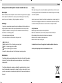
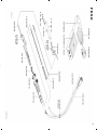
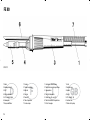
1. Cordone di alimentazione
2. Tubetto siliconico di aspirazione
3. Impugnatura
4. Fermapunta
5. Punta long- life serie PT
6. Tubetto metallico di aspirazione
7. Vite di fissaggio
8. PT-ET Adattatore
1. Kabel
2. Absaugschlauch
3. Griff
4. Spitzenhülse
5. PT- Longlife- Spitze
6. Absaugrohr
7. Biegeschutzfeder
8. PT- ET Adapter
1. Cordon
2. Tuyau d’aspiration
3. Manche
4. Douille pointue
5. Panne PT
6. Tube d’aspiration
7. Vis de serrage
8. PT-ET Adaptateur
1. Cord
2. Suction hose
3. Handle
4. Barrel
5. PT- Longlife- Tip
6. Suction tube
7. Strain relief spring
8. PT-ET Adapter
5
FE 50 M
8.
4.
5.

6
FE 50 M

7
FE 50
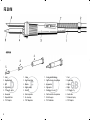
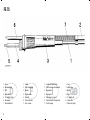
1. Cordone di alimentazione
2. Tubetto siliconico di aspirazione
3. Impugnatura
4. Fermapunta
5. Punta long- life serie ET
6. Tubetto metallico di aspirazione
7. Vite di fissaggio
8. PT-ET Adattatore
1. Kabel
2. Absaugschlauch
3. Griff
4. Spitzenhülse
5. ET- Longlife- Spitze
6. Absaugrohr
7. Biegeschutzfeder
8. PT- ET Adapter
1. Cordon
2. Tuyau d’aspiration
3. Manche
4. Douille pointue
5. Panne ET
6. Tube d’aspiration
7. Vis de serrage
8. PT-ET Adaptateur
1. Cord
2. Suction hose
3. Handle
4. Barrel
5. ET- Longlife- Tip
6. Suction tube
7. Strain relief spring
8. PT-ET Adapter
8.
4.
5.

8
FE 50

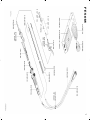
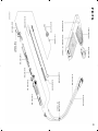
1. Cordone di alimentazione
2. Tubetto siliconico di aspirazione
3. Impugnatura
4. Fermapunta
5. Punta long- life serie LT
6. Tubetto metallico di aspirazione
7. Vite di fissaggio
1. Kabel
2. Absaugschlauch
3. Griff
4. Spitzenhülse
5. LT- Longlife- Spitze
6. Absaugrohr
7. Biegeschutzfeder
1. Cordon
2. Tuyau d’aspiration
3. Manche
4. Douille pointue
5. Panne LT
6. Tube d’aspiration
7. Vis de serrage
1. Cord
2. Suction hose
3. Handle
4. Barrel
5. LT- Longlife- Tip
6. Suction tube
7. Strain relief spring
FE 75
9

10
FE 75

11
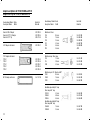
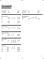
Adapter und Spitzen für FE 50, FE 50M und FE 75
Adapter and Tips for FE 50, FE 50M and FE 75
Beschreibung / Modell Breite Bestell-Nr.
Description / Model Width Order-No.
Meißelform / Chisel
LT H 0,8 mm 5 44 412 00
LT A 1,6 mm 5 44 403 00
LT B 2,4 mm 5 44 405 00
LT C 3,2 mm 5 44 407 00
LT D 4,6 mm 5 44 409 00
ET E 5,6 mm 4ETE
Meißelform lang / Chisel long
LT K 1,2 mm 5 44 413 00
LT L 2,0 mm 5 44 414 00
LT M 3,2 mm 5 44 415 00
Meißelform geb. 30° / Chisel bent 30°
LT HX 0,8 mm 5 44 420 99
LT ALX 1,6 mm 5 44 443 00
LT BX 2,4 mm 5 44 442 00
Rundform abgeschrägt 45° lang
Chisel sloped 45° long
LT CC45 3,2 mm 5 44 445 00
LT DD45 4,0 mm 5 44 478 00
LT DDLL 4,6 mm 5 44 486 00
Rundform abgeschrägt 60° lang
Chisel sloped 60° long
LT AA60 1,6 mm 5 44 487 00
LT BB60 2,4 mm 5 44 444 00
Beschreibung / Modell Breite Bestell-Nr.
Description / Model Width Order-No.
Barrel for MT-LT Adapter 5 87 207 95
Barrel for ET-PT / LT Adapter 5 87 207 94
Barrel for ET, PT Tip 5 10 311 99
ET-LT Adapter with barrel 5 87 207 81
PT-LT Adapter with barrel
PT5-LT 5 87 207 85
PT6-LT 5 87 207 86
PT7-LT 5 87 207 87
PT8-LT 5 87 207 88
PT9-LT 5 87 207 89
MT-LT Adapter with barrel 5 44 121 99

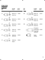
Beschreibung / Modell Breite Bestell-Nr.
Description / Model Width Order-No.
Konisch lang / Conical long
LT 1L Ø 0,2 mm 5 44 423 00
LT S Ø 0,4 mm 5 44 406 00
LT O Ø 0,8 mm 5 44 481 00
LT T Ø 0,6 mm 5 44 482 00
Konisch lang / Conical long
LT 1LX Ø 0,25 mm 5 44 424 00
Lotdepotspitze 45° / Gull wing 45°
LT GW Ø 2,3 mm 5 44 410 00
Ø 3,5 mm 5 44 511 99
Messerspitze / Knife tip
LT KN 6,2 mm 5 44 479 00
Rundform / Round tip
LT 1 Ø 0,25 mm 5 44 401 00
LT AS Ø 1,6 mm 5 44 404 00
LT BS Ø 2,4 mm 5 44 499 00
LT CS Ø 3,2 mm 5 44 411 00
Beschreibung / Modell Breite Bestell-Nr.
Description / Model Width Order-No.
Rundform schlank gebogen 30°
Chisel slim bent 30°
LT 1SLX Ø 2,0 mm 5 44 426 99
12
Spitzen für FE 50, FE 50M und FE75
Tips for FE 50, FE 50M and FE 75

13
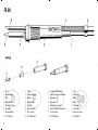
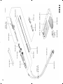
1. Cordone di alimentazione
2. Tubetto siliconico di aspirazione
3. Impugnatura
4. Tubetto fermapunta
5. Punta long- life serie HT
6. Tubetto metallico di aspirazione
7. Vite di fissaggio
1. Kabel
2. Absaugschlauch
3. Griff
4. Spitzengehäuse
5. HT- Longlife- Spitze
6. Absaugrohr
7. Biegeschutzfeder
1. Cordon
2. Tuyau d’aspiration
3. Manche
4. Forreau
5. Panne HT
6. Tube d’aspiration
7. Vis de serrage
1. Cord
2. Suction hose
3. Handle
4. Barrel
5. HT- Longlife- Tip
6. Suction tube
7. Strain relief spring
FE 80

14
HT Spitzen für FE 80
HT Tips for FE 80
Modell Beschreibung Bestell-Nr.
Model Description Order-No.
HT 1 Meißelform 3,2 mm 5 44 260 99
Chisel tip 3,2 mm
HT 2 Meißelform 5,2 mm 5 44 261 99
Chisel tip 5,2 mm
HT 3 Meißelform 7,0 mm 5 44 262 99
Chisel tip 7,0 mm
HT C Flachform 3,2 mm 5 44 267 99
Chisel tip, 3,2 mm
HT D Flachform 4,6 mm 5 44 268 99
Chisel tip 4,6 mm
HT E Flachform 5,6 mm 5 44 269 99
Round tip 3,2
Modell Beschreibung Bestell-Nr.
Model Description Order-No.
HT BS Rundform 2,4 mm 5 44 264 99
Round tip 2,4 mm
HT CS Rundform 3,2 mm 5 44 2665 99
Round tip 3,2 mm
HT DS Rundform 5,0 mm 5 44 266 99
Round tip 5,0 mm
HT Einschraubspitze
mit M8 Außengewinde 5 44 270 99
HT Screw in tip with
outside thread M8
Messspitze 5 44 263 99
Calibration tip

15
FE 80

www.weller-tools.com
Weller
®
is a registered Trademark and registered Design of Apex Tool Group, LLC
© 2013, Apex Tool Group, LLC
GERMANY
Weller Tools GmbH
Carl-Benz-Str. 2
74354 Besigheim
Phone: +49 (0) 7143 580-0
Fax: +49 (0) 7143 580-108
FRANCE
Apex Tool Group S.N.C.
25 avenue Maurice Chevalier BP 46
77832 Ozoir-la-Ferrière, Cedex
Phone: +33 (0) 1.64.43.22.00
Fax: +33 (0) 1.64.43.21.62
GREAT BRITAIN
Apex Tool Group
(UK Operations) Ltd
4
th
Floor Pennine House
Washington, Tyne & Wear
NE37 1LY
Phone: +44 (0) 191 419 7700
Fax: +44 (0) 191 417 9421
ITALY
Apex Tool S.r.I.
Viale Europa 80
20090 Cusago (MI)
Phone: +39 (02) 9033101
Fax: +39 (02) 90394231
SWITZERLAND
Apex Tool Switzerland Sàrl
Rue de la Roselière 12
1400 Yverdon-les-Bains
Phone: +41 (0) 24 426 12 06
Fax: +41 (0) 24 425 09 77
AUSTRALIA
Apex Tools - Australia
P.O. Box 366
519 Nurigong Street
Albury, N. S. W. 2640
Phone: +61 (2) 6058-0300
Fax: +61 (2) 6021-7403
CANADA
Apex Tools - Canada
5925 McLaughlin Rd.
Mississauga
Ontario L5R 1B8
Phone: +1 (905) 501-4785
Fax: +1 (905) 387-2640
USA
Apex Tool Group, LLC
14600 York Rd. Suite A
Sparks, MD 21152
Phone: +1 (800) 688-8949
Fax.: +1 (800) 234-0472
T005 55 275 10 / 09.2013
T005 55 275 09 / 10.2012
CHINA
Apex Tool Group
A-8 Building, No. 38 Dongsheng Road
Heqing Industrial Park, Pudong
Shanghai 201201
Phone: +86 (21) 60880288
Fax: +86 (21) 60880289
-
 1
1
-
 2
2
-
 3
3
-
 4
4
-
 5
5
-
 6
6
-
 7
7
-
 8
8
-
 9
9
-
 10
10
-
 11
11
-
 12
12
-
 13
13
-
 14
14
-
 15
15
-
 16
16
-
 17
17


Weller FE 50 Operating Instructions Manual
- Kategorie
- Lötkolben
- Typ
- Operating Instructions Manual
in anderen Sprachen
- English: Weller FE 50
- français: Weller FE 50
- italiano: Weller FE 50
Verwandte Artikel
-
Weller FE 50 M Operating Instructions Manual
-
-
-
Weller TCPS Bedienungsanleitung
-
-
-
-
-
-
Weller WMP Operating Instructions Manual