
Technical manual
Technisches Handbuch
Livret technique
Technisch boek
EN
DE
FR
MARK INFRA ZONE CONTROL
0664015_R02
NL

2

3
Read through this document before you
begin installation and commissioning
Warning!
Incorrect installation, adjustment, alteration, repair or maintenance work may lead to material
damage or injury. All work must be carried out by certied, qualied professionals. If the
appliance is not positioned in accordance with the instructions, the warranty shall be rendered
void. This appliance is not intended for use by children or persons with a physical, sensory or
mental handicap, or who lack the required experience or expertise, unless they are supervised or
have been instructed in the use of the appliance by somebody who is responsible for their safety.
Children must be supervised to ensure that they do not play with the appliance.
1.0 General
1.1 Subjecttomodication
The manufacturer is continuously striving to improve its products and reserves the right to make
changes in the specications without prior notice. The technical details are assumed to be correct,
but do not form the basis for a contract or guarantee. All orders are accepted on the standard
terms of our general conditions of sale and delivery (available on request).
1.2 Generalwarnings
Installation must meet the current local and/or national regulations. The Infra zone control must
therefore be installed by a competent and qualied tter, in compliance with the national and
international legislation. In the event of faulty installation, calibration, modication, maintenance or
repair, the guarantee shall cease to apply.
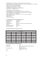
2.0 Technicalspecications
2.1 TechnicaldetailsInfrazonecontrol
• Delivery: Control panel with external display
• Dimensions external display (wxhxd): 160x98x43mm
• Dimensions switchbox (wxhxd): 376 x 300 x 120mm
• Weight switchbox: 4800 gram
• Weight display: 206 gram
• Protection class: IP20
• Mounting of display: built-in / wall installation
• Mounting of switchbox: built-on / wall mounting
• Number of zones: 3
• Number of Infra’s per zone: 6
• Temperature range: 2…40°C per 0,5°C.
• Operating options: Auto, continuous day, continuous night or continuous off
• Day-/night temperature monitoring with reading of the actual room temperature on the display
• Automatic switching between summer/winter time.
• Control: on/off, high/low or modulating
EN

4
• High/low control: Auto 1, 2 or 3K
• Time switch with week program (7 switch blocks)
• Overtime timer: 0-180 min. per zone
• Signaling of burner malfunction
• Reset option to release a burner malfunction per zone
• PIN security to modify for example switching times and temperatures
• Languages: English, French, German and Dutch
• Calibration temperature sensor: range from -3°C to +3°C per 0,5°C
• Power: 230Vac / 50Hz.
• Modbus TCP/IP
• Embedded webserver
2.2 Technicaldetailsforexternalglobesensor
• Type name : RSTF PT1000
• Article code : 06 29 082
• Resistance : PT1000
• Dimensions (wxhxd) : 85 x 85 x 27mm (40 mm incl. height external globe sensor)
• Weight : 42 gram
• Electrical connection : 0.14-1.5mm²
• Degree of protection : IP30
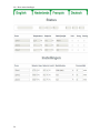
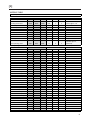
2.3 Externalglobesensorresistancetable
PT1000
°C Ω °C Ω °C Ω
- 50 803 + 20 1078 + 90 1347
- 40 843 + 30 1117 + 100 1385
- 30 882 + 40 1155 + 110 1423
- 20 922 + 50 1194 + 120 1461
- 10 961 + 60 1232 + 130 1498
0 1000 + 70 1271 + 140 1536
+ 10 1039 + 80 1309 + 150 1573
2.4 FactorysettingsZoneControlInfra
• Menu code : 1000
• Switching times : Block 1 MA, DI, WO, DO, VR 08:00-17:00 hrs
Block 2-7 off
• Room temperature : Day-time temperature 18°C
Night-time temperature 08°C
• Calibration : +0.0

5
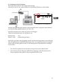
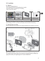
3.0 Installation
3.1 General
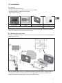
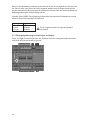
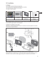
The Infra zone control exists of:
- A control box with in it connection terminals and controller;
- An external display to operate the controller;
- External globe sensor(s)
Control box Display Wall mounting plate External globe sensor
3003795 0629082
After unpacking, check the Infra zone control and (if ordered) external globe sensor for damage.
Check for correctness of the type/model and voltage.
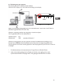
3.2 MountingInfrazonecontrol
Determine an appropriate place to mount the Infra zone control (control box, external display and
external globe sensor).
Place the external globe sensor in a draft-free area, within sight of the unit at a height of approx.
1,5 meter from the oor. Connect the sensor to the appropriate terminals in the Infra zone
control. See table on the next page for the correct cable diameter.
EN

6
Make sure the power is off before connecting the wiring. If this is not the case, the power must
be turned off before proceeding. When switching off the power of the device the technical book/
operation manual should be taken into account.
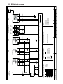
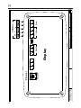
Connect the Infra zone control according to the electrical diagram at the end of this chapter.
Diameter Length
0.8mm
2
80 meter
1.0mm
2
100 meter It is recommended that a protected cable is used here.
1.5mm
2
150 meter
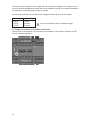
3.3 Checkconnectioncontrolleranddisplay
When the display and controller are connected properly through CAN-bus connections, the
lowest green LED will blink.

7
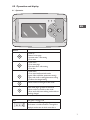
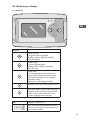
4.0 Operation and display
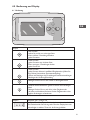
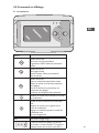
4.1 Operation
Buttons
• Scroll up
• Return to last page
• Increase value / edit setting
• Go to next
• Scroll down
• Go to next page
• Decrease value / edit setting
• Go to last
• Scroll down
• Go to next level/menu/edit mode
(open folder, subfolder, parameter setting)
• Open and conrm setting/parameter setting
• Conrm the change/setting.
• Move cursor to the right in edit mode
• Exit menu page / go back to last menu
• Move cursor to the left in edit mode
• (Press and hold) Leave editing mode without
making changes
LED LED green / orange / red
In case the red LED is lighting, it means an
Infra heater is in fault condition. Through the
display it can be seen in which zone this is.
EN

8
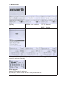
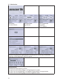
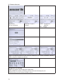
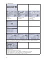
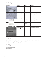
4.2 Menustructure
On: ame
Off: no ame
####: No sensor connected. 13.6 ºC: Measured
temperature.
8.0 ºC: Setpoint.
Set the desired day temperature, night temperature, calibration, modulating control, high/low
control for each zone seperately.
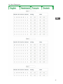
Clock program
Set the clock program for each zone.
It is possible to control 3 zones and have 7 timing functions per day.
Select the days, start and end times.

9
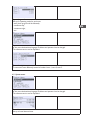
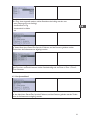
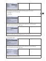
Operating mode
Set-up for operating mode for each zone
- auto (clock program will be followed),
- continuous day,
- continuous night,
- out
System menu
In this menu the date/time, language, IP address and password can be changed.
The software version can be requested.
Zone description
To name each zone differently instead of standard: zone 1, zone 2, zone 3.
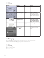
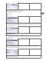
4.3 Systemmenu
System menu
In this menu the date/time, language, IP address and password can be changed.
The software version can be requested.
Date/time
Set-up of actual date and time.
EN

10
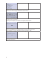
Language
Set-up for desired language (English, Nederlands, Français, Deutsch).
IP address
Set-up IP-address and Subnetmask
Note: After saving the IP address the controller will restart.
Change password
Set-up for changing the password to get access to the menu or to the webpage (standard
password is: 1000).
Software version
The actual software version.

11
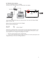
4.4 Operationwithacomputer
The unit can be operated using a PC or laptop.
Connect your PC or laptop by means of an Ethernet jack on the display.
Once you have connected both, start your internet browser* and enter the IP address (Default
address: 192.168.1.100).
When you have a connection a log in screen will appear.
Enter the username and password.
User name: user
Password: 1000 (factory setting) **
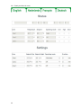
When the log in details have been correctly entered a tab with status/settings will appear in your
browser. Through the tabs at the top of the page the desired language can be chosen or a menu
can be opened to view or change the clock programm on screen.
* The factory advises Google Chrome or Mozilla Firefox.
** In case you have edited this through the display of the Infra zone control (menu/system menu/
change password) you must enter the changed password.
EN

12
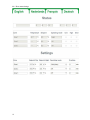
4.4.1 Menu status/settings

13
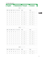
4.4.2 Menu clock program
EN

14
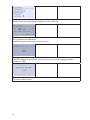
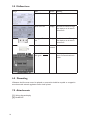
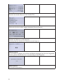
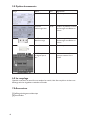
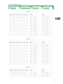
5.0 Malfunctions
Image Alert Where Meaning
#####ºC Display No sensor connected.
Reset error: No Display An Infra has a fault. Through
the display it can be seen in
which zone.
The right LED burns
red
Display An Infra has a fault. Through
the display it can be seen in
which zone.
------- ºC Internet
browser
No sensor connected.
Lowest LED doesn’t
ash green.
CANbus The display and the controller
aren’t connected with each
other.
6.0 Discarding
Whenever the Infra zone control is replaced or removed, it should be recycled or scrapped in
accordance with national regulations and/or local by-laws.
7.0 Attachments
[1] Wiring diagram display
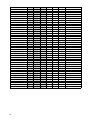
[2] Modbus-list

15
8.0 Electrical diagram

16

17
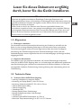
Lesen Sie dieses Dokument sorgfältig
durch, bevor Sie das Gerät installieren
Warnhinweis!
Fehlerhaft durchgeführte Installationen, Einstellungen, Änderungen, Reparaturen oder
Wartungsmaßnahmen können zu Sachschäden und Verletzungen führen. Alle Arbeiten müssen von
geprüften, qualizierten Fachleuten durchgeführt werden. Falls das Gerät nicht vorschriftsgemäß
aufgestellt wird, erlischt die Garantie.
Dieses Gerät ist nicht für den Gebrauch durch Personen (einschließlich Kindern) mit
verminderter körperlicher, Sinnes- oder geistiger Leistungsfähigkeit oder mangelnder Erfahrung
und mangelnden Kenntnissen bestimmt, sofern sie nicht unter Aufsicht stehen oder durch eine
Person, die für ihre Sicherheit verantwortlich ist, im Gebrauch des Geräts angeleitet werden.
Kinder müssen vom Gerät ferngehalten werden.
1.0 Allgemeines
1.1 Änderungenvorbehalten
Der Hersteller strebt eine kontinuierliche Verbesserung der Produkte an und behält sich das
Recht vor, ohne vorherige Mitteilung Änderungen an den technischen Daten vorzunehmen.
Die technischen Angaben werden als korrekt angenommen, bilden aber keine Grundlage für
einen Vertrag oder Gewährleistungsansprüche. Sämtliche Bestellungen werden unter den
Standardbedingungen unserer allgemeinen Verkaufs- und Lieferbedingungen (auf Anfrage erhältlich)
entgegengenommen.
1.2 AllgemeineWarnhinweise
Die Installation muss den geltenden landesweiten und örtlichen Bestimmungen entsprechen.
Lassen Sie die INFRA Zonen Regelung daher nur von fachkundigen und qualizierten Installateuren
unter Berücksichtigung der nationalen und internationalen Vorschriften installieren. Im Falle einer
unsachgemäßen Installation, Feinabstimmung, Änderung, Wartung oder Instandsetzung erlischt die
Gewährleistung.
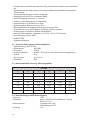
2.0 Technische Daten
2.1 TechnischeDatenINFRAZonenRegelung
• Lieferung: Schaltkasten mit externem Display
• Abmessung ext. Display (BxHxT): 160 x 98 x 43 mm
• Abmessung Schaltschrank (BxHxT): 376 x 300 x 120 mm
• Gewicht Schaltschrank: 4800 g
• Gewicht Display: 206 g
• Schutzklasse: IP20
• Montage Display: Einbau / Wandmontage
• Montage Schaltschrank: Aufbau / Wandmontage
• Zonenanzahl: 3
• maximale Anzahl INFRA-Dunkelstrahler pro Zone: 6
• Bereich der Temperatureinstellung: 2 bis 40°C in 0,5°C Schritten
DE

18
• Betriebsmodus: automatisch, kontinuierlich bei Tag, kontinuierlich bei Nacht oder kontinuierlich
aus
• Tag-/Nachttemperatur Überwachung mit Anzeige und ablesen der aktuellen Raumtemperatur
auf dem Display
• automatische Anpassung der Sommer-/Winterzeit
• Regelung: Ein/Aus, Hoch/Tief, modulierend (PWM)
• Hoch/Tief Regelung: automatisch 1, 2 oder 3K
• Schaltuhr mit Wochenprogramm (7 Schaltblöcke)
• Überstundentimer: 0-180 Minuten pro Zone
• Signalisierung einer Brennerstörung pro Zone
• Resetmöglichkeit zur Entriegelung einer Brennerstörung pro Zone
• Sicherheitscode um u.a. die Schaltzeiten und Temperaturen zu verändern
• Sprachen: Englisch, Französisch, Deutsch, Niederländisch
• Justierung Temperaturfühler: regulierbar von -3°C bis +3°C in 0.5°C Schritten
• Stromversorgung: 230 Vac/ 50Hz
• Modbus TCP/IP
• eingebauter Webserver
2.2 TechnischeDatenexternerSchwarzkugelfühler
• Typenbezeichnung : RSTF PT1000
• Artikelnummer : 06 29 082
• Widerstand : PT1000
• Abmessung (BxHxT) : 85 x 85 x 27mm (40 mm inkl. Höhe des Schwarzkugelfühlers)
• Gewicht : 42 g
• Stromanschluss : 0.14-1.5mm²
• Schutzklasse : IP30
2.3 Widerstandstabelle(externer)Schwarzkugelfühler
PT1000
°C Ω °C Ω °C Ω
- 50 803 + 20 1078 + 90 1347
- 40 843 + 30 1117 + 100 1385
- 30 882 + 40 1155 + 110 1423
- 20 922 + 50 1194 + 120 1461
- 10 961 + 60 1232 + 130 1498
0 1000 + 70 1271 + 140 1536
+ 10 1039 + 80 1309 + 150 1573
2.4 WerkseinstellungenINFRAZonenRegelung
• Menücode : 1000
• Schaltzeiten : Block 1 MO, DI, MI, DO, FR 08:00 bis 17:00 Uhr
Block 2 bis 7 aus
• Raumtemperatur : Tagestemperatur 18°C
Nachttemperatur 08°C
• Justierung : +0.0

19
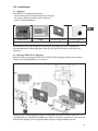
3.0 Installation
3.1 Allgemein
Die INFRA Zonen Regelung besteht aus:
- einen Schaltschrank mit Anschlussklemmen und Regler;
- ein externes Display zur Bedienung der Regelung;
- externer Schwarzkugelfühler
Schaltschrank Display Wandmontageplatte Schwarzkugelfühler
3003795 0629082
Kontrollieren Sie nach dem Auspacken die INFRA Zonen Regelung und den mitgelieferten
Schwarzkugelfühler auf Beschädigungen. Prüfen Sie den Typen/das Model und die elektrische
Spannung.
3.2 MontageINFRAZonenRegelung
Bestimmen Sie einen geeigneten Platz um die INFRA Zonen Regelung (Schaltschrank, externes
Display und Schwarzkugelfühler) zu montieren.
Bringen Sie den Schwarzkugelfühler zugfrei, in Sichtweite des Gerätes auf einer Höhe von ca. 1,5
m ab Fußboden, an. Schließen Sie außerdem den Fühler an die dafür vorgesehenen Klemmen in der
INFRA Zonen Regelung an. Die folgende Tabelle zeigt die richtigen Kabelquerschnitte.
DE

20
Bevor Sie die Verkabelung vornehmen, prüfen Sie bitte ob der Strom abgestellt ist. Falls dies nicht
der Fall sein sollte, muss zuerst der Strom abgestellt werden, bevor Sie weitermachen können.
Bei dem Ausstellen des Stroms und das Anschließen des Gerätes muss das Technische Handbuch/
Bedienungsanleitung des Gerätes befolgt werden.
Schließen Sie die INFRA Zonen Regelung entsprechend der elektrischen Schaltpläne an, welche
hinten im Technischen Handbuch zu nden sind.
Durchmesser Länge
0.8mm
2
80 Meter
1.0mm
2
100 Meter Es wird angeraten hierfür ein separates Kabel zu
1.5mm
2
150 Meter verwenden.
3.3 ÜberprüfungVerbindungzwischenReglerundDisplay
Wenn der Regler und das Display über den CAN-bus Anschluss richtig miteinander verbunden
sind, blinkt das unterste Lämpchen grün auf.
Seite wird geladen ...
Seite wird geladen ...
Seite wird geladen ...
Seite wird geladen ...
Seite wird geladen ...
Seite wird geladen ...
Seite wird geladen ...
Seite wird geladen ...
Seite wird geladen ...
Seite wird geladen ...
Seite wird geladen ...
Seite wird geladen ...
Seite wird geladen ...
Seite wird geladen ...
Seite wird geladen ...
Seite wird geladen ...
Seite wird geladen ...
Seite wird geladen ...
Seite wird geladen ...
Seite wird geladen ...
Seite wird geladen ...
Seite wird geladen ...
Seite wird geladen ...
Seite wird geladen ...
Seite wird geladen ...
Seite wird geladen ...
Seite wird geladen ...
Seite wird geladen ...
Seite wird geladen ...
Seite wird geladen ...
Seite wird geladen ...
Seite wird geladen ...
Seite wird geladen ...
Seite wird geladen ...
Seite wird geladen ...
Seite wird geladen ...
Seite wird geladen ...
Seite wird geladen ...
Seite wird geladen ...
Seite wird geladen ...
Seite wird geladen ...
Seite wird geladen ...
Seite wird geladen ...
Seite wird geladen ...
Seite wird geladen ...
Seite wird geladen ...
-
 1
1
-
 2
2
-
 3
3
-
 4
4
-
 5
5
-
 6
6
-
 7
7
-
 8
8
-
 9
9
-
 10
10
-
 11
11
-
 12
12
-
 13
13
-
 14
14
-
 15
15
-
 16
16
-
 17
17
-
 18
18
-
 19
19
-
 20
20
-
 21
21
-
 22
22
-
 23
23
-
 24
24
-
 25
25
-
 26
26
-
 27
27
-
 28
28
-
 29
29
-
 30
30
-
 31
31
-
 32
32
-
 33
33
-
 34
34
-
 35
35
-
 36
36
-
 37
37
-
 38
38
-
 39
39
-
 40
40
-
 41
41
-
 42
42
-
 43
43
-
 44
44
-
 45
45
-
 46
46
-
 47
47
-
 48
48
-
 49
49
-
 50
50
-
 51
51
-
 52
52
-
 53
53
-
 54
54
-
 55
55
-
 56
56
-
 57
57
-
 58
58
-
 59
59
-
 60
60
-
 61
61
-
 62
62
-
 63
63
-
 64
64
-
 65
65
-
 66
66


Mark Infra zone control Technical Manual
- Typ
- Technical Manual
- Dieses Handbuch eignet sich auch für
in anderen Sprachen
- English: Mark Infra zone control
- français: Mark Infra zone control
- Nederlands: Mark Infra zone control
Verwandte Artikel
Andere Dokumente
-
OJ Electronics OJ-Zone-Module-M Bedienungsanleitung
-
 OJ OJ-Zone-Module-A Bedienungsanleitung
-
Sharp Actius PC-UM20 Benutzerhandbuch
-
-
Caliber WLC001 Bedienungsanleitung
-
Trane WFE 3 Technical Manual
-
-
Jablocom EYE-02 Benutzerhandbuch
-
REMEHA iSense Benutzerhandbuch
-
 METREL EDA1131 Bedienungsanleitung

