
A 1
B
3
2
1
3
42
8012245.U894 0310 GO KE
UF3
Subject to change without notice
Irrtümer und Änderungen vorbehalten
Sujet à modification sans préavis
Alterações poderão ser feitas sem prévio aviso
Med forbehold for ændringer og fejl
Contenuti soggetti a modifiche senza preavviso
Wijzigingen en correcties voorbehouden
Sujeto a cambio sin previo aviso
1
L+
Q
P
M
Q
N
4
3
2
brn
blk
blu
wht
AA
AA
A (mm)
BB
BB
B (mm)
CC
CC
C (mm)
UF3 3 69 14
–
3s
–
6s
+
–
4
%a
%b
6
10
19
7
B
8
22,5
6
16
A
22,5
C
11
4,2
PNP/NPN
L
D
5
+
–
+
–
3 s
+
–
+
–
3 s
Australia
Phone +61 3 9497 4100
E-Mail: [email protected]
Belgium/Luxembourg
Phone +32 (0)2 466 55 66
E-Mail: [email protected]
Brasil
Phone +55 11 3215-4900
E-Mail: [email protected]
Ceská Republika
Phone +420 2 57 91 18 50
E-Mail: [email protected]
China
Phone +852-2763 6966
E-Mail: [email protected]
Danmark
Phone +45 45 82 64 00
E-Mail: [email protected]
Deutschland
Phone +49 211 5301-301
E-Mail: [email protected]
España
Phone +34 93 480 31 00
E-Mail: [email protected]
France
Phone +33 1 64 62 35 00
E-Mail: [email protected]
Great Britain
Phone +44 (0)1727 831121
E-Mail: [email protected]
India
Phone +91–22–4033 8333
E-Mail: [email protected]
Israel
Phone +972-4-999-0590
E-Mail: [email protected]
Italia
Phone +39 02 27 43 41
E-Mail: [email protected]
Japan
Phone +81 (0)3 3358 1341
E-Mail: [email protected]
Nederlands
Phone +31 (0)30 229 25 44
E-Mail: [email protected]
Norge
Phone +47 67 81 50 00
E-Mail: [email protected]
Österreich
Phone +43 (0)22 36 62 28 8-0
E-Mail: [email protected]
Polska
Phone +48 22 837 40 50
E-Mail: [email protected]
Republic of Korea
Phone +82-2 786 6321/4
E-Mail: info@sickkorea.net
Republika Slovenija
Phone +386 (0)1-47 69 990
E-Mail: [email protected]
România
Phone +40 356 171 120
E-Mail [email protected]
Russia
Phone +7 495 775 05 34
E-Mail info@sick-automation.ru
Schweiz
Phone +41 41 619 29 39
E-Mail: [email protected]
Singapore
Phone +65 6744 3732
E-Mail: [email protected]
Suomi
Phone +358-9-25 15 800
E-Mail: [email protected]
Sverige
Phone +46 10 110 10 00
E-Mail: [email protected]
Taiwan
Phone +886 2 2375-6288
E-Mail: [email protected]
Türkiye
Phone +90 216 587 74 00
E-Mail: [email protected]
United Arab Emirates
Phone +971 4 8865 878
E-Mail: [email protected]
USA/Canada/México
Phone +1(952) 941-6780
E-Mail: [email protected]
BZ int35
More representatives and agencies at www.sick.com
+
–
+
–
A!
ENGLISH
Ultrasonic Fork Sensor
Operating Instructions
Safety Specifications
‡ Read the operating instructions before starting operation.
‡ Connection, assembly, and settings only by competent
technicians.
‡ Protect the device against moisture and soiling when
operating.
‡ No safety component in accordance with EU machine
guidelines.
Proper Use
The ultrasonic fork sensor UF is a sensor which operates
using a transmission and reception unit. It is used for non-
contact detection of labels, double-sheets and tape.
Starting Operation
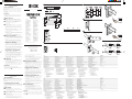
1 L: light-switching, output (Q) switches to the carrier
material (1 object). D: dark-switching, output (Q)
switches to the label and carrier material (2 objects).
2 Connect and secure cable receptacle tension-free. The
following apply for connection in B: brn=brown,
blu=blue, blk=black, wht=white.
Connect cables.
3 Mount sensor with mounting holes to a suitable fixture
and align it roughly.
Move the material to be scanned in a taut state and
flutter-free through the fork opening. If necessary, move
the material to be scanned over the lower side of the
fork.
Connect sensor to operating voltage (see type label); the
LED signal strength indicator must light.
The material speed must be zero (machine is idle).
Setting the sensitivity:
Press the “+” or “–” button for a short time; slow setting.
The LED signal strength indicator (red) lights each time
you press the button.
Press the “+” or “–” button continually; fast setting. The
LED signal strength indicator (red) blinks.
4
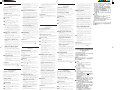
Setting in L mode: light-switching Setting in L mode: light-switching
Setting in L mode: light-switching Setting in L mode: light-switching
Setting in L mode: light-switching (gap detection)
1. Position the label with the carrier material between the
active area of the fork sensor. Adjust switching point using
the “–” button until the switching output display (yellow)
turns off.
2. Position carrier material. The LED signal strength
indicator (yellow) must light again. If this is not the case,
increase the sensitivity using the “+” button until the
switching threshold is set correctly.
Setting in D mode: dark-switching Setting in D mode: dark-switching
Setting in D mode: dark-switching Setting in D mode: dark-switching
Setting in D mode: dark-switching (label detection)
1. Position the carrier material between the active area of
the fork sensor. Adjust switching point using the “+”
button until the switching output display (yellow) turns
off.
2. Position the label with the carrier material between the
active area of the fork sensor. The LED signal strength
indicator (yellow) must light again. If this is not the case,
decrease the sensitivity using the “–” button until the
switching threshold is set correctly.
Setting when there is a slight signal differenceSetting when there is a slight signal difference
Setting when there is a slight signal differenceSetting when there is a slight signal difference
Setting when there is a slight signal difference
(description in light-switching mode)
1. Position the label with the carrier material between the
active area of the fork sensor. Adjust sensitivity with “+”
or “–” button just until the sensor stops switching.
2. Position the carrier material between the active area of
the fork sensor. Reduce the switching point with the “–”
button just until the sensor does not switch anymore.
Count the number of button clicks.
3. Setting: reset the switching point half back and check
whether the sensor switches reliably.
5
Locking/unlockingLocking/unlocking
Locking/unlockingLocking/unlocking
Locking/unlocking
Press the “+” and “–” buttons simultaneously for 3 s. The
LED signal strength indicator (red) switches off. Leave
button off. The LED signal strength indicator (red) lights on.
The dark/light switching can be set if you press the “+”
and “–” buttons simultaneously (6 s).
Switch over: the switching output (yellow) changes, and
the LED signal strength indicator (red) blinks slowly.
Maintenance
SICK sensors do not require any maintenance.
We recommend to check the screw connections and plug-in
connections at regular intervals. The lower side can be
removed for cleaning (
A!
).
DEUTSCH
Ultraschall-Gabelsensor
Betriebsanleitung
Sicherheitshinweise
‡ Vor der Inbetriebnahme die Betriebsanleitung lesen.
‡ Anschluss, Montage und Einstellung nur durch Fachpersonal.
‡ Gerät bei Inbetriebnahme vor Feuchte und Verunreinigung
schützen.
‡ Kein Sicherheitsbauteil gemäß EU-Maschinenrichtlinie.
Bestimmungsgemäße Verwendung
Der Ultraschall-Gabelsensor UF ist ein Sensor, der mit einer
Sende- und Empfangseinheit arbeitet. Er wird zum berührungs-
losen Erfassen von Etiketten, Doppelbögen und Klebestreifen
eingesetzt.
Inbetriebnahme
1 L: hellschaltend, Ausgang (Q) schaltet auf das Träger-
material (1 Objekt).
D: dunkelschaltend, Ausgang (Q) schaltet auf das Etikett
und Trägermaterial (2 Objekte).
2 Leitungsdose spannungsfrei aufstecken und festschrauben.
Für Anschluss in B gilt: brn=braun, blu=blau, blk=schwarz,
wht=weiß.
Leitungen anschließen.
3 Sensor mit Befestigungsbohrungen an geeignete Halter
montieren und ausrichten.
Das Tastmaterial im gespannten Zustand und flatterfrei
durch die Gabelöffnung bewegen. Ggf. Tastmaterial über
den unteren Schenkel der Gabel bewegen.
Sensor an Betriebsspannung legen (s. Typenaufdruck);
Funktionsanzeige muss leuchten.
Materialgeschwindigkeit gleich Null (Maschine steht).
Einstellung der Empfindlichkeit:
„+“ oder „–“-Taste kurz betätigen, langsame Einstellung.
Funktionsanzeige (rot) leuchtet pro Tastendruck.
„+“ oder „–“-Taste dauerhaft betätigen, schnelle
Einstellung. Funktionsanzeige (rot) blinkt.
4
Einstellung im Modus L: hellschaltend Einstellung im Modus L: hellschaltend
Einstellung im Modus L: hellschaltend Einstellung im Modus L: hellschaltend
Einstellung im Modus L: hellschaltend (Lückenerkennung)
1. Etikett mit Trägermaterial zwischen der aktiven Fläche
des Gabelsensors positionieren. Mit der „–“-Taste
Schaltpunkt einstellen, bis Schaltausgangsanzeige (gelb)
erlischt.
2. Trägermaterial positionieren. Die Schaltausgangsanzeige
(gelb) muss wieder aufleuchten; ist dies nicht der Fall,
Empfindlichkeit mit „+“-Taste erhöhen, bis die Schalt-
schwelle korrekt eingestellt ist.
Einstellung im Modus D: dunkelschaltendEinstellung im Modus D: dunkelschaltend
Einstellung im Modus D: dunkelschaltendEinstellung im Modus D: dunkelschaltend
Einstellung im Modus D: dunkelschaltend (Etiketten-
erkennung)
1. Trägermaterial zwischen der aktiven Fläche des
Gabelsensors positionieren. Mit der „+“-Taste Schaltpunkt
einstellen bis Schaltausgangsanzeige (gelb) erlischt.
2. Etikett mit Trägermaterial zwischen der aktiven Fläche
des Gabelsensors positionieren. Die Schaltausgangsan-
zeige (gelb) muss wieder aufleuchten; ist dies nicht der
Fall, Empfindlichkeit mit „–“-Taste veringern, bis die
Schaltschwelle korrekt eingestellt ist.
Einstellung bei geringem SignalunterschiedEinstellung bei geringem Signalunterschied
Einstellung bei geringem SignalunterschiedEinstellung bei geringem Signalunterschied
Einstellung bei geringem Signalunterschied (Beschrei-
bung im Modus hellschaltend)
1. Etikett mit Trägermaterial zwischen der aktiven Fläche
des Gabelsensors positionieren. Empfindlichkeit mit +“-
oder „–“-Taste anpassen, bis der Sensor gerade nicht
mehr schaltet.
2. Trägermaterial zwischen der aktiven Fläche des
Gabelsensors positionieren. Mit der „–“-Taste Schaltpunkt
senken, bis der Sensor nicht mehr schaltet. Anzahl der
Tastenklicks zählen.
3. Einstellen: Den Schaltpunkt zur Hälfte wieder zurück-
stellen und prüfen, ob der Sensor sicher schaltet.
5
VV
VV
V
erer
erer
er
rr
rr
r
iegelung/Entriegelung/Entr
iegelung/Entriegelung/Entr
iegelung/Entr
iegelung:iegelung:
iegelung:iegelung:
iegelung:
„+“- und „–“-Tasten gleichzeitig drücken (3 s). Die
Funktionsanzeige (rot) erlischt. Tasten loslassen. Die
Funktionsanzeige (rot) leuchtet.
Durch gleichzeitiges Drücken der „+“- und „–“-Tasten
(6 s), kann die Hell/Dunkelschaltung eingestellt werden.
Umschaltung: Die Schaltausgangsanzeige (gelb) wechselt
den Status und die Funktionsanzeige (rot) blinkt langsam.
Wartung
SICK-Sensoren sind wartungsfrei. Wir empfehlen, in regelmäßi-
gen Abständen die Verschraubungen und Steckverbindungen
zu überprüfen. Der untere Schenkel kann zur Reinigung entfernt
werden (
A!
).
Ba_UF3_KV2_0.pmd 23.04.2010, 11:011
Seite wird geladen ...
-
 1
1
-
 2
2


in anderen Sprachen
- English: SICK SENSICK UF3 Operating instructions
- français: SICK SENSICK UF3 Mode d'emploi
- español: SICK SENSICK UF3 Instrucciones de operación
- italiano: SICK SENSICK UF3 Istruzioni per l'uso
- Nederlands: SICK SENSICK UF3 Handleiding
- português: SICK SENSICK UF3 Instruções de operação
- dansk: SICK SENSICK UF3 Betjeningsvejledning
Verwandte Artikel
-
SICK SENSICK WF 3T/5T Bedienungsanleitung
-
-
-
-
-
-
-
-
-