FMS FMM113P Bedienungsanleitung
- Kategorie
- Ferngesteuertes Spielzeug
- Typ
- Bedienungsanleitung
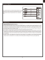
Dieses Handbuch eignet sich auch für

70mm A-10
Thunderbolt II V2
REALISTIC STABLE
Retracts & Flaps installed Smooth flying performance
RIGID
Strong durable EPO material
FMSMODEL.COM

WARNING: Read the ENTIRE instruction manual to become familiar with the features of the product before operating.
Failure to operate the product correctly can result in damage to the product,personal property and cause serious injury.
This is a sophisticated hobby product and NOT a toy. It must be operated with caution and common sense and failure to do so
could result in injury or damage to the product or other property. This product is not intended for use by children without direct
adult supervision.
This manual contains instructions for safety operation and maintenance. It is essential to read and follow all the instructions and
warnings in the manual prior to assembly, setup or use, in order to operate and avoid damage or serious injury.
WARNING
As the user of this product, you are solely responsible for operating in a manner that does not endanger yourself and others or
result in damage to the product or the property of others. This model is controlled by a radio signal subject to interference from
many sources outside your control. This interference can cause momentary loss of control so it is advisable to always keep a
safe distance in all directions around your model, as this margin will help avoid collisions or injury.
Age Recommendation: Not for children under 14 years. This is not a toy.
·Never operate your model with low transmitter batteries.
·Always operate your model in an open area away from cars, traffic or people.
·Avoid operating your model in the street where injury or damage can occur.
·Never operate the model in populated areas for any reason.
·Carefully follow the directions and warnings for this and any optional support equipment you use (chargers,rechargeable
battery packs, etc.)
·Keep all chemicals, small parts and anything electrical out of the reach of children.
·Moisture causes damage to electronics. Avoid water exposure to all equipment not specifically designed and protected for this
purpose.
·Never lick or any place of any your model in your mouth as it could cause serious injury or even death.
Lithium Polymer (Li-Po) Battery Warning
CAUTION: Always follow the manufacturer’s instructions for safe use and disposal of batteries. Fire, property
damage, or serious injury can result from the mishandling of Li-Po batteries.
By handling, charging or using a Li-Po Battery you assume all risks associated with lithium batteries.
If at any time the batteries begin to swell or balloon, discontinue use immediately!
Always store the batteries at room temperature in a dry area to extend the life of the battery. Always transport
or temporarily store the battery in a temperature range of 40-120F. Do not store the battery or model in a car or in direct sunlight.
If stored in a hot car, the battery can be damaged or even catch fire.
Never use a Ni-Mh Charger to charge Li-Po Batteries. Failure to charge the battery with a Li-Po compatible charger
may cause fire resulting in personal injury and property damage.
Never discharge Li-Po Cells below 3V.
Never leave charging batteries unattended.
Never charge damaged batteries.
Charging the Flight Battery Warning
Use a battery charger that is designed to safely charge the Li-Po Battery. Read the charger instructions care
fully before use. When charging the battery, make certain the battery is on a heat resistant surface. It is also highly
recommended to place the Li-Po Battery inside a fire resistant charging bag readily available at hobby shops or
online.
p w

3
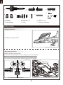
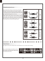
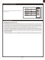
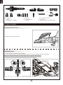
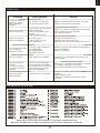
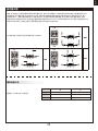
Before assembly, please inspect the contents of the kit. The
photo below details the contents of the kit with labels. If any
parts are missing or defective, please identify the name or
part number (refer to the spare parts list near the end of the
manual) then contact your local shop or email us: support
Kit contents
Introduction
New release: FMS A-10 Thunderbolt II “Warthog”V2 In 2017, FMS announced its flagship aircraft- the A-10 Thunderbolt II. Known
for its impeccable scale features and awesome performance, the “Warthog”is truly a favorite amongst pilots and spectators alike.
To make the best even better, FMS has dedicated significant engineering effort in building upon the first generation A-10, making
evolutionary design and performance improvements to create the A-10 V2.Retaining features such as the screw-together airframe,
ball-linked control surfaces and high strength spar system, the A-10 V2 comes together just as easily its predecessor. Scale details
remain impeccable- realistic rivets, panel lines, removable bombs and rockets and realistic absorbing CNC landing gear, just to
name a few.Built upon these great features, the A-10 V2 receives ten major structural, electronic and scale improvements:
1.Improved ESC: The dual 70A ESCs are uprated to dual Hobbywing 80A ESCs, with an external 8A BEC for bulletproof
performance.
2.Upgraded servos: Elevator and Rudder servos have been upgraded to 23g metal geared servos from the original 17g metal
geared units- meaning more torque for the control surfaces giving even better performance.
3.Precision landing gear design: The nose landing gear has been redesigned to minimize play- ensuring the assembly tracks
straight and true even at high speeds.
4.Improved connectors: ‘soft’ connector design significantly increases the reliability of the wing quick release system.
Wingspan: 1500mm(59.1in)
Overall length: 1368mm(53.9in)
Flying weight: ~ 4100g
Motor size: 2860-KV1850
Wing load: 113.2g/dm²(0.26oz/in²)
Wing area: 36.2dm²(561sq.in)
ESC: 80A ESC X 2 with 8A BEC
Servo: 13g metal x 5 23g metal x 4
Recommended battery: 22.2V 5000mAh 45C
Specifications
@fmsmodel.com
Introduction
Kit contents
Model assembly
Battery installation
Receiver diagram
Preflight check
Clevis installation
Control horn and servo arm settings
Center of gravity(CG)
Before flying the model
Flying course
Troubleshooting
Spare parts list content
T
Table of contents
·····························································
·····
3
·························································3
·······················································4
············································· ········ 8
·········································
··
········ 9
································
·····························
··
·····
·····
·····
9
····················································11
·················
··············································· 11
············································12
·························································12
······················································13
············································13
11
5.Increased elevator travel: giving pilots more precision and control authority
6.Improved tires: an improved, more durable compound extends
the service life of the landing gear wheels, even in rough field
operations.
7.Robust canopy latch: extended pin on the canopy latch reduces the possibility of an accidental canopy release in flight.
8.Enlarged battery bay: now fits two 6S 3300mAh Lipos, for significantly increased flight times!
9.New trim scheme: even more attractive trim than the original!
10.New scale pilot
Features:
• Dual 70mm inrunner 12 bladed EDFs and Hobbywing 80A ESCs provide ample thrust.
• Highly realistic scale features: Rivets, panel lines, CNC shock absorbing landing gears, removable bombs and rocket pods,
scale pilot figure etc.
• Ultra bright LED light system.
• Electronic retracts with over current protection.
• Large diameter bearings in the landing gear allow the A-10 V2 to roll smoothly over rough terrain.
• Preinstalled ball-linked control horns for accurate and precise movements.
Feel the FMS difference! No detail was overlooked in creating the A-10 V2! Feel the power and turn every head at the flying field
with your very own “Warthog”.

4
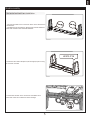
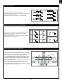
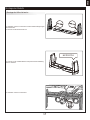
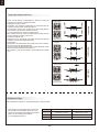
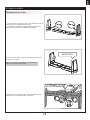
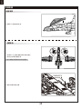
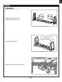
Canopy installation
Main wing installation
Model assembly
1.Install the canopy as shown
3.Secure the left and right wings to the fuselage using the 4 screws included.
1.Slide the wing spars into the fuselage.
2.Install the left and right wing halves over the wing spars and into the wing slots
precisely and firmly.
HKM3.0*20
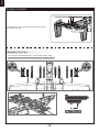
A: Fuselage
B: Main wing
C: Horizontal stabilizer
D: Vertical stabilizers
E: Missile set
F: Canopy
A.
B.
C.
F.
G.
H.
I.
D.
E.
G: Carbon fiber spars
H: Screws
I : Ventral fins and pitot tubes
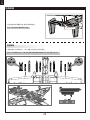
Notice:The connectors on both sides should be attached

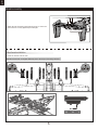
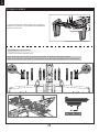
Horizontal and stabilizers installation
1. Connect the rudder servo connectors to the servo extensions in
the elevator .
2. Complete the tail assembly by attaching the vertical stabilizers
to the slots located on the horizontal stabilizer.
3.Secure the two vertical tail pieces (left and right) in place using
the 4 screws included.
4.Connect the elevator servo connectors and rudder servo
connectors to the servo extensions in the fuselage.
5
Model assembly
HKM3.0*16

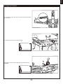
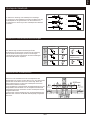
Missile set installation
5.Attach the tail assembly to the fuselage using 4 screws. The
screws must be securely tightened prior to flight.
6
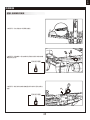
Model assembly
1. Slide the missiles into the rails.
Note:the missile rails are angled differently due to the shape of the wing structure
HKM3.0*20

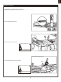
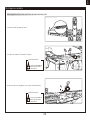
ventral fins and pitot tube installation
1.Screw the pitot tube in place.
2.Slide ventral fins into the rails.
Required Adhesives:
Foam Safe Medium CA
Required Adhesives:
Foam Safe Medium CA
7
Model assembly
3. Insert the plastic part by CA as shown.

1. Remove the canopy.
2. Remove the hook and loop tape from the fuselage. Apply the
looped surface to the battery.
3. Install the battery into the fuselage- securing it with the
preinstalled battery straps.
Note: The weight of each battery may vary due to different
manufacturing techniques. Move the battery fore or aft to
achieve the optimal center of gravity.
Battery installation
Required Adhesives:
Foam Safe Medium CA
4.Insert the foaming part by CA as shown.
8
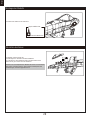
Model assembly

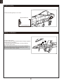
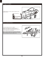
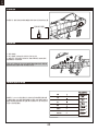
Important ESC and model information
The ESC included with the model has a safe start. If the motor battery is connected to the ESC and the throttle stick is not in
the low throttle or off position, the motor will not start until the throttle stick is moved to the low throttle or off position. Once the
throttle stick is moved to the low throttle or off position, the motor will emit a series of beeps. Several beeps with the same tune
means the ESC has detected the cells of the battery. The count of the beeps equals the cells of the battery. The motor is now
armed and will start when the throttle is moved.
The motor and ESC come pre-connected and the motor rotation should be correct. If for any reason the motor is rotating in the
wrong direction, simply reverse two of the three motor wires to change the direction of rotation.
The motor has an optional brake setting. The ESC comes with brake switched off and we recommend that the model be flown
with the brake off. However, the brake could be accidentally switched on if the motor battery is connected to the ESC while the
throttle stick is set at full throttle. To switch the brake off, move the throttle stick to full throttle and plug in the motor battery. The
motor will beep one time. Move the throttle stick to low throttle or the off position. The motor is ready to run and the brake will
be switched off.
Battery Selection and Installation. We recommend the 22.2V 5000mAh 45C Li-Po battery. If using another battery, the battery
must be at least a 22.2V 5000mAh 45C battery. Your battery should be approximately the same capacity, dimension and
weight as the 22.2V 5000mAh 45C Li-Po battery to fit the fuselage without changing the center of gravity significantly.
1.
2.
3.
4.
9
Receiver diagram
Preflight check
The cables from the servo connector board should be connected
to your receiver in the order shown. Note that the LEDs can be
powered by any spare channel on the receiver. Tuck the wire
leads into the recessed cavity towards the rear of the battery
hatch.
5
Gear
Gear
Spare
5
Spare

Transmitter and model setup
Before getting started, bind your receiver with your transmitter.
Please refer to your transmitter manual for proper operation.
CAUTION: To prevent personal injury, DO NOT install the propel-
ler assembly onto the motor shaft while testing the control surfac-
es. DO NOT arm the ESC and do not turn on the transmitter until
the Transmitter Manual instructs you to do so.
Tips: Make sure all control sticks on your radio are in the neutral
position (rudder, elevator, ailerons) and the throttle is in the OFF
position. Make sure both ailerons move up and down (travel) the
same amount. This model tracks well when the left and right
ailerons travel the same amount in response to the control stick.
Move the controls on the transmitter to make sure the aircraft
control surface moves correctly. See diagrams right.
10
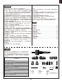
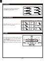
Control throws
The suggested control throw setting for the A-10 Thunderbolt II V2 are as follows (dual rate setting):
Tips: On the first flight, fly the model in low rate.
The first time you use high rates, be sure to fly at
low to medium speeds. High rate, as listed, is only
for EXTREME maneuvering.
Aileron
Bank left
Bank right
Elevator
Climb
Descend
Steering Rudder
Steer left
Steer right
20 15
18
15
23
20

11
More control throw
Less control throw
Horns Arms
a.
b.
c.
d.
e.
f.
Clevis installation
1.Pull the tube from the clevis to the linkage.
2.Carefully spread the clevis, then insert the clevis pin into the
desired hole in the control horn.
3.Move the tube to hold the clevis on the control horn.
Control horn and servo arm settings
The table shows the factory settings for the control horns
and servo arms. Fly the aircraft at the factory settings
before making changes.
After flying,you may choose to adjust the linkage positions
for the desired control response.
ElevatorRudderAilerons
Check the C.G. (Center of gravity)
When balancing your model, adjust the battery as necessary
so the model is level or slightly nose down. This is the correct
balance point for your model. After the first flights, the CG
position can be adjusted for your personal preference.
1. The recommended Center of Gravity (CG) location for your
model is(80-85mm) from the leading edge of the main wing
(as shown) with the battery pack installed. Mark the location of
the CG on top of the wing.
2. When balancing your model, support the plane at the marks
made on the bottom of the main wing with your fingers or a
commercially available balancing stand. This is the correct
balance point for your model. Make surethe model is assembled
and ready for flight before balancing.
80-85mm

Take off
Maintenance
Landing
Find a suitable flying site
Perform the range check for your plane
Monitor your flight time
Find a flying site clear of buildings, trees, power lines and
other obstructions. Until you know how much area will be
required and have mastered flying your plane in confined
spaces, choose a site which is at least the size of two to three
football fields - a flying field specifically for R/C planes is best.
Never fly near people - especially children, who can wander
unpredictably.
As a precaution, an operational ground range test should be
performed before the first flight each time you go out.
Performing a range test is a good way to detect problems
that could cause loss of control such as low batteries, defective
or damaged radio components, or radio interference. This
usually requires an assistant and should be done at the actual
flying site you will be using.
First turn on the transmitter, then install a fully-charged battery
into the fuselage. Connect the battery and install the hatch.
Remember, use care not to bump the throttle stick. Otherwise,
the propeller/fan will turn and possibly cause damage or injury.
Note: Please refer to your Transmitter Manual that came with
your radio control system to perform a ground range check. If
the controls are not working correctly or if anything seems
wrong, do not fly the model until you correct the problem. Make
certain all the servo wires are securely connected to the
receiver and the transmitter batteries have a good connection.
Monitor and limit your flight time using a timer (such as on a
wristwatch or in your transmitter if available). When the
batteries are getting low you will usually notice a performance
drop before the ESC cuts off motor power, so when the plane
starts flying slower you should land. Often (but not always)
power can be briefly restored after the motor cuts off by
holding the throttle stick all the way down for a few seconds.
To avoid an unexpected dead-stick landing on your first flight,
set your timer to a conservative 4 minutes. When your alarm
sounds you should land right away.
12
Before flying the model
Flying course
While applying power, slowly steer to keep the model straight.
The model should accelerate quickly. As the model gains flight
speed you will want to climb at a steady and even rate. It will
climb out at a nice angle of attack (AOA).
Flying
Always choose a wide-open space for flying your plane. It is
ideal for you to fly at a sanctioned flying field. If you are not
flying at an approved site always avoid flying near houses,
trees, wires and buildings. You should also be careful to avoid
flying in areas where there are many people, such as busy
parks, schoolyards, or soccer fields. Consult laws and
ordinances before choosing a location to fly your aircraft. After
takeoff, gain some altitude. Climb to a safe height before trying
technical manoeuvres, including high speed passes, inverted
flight, loops, and point rolls.
Land the model when you hear the motor pulsing (LVC) or if
you notice a reduction in power. If using a transmitter with a
timer, set the timer so you have enough flight time to make
several landing approaches.
The model’s three point landing gear allows the model to land
on hard surfaces. Align model directly into the wind and fly
down to the ground. Fly the airplane down to the ground using
1/4-1/3 throttle to keep enough energy for proper flare. Before
the model touches down, always fully decrease the throttle to
avoid damaging the propeller or other components. The key to
a great landing is to manage the power and elevator all the
way to the ground and set down lightly on the main landing
gear. After a few flights you will find the model can be set down
lightlyon the mains and you can hold the nose wheel off
balancing themodel on the mains until it slows and gently
settles the nose.
Repairs to the foam should be made with foam safe adhesives
such as hot glue, foam safe CA, and 5min epoxy. When parts
are not repairable, see the Spare Parts List for ordering by item
number.
Always check to make sure all screws on the aircraft are
tightened. Pay special attention to make sure the spinner is
firmly in place before every flight.

13
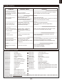
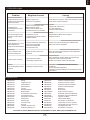
Trouble shooting
Problem Possible Cause Solution
Aircraft will not respond to
the throttlebut responds to
other controls.
-ESC is not armed.
-Throttle channel is reversed.
-Lower throttle stick and throttle trim to lowest settings.
-Reverse throttle channel on transmitter.
Extra propeller noise or
extra vibration.
-Damaged spinner, propeller,
motor or motor mount.
-Loose propeller and spinner parts.
-Propellor installed backwards.
-Replace damaged parts.
-Tighten parts for propeller adapter, propeller and spinner.
-Remove and install propeller correctly.
Reduced flight time or
aircraft underpowered.
-Flight battery charge is low.
-propeller installed backward.
-Flight battery damaged.
-Completely recharge flight battery.
-Replace flight battery and follow flight battery
instructions.
Control surface does not
move, or is slow to respond
to control inputs.
-Control surface, control horn,
linkage or servo damage.
-Wire damaged or connections
loose.
-Replace or repair damaged parts and adjust controls.
-Do a check of connections for loose wiring.
Controls reversed.
Channels are reversed in the
transmitter.
Do the control direction test and adjust controls for
aircraft and transmitter.
-Motor loses power
-Motor power pulses then
motor loses power.
-Damage to motor, or battery.
-Loss of power to aircraft.
-ESC uses default soft Low Voltage
Cutoff(LVC).
-Do a check of batteries, transmitter, receiver, ESC, motor
and wiring for damage(replace as needed).
-Land aircraft immediately and recharge flight battery.
LED on receiver flashes
slowly.
Power loss to receiver.
-Check connection from ESC to receiver.
-Check servos for damage.
-Check linkages for binding.
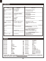
Spare parts list content
FMSRQ101
FMSRQ102
FMSRQ103
FMSRQ104
FMSRQ105
FMSRQ106
FMSRQ107
FMSRQ108
FMSRQ109
FMSRQ110
FMSRQ111
FMSRQ112
FMSRQ113
FMSRQ114
FMSRQ115
FMSRQ116
FMSRQ117
FMSRQ118
Fuselage
Main Wing Set
Vertical stabilizers
Horizontal Stabilizer
Cockpit
Bomb and Missile Set
Twin Engine Compartment
Foam part (Laser racker)
Foam part (fin)
Scale Plastic Parts Set
Control Horns
Linkage Rod
Screw Set
LED
Front Landing Gear Set
Main Landing Gear Set
Front Landing Gear System
Main Landing Gear System
FMSRQ119
FMSRQ120
FMSRQ121
FMSRQ122
FMSCON010
FMSRE027
FMSRE032
FMSDF12B70
PRKV1850
PRESC027
PR13MGAP
PR13MGAR
PR23MGAP
FMSSEQ6S-1
Carbon fiber spars
Front Landing Gear Door
Wheel Set
Decal Sheet
Multi Connector System10
EL-retract
EL Retract
Ducted fan (12-blade)
2860-KV1850 motor
80A ESC X 2 with 8A BEC
Predator 13g analog metal gear servo positive
Predator 13g analog metal gear servo reverse
Predator 23g analog metal gear servo positive
Sequencer-6 sec
Visit our website: www.fmsmodel.com to see photo of this product. Enter the key word "ESC" in the search bar for the
stock ESC instruction manual.

14
WARNUNG: Lesen Sie die GESAMTE Bedienungsanleitung, um sich vor der Inbetriebnahme mit den Funktionen
des Produkts vertraut zu machen.
Wenn das Produkt nicht ordnungsgemäß bedient wird, kann dies zu Schäden am Produkt oder persönlichem
Eigentum führen und schwere Verletzungen verursachen.
Dieses Produkt ist kein Spielzeug! Es muss mit Vorsicht und gesundem Menschenverstand betrieben werden.
Andernfalls kann es zu Verletzungen oder Schäden am Produkt oder anderen Sachwerten führen. Dieses Produkt
ist nicht für den Betrieb durch Kinder ohne direkte Aufsicht von Erwachsenen vorgesehen.
Diese Anleitung enthält Hinweise zu Sicherheit und Wartung. Es ist wichtig, dass vor der Verwendung alle
Anweisungen und Warnungen in der Anleitung gelesen und befolgt werden, um Schäden oder schwere
Verletzungen zu vermeiden.
Warnhinweise
Als Benutzer dieses Produkts sind Sie allein dafür verantwortlich dieses Produkt so zu betreiben, dass weder Sie
selbst noch andere gefährdet oder Schäden am Produkt oder Eigentum anderer verursacht werden.
Dieses Modell wird von einem Funksignal gesteuert, das von vielen Quellen außerhalb Ihrer Kontrolle gestört
werden kann. Solche Störungen können zu einem vorübergehenden Kontrollverlust führen. Daher sollte immer
einen Sicherheitsabstand zu Personen und Gebäuden eingehalten werden.
Altersempfehlung: Nicht für Kinder unter 14 Jahren. Dies ist kein Spielzeug.
· Betreiben Sie Ihr Modell niemals mit leeren Senderbatterien.
· Betreiben Sie Ihr Modell immer in einem offenen Bereich, abseits von Gebäuden, Verkehr oder Personen.
· Befolgen Sie die gesetzlichen Regelungen Ihres Landes zum Betrieb von ferngesteuerten Modellflugzeugen.
· Befolgen Sie sorgfältig die Anweisungen und Warnungen für dieses und alle unterstützenden Geräte, die Sie
verwenden (Ladegeräte, wiederaufladbare Akkus usw.).
· Bewahren Sie alle Chemikalien, Kleinteile und elektrischen Geräte außerhalb der Reichweite von Kindern auf.
· Feuchtigkeit verursacht Schäden an der Elektronik. Vermeiden Sie, dass die Produkte Wasser ausgesetzt
werden, die nicht speziell für diesen Zweck entworfen und geschützt sind.
· Nehmen Sie Teile des Produkts niemals in den Mund, da dies zu schweren Verletzungen oder sogar zum Tod
führen kann.
VORSICHT: Befolgen Sie immer die Anweisungen des Herstellers zur sicheren Verwendung und Entsorgung
von Batterien. Durch falsche Handhabung von Li-Po-Batterien können Feuer, Sachschäden oder schwere
Verletzungen verursacht werden.
Seien Sie sich über alle Risiken klar, die mit dem Umgang von Lithium Polymer (LiPo) Akkus verbunden sind.
Wenn die Akkus zu irgendeinem Zeitpunkt anschwellen oder aufblähen, verwenden Sie diese auf keinen Fall
mehr!
Um die Lebensdauer des Akkus zu verlängern sollten dieser bei Zimmertemperatur in einem trockenen Bereich
gelagert werden. Bewahren Sie den Akku oder das Modell nicht in einem Auto oder in direktem Sonnenlicht
auf. Wenn der Akku über einen längeren Zeitraum zu hohen Temperaturen ausgesetzt wird kann dieser
beschädigt werden oder sogar Feuer fangen.
Verwenden Sie niemals ein NiMh-Ladegerät, um Li-Po-Akkus aufzuladen. Wenn der Akku nicht mit einem
Li-Po-kompatiblen Ladegerät geladen wird, kann dies zu einem Brand führen, der zu Personen- und Sachschäden
führen kann.
Niemals Li-Po Zellen unter 3V entladen.
Lassen Sie Akkus beim Laden niemals unbeaufsichtigt.
Laden Sie niemals beschädigte Akkus auf.
Aufladen des LiPo-Akkus: Verwenden Sie ein Ladegerät, das die Li-Po-Batterie sicher aufladen kann. Lesen
Sie vor dem Gebrauch die Anweisungen des Ladegeräts sorgfältig durch. Achten Sie beim Laden des Akkus
darauf, dass sich der Akku auf einer hitzebeständigen Oberfläche befindet. Es wird auch dringend empfohlen,
den Li-Po Akku in einem feuerbeständigen LiPo-Koffer zu laden. LiPo Koffer finden Sie bei Ihrem Fachhändler
oder im Internet.
Sicherheitsvorkehrungen
Hinweise zu LiPo-Akkus

15
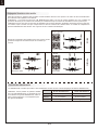
Bitte überprüfen Sie vor der Endmontage ob alle Teile des
Modells enthalten sind. Das folgende Bild zeigt den Inhalt des
Kits.
Sollten Teile fehlen notieren Sie sich bitte den Namen und die
Teilenummer (siehe Ersatzteilliste am Ende dieser
Bauanleitung) und kontaktieren Sie Ihren lokalen Händler oder
senden Sie uns eine E-Mail an [email protected].
Lieferumfang
A: Rumpf
B: Tragfläche
C: Höhenleitwerk
D: Seitenleitwerk
E: Bombenatrappen
F: Kabinenhaube
G: CFK Flächenstäbe
H: Schrauben
I: weiteres Zubehör
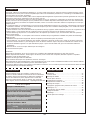
Inhaltsverzeichnis
Einleitung
Spannweite: 1500 mm(59.1in)
Gesamtlänge: 1368 mm(53.9in)
Fluggewicht: ~ 4100 g
Motor: 2860-KV1850
Flächenbelastung: 113.2g/dm²(0.26oz/in²)
Flächeninhalt: 36.2dm²(561sq.in)
Regler: 80A x2
Servo: 5x 13g MG, 4x 23g MG
Empfohlener Akku: 6S (22.2V) 5000mAh 45C
Technische Daten
In 2017 veröffentlichte FMS die A-10 Thunderbolt II. Dank den
herausragenden Scale Details und der brachialen Leistung ist
der “Warthog” bei Piloten uns Zuschauern gleichermaßen
beliebt.
FMS hat nun die erste Generation der A-10 weiterentwickelt um
das Modell mit der V2-Version noch besser zu machen.
Die A-10 V2 bietet tolle neue Eigenschaften, wie eine
verschraubte Konstruktion, Kugelkopfanlenkungen und
verbesserte und festere Flächenholme. Die Scale Details wie
realistische Nieten, abnehmbare Bomben und Raketen und ein
originalgetreues CNC-gefrästes Einziehfahrwerk sind weiterhin
die Highlights des Jet-Modells.
Die A-10 V2 wurde mit 10 wesentlichen Optimierungen
weiterentwickelt und perfektioniert:
1.Bessere Regler: Die dualen 70A-Regler wurden durch zwei
Hobbywing 80A-Regler mit 8A BEC ersetzt.
2.Bessere Servos: Höhen- und Seitenruder werden anstatt mit
den bisherigen 17g-Servos mit 23g-Metallgetriebe-Servos
angelenkt. Dies bedeutet mehr Drehmoment und höhere
Leistung für die Ruderflächen.
3.Optimiertes Fahrwerk: Das Bugfahrwerk wurde komplett neu
entwickelt um das Spiel zu minimieren. Dadurch bleibt das
Modell auch bei hohen Geschwindigkeiten gerade in der Spur.
4.Verbesserte Steckverbindungen: die neuen “Soft”
Steckverbindungen erhöhen Haltbarkeit und Zuverlässigkeit
des Flächenschnellverschluss-Systems (Quick Release System).
5.Optimiertes Höhenleitwerk: Für noch bessere Kontrolle und
Präzision.
6.Optimierte Reifen: eine verbesserte Reifenmischung sorgt für
mehr Langlebigkeit der Fahrwerksräder auch bei rauem
Feldeinsatz.
7.Verbesserter Kabinenverschluss: ein verlängerter Stift zum
Verschluss der Kabinenhaube sorgt für perfekten Halt der
Kabinenhaube während des Fluges.
8.Vergrößertes Akkufach: In der V2 finden zwei 6S 3300mAh
LiPos Platz, wodurch eine deutliche Erhöhung der Flugzeit
erreicht werden kann.
Einleitung
Lieferumfang
Montage des Modells
Einsetzen des Akkus
Anschluss an den Empfänger
Flugvorbereitungen
Montage der Gabelköpfe
Ruderhorn- und Servoarmeinstellung
Schwerpunkt
Vor dem Erstflug
Fluggrundlagen
Problemlösungen
Ersatzteile
···························································15
·······················································
···
15
················································
16
··········································
······20
····································21
·································· ···· ····
···········
·····
21
···············
·················
················
·················
··
··
··
23
23
·······································
23
·············································24
······················································24
····································
········
······
······
········
········
········
········ ········
········25
········································· ········25
9.Neues Farbschema: das Modell verfügt über ein neues,
attraktiveres fertig lackiertes Dekor!
10.Neuer originalgetreuer Pilot
Eigenschaften
• Die 70-mm-Innenläufer mit 12-Blatt-Impeller bieten in
Kombination mit den Hobbywing 80A Reglern enormen Schub.
• Äußerst realistische Scale Details: Nieten, Blechlinien,
stoßdämpfendes Fahrwerk, abnehmbare Bomben und
Raketenhülsen, Pilotfigur usw.
• Ultrahelles LED-Beleuchtungssystem
• Elektronisches CNC-gefrästes Einziehfahrwerk aus Metall
• Große Kugellager im Fahrwerk lassen die A-10 V2 problemlos
über unebenes Gelände rollen
• Vorinstallierte Kugelgelenke und Ruderhörner für präzise
Steuerungen.
Fühle den Unterschied! Bei der Weiterentwicklung der A-10 V2
wurde kein Detail übersehen! Fühle die atemberaubende
Performance des Modells und verdrehe mit Deinem eigenem
“Warthog” jeden Kopf auf dem Flugfeld.
A.
B.
C.
F.
G. H. I.
D.
E.

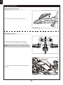
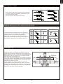
Montage der Kabinenhaube
Montage der Flächen
16
Montage des Modells
1. Setzen Sie die Kabinenhaube wie abgebildet ein.
1. Schieben Sie die Flächenverbinder in den Rumpf.
2. Stecken Sie beide Flächenhälften auf den Verbinder.
Hinweis: Achten Sie darauf, dass das Stecksystem richtig
einrastet.
3. Sichern Sie beide Flächenhälften mit den 4 beiliegenden
Schrauben.
HKM3.0*20

Montage des Höhenleitwerks
17
Montage des Modells
1. Verbinden Sie die Servostecker mit den Kabelverlängerungen
im Höhenruder.
2. Stecken Sie die Höhenruder ein.
3. Sichern Sie die Seitenleitwerke entsprechend der Abbildung
mit 4 Schrauben.
4. Verbinden Sie die Servostecker.
HKM3.0*16

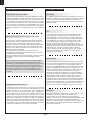
Montage der Scale-Teile
18
Montage des Modells
5. Befestigen Sie das Heckleitwerk mit den entsprechenden
Schrauben am Rumpf.
1. Schieben Sie die Bombenatrappen in die entsprechenden Stellen.
HKM3.0*20
Hinweis: Achten Sie darauf welche Atrappen in welche Stellen passen.

19
Montage des Modells
2. Schrauben Sie die Scale-Teile an die enstprechenden Stellen
in den Flächen.
3. Verkleben Sie die Finnen mit dem Rumpf.
4.Befestigen Sie die weiteren Teile mit Sekundenkleber wie
abgebildet.
Required Adhesives:
Foam Safe Medium CA
Required Adhesives:
Foam Safe Medium CA

1. Nehmen Sie die Haube ab.
2. Befestigen Sie den Akku mit dem Klettband
3. Schieben Sie den geladenen Akku mit den Kabeln nach
hinten in bis ganz nach vorne im Akkufach.
Hinweis: Der Schwerpunkt des Modells kann durch verschieben
des Akkus verändert werden. Der korrekte Schwerpunkt hat
Auswirkungen auf die Flugperformance.
Einsetzen des Akkus
20
Montage des Modells
5. Kleben Sie weitere Scale-Teile fest.
Required Adhesives:
Foam Safe Medium CA
Seite wird geladen ...
Seite wird geladen ...
Seite wird geladen ...
Seite wird geladen ...
Seite wird geladen ...
Seite wird geladen ...
Seite wird geladen ...
Seite wird geladen ...
Seite wird geladen ...
Seite wird geladen ...
Seite wird geladen ...
Seite wird geladen ...
Seite wird geladen ...
Seite wird geladen ...
Seite wird geladen ...
Seite wird geladen ...
Seite wird geladen ...
Seite wird geladen ...
Seite wird geladen ...
Seite wird geladen ...
Seite wird geladen ...
Seite wird geladen ...
Seite wird geladen ...
Seite wird geladen ...
Seite wird geladen ...
Seite wird geladen ...
Seite wird geladen ...
Seite wird geladen ...
Seite wird geladen ...
Seite wird geladen ...
Seite wird geladen ...
Seite wird geladen ...
-
 1
1
-
 2
2
-
 3
3
-
 4
4
-
 5
5
-
 6
6
-
 7
7
-
 8
8
-
 9
9
-
 10
10
-
 11
11
-
 12
12
-
 13
13
-
 14
14
-
 15
15
-
 16
16
-
 17
17
-
 18
18
-
 19
19
-
 20
20
-
 21
21
-
 22
22
-
 23
23
-
 24
24
-
 25
25
-
 26
26
-
 27
27
-
 28
28
-
 29
29
-
 30
30
-
 31
31
-
 32
32
-
 33
33
-
 34
34
-
 35
35
-
 36
36
-
 37
37
-
 38
38
-
 39
39
-
 40
40
-
 41
41
-
 42
42
-
 43
43
-
 44
44
-
 45
45
-
 46
46
-
 47
47
-
 48
48
-
 49
49
-
 50
50
-
 51
51
-
 52
52


FMS FMM113P Bedienungsanleitung
- Kategorie
- Ferngesteuertes Spielzeug
- Typ
- Bedienungsanleitung
- Dieses Handbuch eignet sich auch für
in anderen Sprachen
- English: FMS FMM113P Owner's manual
- français: FMS FMM113P Le manuel du propriétaire
Verwandte Artikel
-
FMS FMM1102PX Bedienungsanleitung
-
FMS 1220mm Super EZ V4 Bedienungsanleitung
-
-
-
FMS FMM131PX Bedienungsanleitung
-
-
-
-
-
Andere Dokumente
-
Modster Piper J3 Bedienungsanleitung
-
E-flite Habu 32 EDF ARF Benutzerhandbuch
-
E-flite EFL011500 Bedienungsanleitung
-
-
 Staufenbiel L-13 Blanik Benutzerhandbuch
-
Arrows HOBBY 1300mm Benutzerhandbuch
-
-
 Winter 7 FMS 4 Installation And Maintenance Instructions
-
Revell F/A-18E Super Hornet Benutzerhandbuch
-
Topcon LS-80A/B/G/L Benutzerhandbuch

