
1
Installation Guide
Danfoss District Energy VI.GP.R1.51 DKDHR
English - GB
If the household plumbing system includes hot water recirculation the water heater must be connected to the hot water recirculation
system by using this circulation set.
It is to be recommended to prepare the water heater for recirculation BEFORE mounting it on the wall.
The recirculation pipe in your household plumbing system must be connected to a nipple, mounted on the circulation pipe of the water
heater. - See pages 2 to 5 for information about preparation of water heater for and connection to the DHW recirculation system.
Remember always to mount circulation pump and non-return valve on the circulation pipe and to mount safety valve on the DCW
inlet. The pump must be installed so that the pump is pumping water towards the water heater.
If a time-controlled pump is used, it is to be recommended that the circulation water temperature is set to approx. 35 °C.
If the circulation pump (outside the water heater) is switched o for a longer period, it is to be recommended that the Danfoss bypass
thermostat is closed during the same period.
NOTE!
Please note that water heaters with Danfoss AVE expanion unit must not be used on systems with DHW recirculation.
Circulation set for water heaters
Cirkulationssæt for vandvarmere
Zirkulationsset für Warmwasserbereiter
Danish - DK
Hvis der er cirkulation på anlægget skal der etableres cirkulationskobling på vandvarmeren ved hjælp af dette cirkulationssæt.
Det anbefales at etablere cirkulation INDEN vandvarmeren hænges op på væggen.
Cirkulationsledningen fra den faste installation tilsluttes på brystniplen nederst i unitten. - Se hvordan man cirkulationskobler vandvar-
meren på side 2 til 5.
Der skal altid monteres pumpe og kontraventil på cirkulationsrøret med owretning ind mod vandvarmeren.
Hvis der anvendes urstyret pumpe, anbefales det, at cirkulationsvandtemperaturen indstilles til ca. 35 °C.
Bemærk, hvis cirkulationspumpen (udenfor unitten) stoppes længerevarende, anbefales det, at by-pass termostaten lukkes i samme tidsrum.
NB!
Vær opmærksom på, at vandvarmere udstyret med Danfoss AVE trykudligner ikke må bruges på anlæg med cirkulation.
German - DE
Wenn eine Zirkulationsleitung in der Hausinstallation vorhanden ist, ist die Warmwasserbereiter an die Zirkulationsleitung anzuschließen,
und eine Umrüstung von Bypassbetrieb auf TWW-Zirkulation ist mittels dieses Zirkulationssatzes vorzunehmen.
Es wird empfohlen die Warmwasserbereiter für TWW-Zirkulation VOR der Montage auf der Wand vorzubereiten.
Die Zirkulationsleitung der Hausinstallation ist an einen Messing-Nippel, den auf dem Zirkulationsschlauch des Warmwasserbereiters
montieret ist, anzuschliessen. - Siehe Seiten 2-5 für weitere Informationen über Zirkulationsanschluss.
Bitte einbau von Umwälzpumpe und Rückschlagventil in der Zirkulationsleitung beachten, und Sicherheitsventil in der Kaltwas-
serzuleitung einzubauen. Die Fleißrichtung der Pumpe ist in Richtung Warmwasserbereiter.
Wird die Umwälzpumpe über eine Schaltuhr gesteuert, empfehlen wir, dass die Zirkulationswassertemperatur auf ungefähr. 35 °C eingestellt
wird.
Wenn die Umwälzpumpe (außerhalb der Warmwasserbereiter) für einen längeren Zeitraum abgeschaltet wird, wird es empfohlen, dass der
Danfoss Bypass Thermostat im gleichen Zeitraum geschlossen wird.
BITTE BEMERKEN!
Der AVE Druckausgleichventil ist nicht auf Systemen mit TWW-Zirkulation zu verwenden.
Div.734 Code No. 004U8442

2
Fig. 1 Fig. 2
Fig. 3 Fig. 4
Fig. 7 Fig. 8
Fig. 5 Fig. 6
DKDHR VI.GP.F1.51 Danfoss District Energy
Installation Guide Akva Lux II & Akva Les II
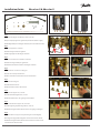
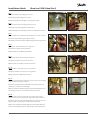
Fig. 1
GB: Demount plugs (6 mm Allen key) from controller.
DK: Fjern nipler/propper fra regulatoren (med 6 mm Unbraco-nøgle).
DE: Die Nippel/Pfropfe vom Regler abbauen (mit 6 mm Inbusschraube).
Fig. 2
GB: Mount nipple A in controller.
DK: Montér nippel-mue A i regulator.
DE: Messingnippel A in den Regler einbauen.
Fig. 3
GB: Mount circulation hose end B1 in controller.
DK: Montér slangeende B1 på regulatoren.
DE: Zirkulationsschlauchende B1 in den Regler einbauen.
Fig. 4
GB: Unscrew the 3 screws on locking rail.
DK: Løsn de 3 skruer på låseskinnen.
DE: Die 3 Schrauben der Verschlussschiene abschrauben
Fig. 5
GB: Demount locking rail.
DK: Afmontér låseskinnen.
DE: Die Verschlussschiene abmontieren
Fig. 6
GB: Demount support rail, as shown.
DK: Afmontér kseringsskinnen, som vist.
DE: Die Festhalteschiene, wie gezeigt, herausnehmen.
Fig. 7
GB: Place bracket C on support rail, as shown.
DK: Anbring beslag C på kseringsskinnen, som vist.
DE: Den Beschlag C auf die Festhalteschiene, wie gezeigt, anbringen.
Fig. 8
GB: Fix bracket C on support rail, by fastening the screws D lightly.
DK: Fastgør beslag C på kseringsskine ved at skrue skruerne let fast.
DE: Den Beschlag C auf die Festhalteschiene montieren, indem Sie die
Schrauben leicht festschrauben.
F
H
A
D
E
B1B2
C
H
G

33
Danfoss District Energy VI.GP.R1.51 DKDHR
Installation Guide Akva Lux II & Akva Les II
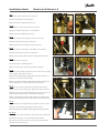
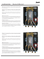
Fig. 9
GB: Demount capillary tube from brass angle piece.
DK: Afmontér kapillarrør fra messingvinklen.
DE: Das Kapillarrohr vom Winkelstück abbauen..
Fig. 10
GB: Mount M8 x 1 screw plug F in the brass angle piece.
DK: Afprop med M8 x 1 konisk prop F i messingvinklen.
DE: M8 x 1Propfen F in Winkelstück einbauen.
Fig. 11
GB: Demount capillary tube from bypass thermostat as shown.
DK: Afmontér kapillarrør fra by-pass termostaten.
DE: Das Kapillarrohrende von Bypass Thermostat abbauen.
Fig. 12
GB: Mount support rail and tighten screws D with your screwdriver.
DK: Montér kseringsskinne og skru skruerne D fast.
DE: Die Festhalteschiene einbauen und die Schrauben D festschrauben.
Fig. 13
GB: Fix locking rail to support rail.
DK: Fastgør låseskinne på kseringsskinne.
DE: Die Verschlussschiene auf die Festhalteschiene befestigen.
Fig. 14
GB: Fit new capillary tube G on nipple A by means of union nut and cutting
ring H. - Tighten with single end wrench.
DK: Montér nyt kapillarrør G på nippelmue A ved hjælp af omløber og
skærering H. - Fastspænd med skruenøgle.
DE: Neues Kapillarrohr G in Messingnippel A mittels Überwurfmutter und
Schneidring H einbauen. - Mit Schraubenschlüssel festspannen.
Fig. 15
UK: Fit the other end of the capillary tube G on bypass thermostat by
means of union nut and cutting ring H. - Tighten with single end wrench.
DK: Montér den anden ende af kapillarrøret G på by-pass termostaten ved
hjælp af omløber og skærering H. - Fastspænd med skruenøgle.
DE: Das andres Kapillarrohrende G in Bypass Thermostat mittels Überwurf-
mutter und Schneidring H einbauen. - Mit Schraubenschlüssel festspannen.
Fig. 16
GB: Fix circulation hose end B2 and hexagon nipple E in bracket, as shown
DK: Monter slangeende B2 og brystnippel E i beslag, som vist.
DE: Zirkulationsschlauchende B2 und Messingnippel E in Beschlag einbauen.
Fig. 17+18
GB: Cut out a section of the insulation to make room for the circulation pipe.
DK: Skær ud i isoleringen, så der er plads til cirkulationsstudsen.
DE: Schneiden Sie einen Teil der Front Isolierung weg, um Platz für den
Zirkulationsanschluss zu machen.
Fig. 13 Fig. 14
Fig. 15 Fig.16
Fig. 17 Fig.18
Fig. 9 Fig. 10
Fig. 11 Fig. 12

4
DKDHR VI.GP.F1.51 Danfoss District Energy
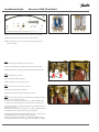
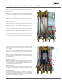
GB: This circulation set applies to the three shown water heater types.
DK: Cirkulationssættet passer til de tre viste vandvarmertyper.
DE: Dieses Zirkulationsset lässt sich in die drei gezeigten Warmwasser-
bereiter einbauen.
Fig. 1
GB: Demount plugs (6 mm Allen key) from controller.
DK: Fjern nipler/propper fra regulatoren (med 6 mm Unbraco-nøgle).
DE: Die Nippel/Pfropfe vom Regler abbauen (mit 6 mm Inbusschraube).
Fig. 2
GB: Mount nipple A in controller.
DK: Montér nippel-mue A i regulator.
DE: Messingnippel A in den Regler einbauen.
Fig. 3
GB: Mount circulation hose end B1 in controller.
DK: Montér slangeende B1 på regulatoren.
DE: Zirkulationsschlauchende B1 in den Regler einbauen.
Fig. 4
GB: Prepare bracket C for mounting on mounting plate by making a 90-degree
bend on one end, using a pair of pliers.
This applies only to Akva Vita II and Akva Les. - For Akva Lux II GW it is not
necessary to bend the bracket before mounting it on the mounting plate.
DK: Forbered beslag C for montage på bagpladen ved at bukke beslaget 90
grader i den ene ende.
Dette gælder kun for Akva Vita II og Akva Les. - For Akva Lux II GW er det ikke
nødvendigt at bukke beslaget før det monteres på bagpladen.
DE: Beschlag C für Montage auf Montageplatte forbereiten, - indem Sie eine
90-Grad-Biegung an einem ende mit einer Zange machen.
Dies gilt nur für Akva Vita II und Akva Les. - Für Akva Lux II GW ist es nicht
notwendig den Beschlag vor der Montage auf der Montageplatte zu biegen.
Installation Guide Akva Lux II GW, Akva Vita II
Fig. 1 Fig. 2
Fig. 3 Fig. 4
F
H
A
D
E
B1
B2
C
H
G
Akva Lux II GW Akva Vita II

55
Danfoss District Energy VI.GP.R1.51 DKDHR
Installation Guide Akva Lux II GW, Akva Vita II
Fig. 5
GB: Place bracket C on mounting plate as shown.
DK: Anbring beslag C på bagpladen, som vist.
DE: Den Beschlag C auf die Rückplatte, wie gezeigt, anbringen.
Fig. 6
GB: Fasten bracket C on mounting plate with screws D.
DK: Fastgør beslag C på bagpladen med skruerne D.
DE: Den Beschlag C auf die Rückplatte mittels Schrauben D festschrauben.
Fig. 7
GB: Fix circulation hose end B2 and hexagon nipple E in bracket as shown.
DK: Montér slangeende B2 og brystnippel E i beslag
DE: Zirkulationsschlauchende B2 und Messingnippel E in Beschlag einbauen.
Fig. 8
GB: Demount capillary tube from brass angle piece.
DK: Afmontér kapillarrør fra messingvinklen.
DE: Das Kapillarrohr vom Winkelstück abbauen.
Fig. 9
GB: Demount capillary tube from bypass thermostat.
DK: Afmontér kapillarrør fra by-pass termostaten.
DE: Das Kapillarrohr vom Bypass Thermostat abbauen.
Fig. 10
GB: Mount M8 x 1 screw plug F in the brass angle piece.
DK: Afprop med M8 x 1 konisk prop F i messingvinklen.
DE: M8 x 1Propfen F in Winkelstück einbauen.
Fig. 11
GB: Fit new capillary tube G on nipple A by means of union nut and cutting
ring H. - Tighten with single end wrench.
DK: Montér nyt kapillarrør G på nippelmue A ved hjælp af omløber og
skærering H. - Fastspænd med skruenøgle.
DE: Neues Kapillarrohr G in Messingnippel A mittels Überwurfmutter und
Schneidring H einbauen. - Mit Schraubenschlüssel festspannen.
Fig. 12
UK: Fit the other end of the capillary tube G on bypass thermostat by
means of union nut and cutting ring H. - Tighten with single end wrench.
DK: Montér den anden ende af kapillarrøret G på by-pass termostaten ved
hjælp af omløber og skærering H. - Fastspænd med skruenøgle.
DE: Das andres Kapillarrohrende G in Bypass Thermostat mittels Überwurf-
mutter und Schneidring H einbauen. - Mit Schraubenschlüssel festspannen.
Fig. 5 Fig. 6
Fig. 7 Fig. 8
Fig. 9 Fig. 10
Fig. 11 Fig.12
Seite wird geladen ...
Seite wird geladen ...

VI.GP.R1.15
Produced by Danfoss Redan A/S © 11/2012
-
 1
1
-
 2
2
-
 3
3
-
 4
4
-
 5
5
-
 6
6
-
 7
7
-
 8
8


Danfoss 004U8243 Installationsanleitung
- Kategorie
- Thermostate
- Typ
- Installationsanleitung
in anderen Sprachen
- English: Danfoss 004U8243 Installation guide
Verwandte Artikel
-
Danfoss 004U8376 Installationsanleitung
-
Danfoss 004U8090 Installationsanleitung
-
-
Danfoss AKVA 20 Installationsanleitung
-
-
-
-
-
