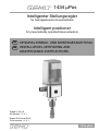
GEM 1434 mPos Installation, Operating And Maintenance Instructions
- Typ
- Installation, Operating And Maintenance Instructions

1434 µPos
1434 μPos
Intelligent positioner
for pneumatically operated linear actuators
Status 01st June 2016
From version 1.1.2.1
GB
INSTALLATION, OPERATING AND
MAINTENANCE INSTRUCTIONS
Intelligenter Stellungsregler
für fremdgesteuerte Linearantriebe
Stand 01.06.16
Ab Version 1.1.2.1
DE
ORIGINAL EINBAU- UND MONTAGEANLEITUNG

2 / 24
1434 µPos
nationalen Vorschriften.
Die Beschreibungen und Instruktionen in
dieser Sicherheitsanweisung beziehen sich
auf die Standardausführung.
Die Sicherheitshinweise berücksichtigen
nicht Zufälligkeiten und Ereignisse,
die bei Montage, Betrieb und Wartung
auftreten können, sowie ortsbezogene
Sicherheitsbestimmungen, für
deren Einhaltung - auch seitens des
hinzugezogenen Montagepersonals - der
Betreiber verantwortlich ist.
Bei Rückfragen wenden Sie sich
bitte an die nächstgelegene GEMÜ-
Verkaufsniederlassung.
1.2 Hinweise zur Sicherheit
Nur qualifiziertes und eingewiesenes
Fachpersonal darf den GEMÜ 1434 μPos
montieren, elektrisch anschließen und
in Betrieb nehmen. Das Personal für
Bedienung, Wartung, Inspektion und
Montage muss die entsprechende
Qualifikation für diese Arbeiten aufweisen.
Verantwortungsbereich, Zuständigkeit und
die Überwachung des Personals muss
durch den Betreiber genau geregelt sein.
Liegen beim Personal nicht die notwendigen
Kenntnisse vor, so ist dieses zu schulen und
zu unterweisen. Dies kann, falls erforderlich,
im Auftrag des Betreibers durch den
Hersteller/Lieferer erfolgen. Weiterhin ist
durch den Betreiber sicherzustellen, dass
der Inhalt der Sicherheitsanweisung durch
das Personal voll verstanden wird. Stellen
Sie unbedingt die elektrische Sicherheit der
speisenden Geräte sicher. Beachten Sie
auch die Einhaltung der elektrischen Daten.
Die Nichtbeachtung der Sicherheitshinweise
kann sowohl eine Gefährdung für Personen
als auch für die Umwelt und den GEMÜ 1434
μPos zur Folge haben. Die Nichtbeachtung
der Sicherheitshinweise kann zum Verlust
jeglicher Schadensersatzansprüche führen.
Gesetzliche Bestimmungen einhalten.
1 Hinweise zu Ihrer Sicherheit
Bitte lesen Sie die nachfolgenden Hinweise
sorgfältig durch und beachten Sie diese.
1.1 Allgemeines
Eine einwandfreie Funktion unseres GEMÜ
1434 μPos setzt folgendes voraus:
• Sachgerechten Transport und Lagerung
• Installation und Inbetriebnahme durch
eingewiesenes Fachpersonal
• Bedienung gemäß dieser Einbau- und
Montageanleitung
• Ordnungsgemäße Instandhaltung
Alle Rechte wie Urheberrechte
oder gewerbliche Schutzrechte
werden ausdrücklich vorbehalten.
Der GEMÜ 1434 μPos ist vom Betreiber
bestimmungsgemäß zu gebrauchen.
Alle Angaben dieser Einbau- und
Montageanleitung in Hinsicht auf
Betrieb, Wartung und Instandhaltung
sind zu beachten und anzuwenden. Bei
Nichtbeachten dieser Angaben erlischt
der Garantieanspruch des Betreibers
sowie die gesetzliche Haftung des
Herstellers.
Der Hersteller übernimmt für den
GEMÜ 1434 μPos keine Verantwortung,
wenn diese Sicherheitshinweise nicht
beachtet werden.
Beachten Sie deshalb:
• Den Inhalt dieser Einbau- und
Montageanleitung
• Die einschlägigen Sicherheitsvorschriften
für die Errichtung und den Betrieb
elektrischer Anlagen
• Dass dieses Gerät nicht im
explosionsgefährdeten Bereich eingesetzt
werden darf.
Die in dieser Einbau- und Montageanleitung
genannten Verordnungen, Normen und
Richtlinien gelten nur für Deutschland.
Bei Einsatz des GEMÜ 1434 μPos in
anderen Ländern sind die dort geltenden
nationalen Regeln zu beachten. Wenn es
sich um harmonisierte europäische Normen,
Standards und Richtlinien handelt, gelten
diese im EG-Binnenmarkt. Für den Betreiber
gelten zusätzlich soweit vorhanden die

3 / 24
1434 µPos
1.3 Bestimmungsgemäßer
Gebrauch
Der GEMÜ 1434 μPos ist für den Einsatz
entsprechend dem Datenblatt in bestimmten
ortsfesten Anlagen geeignet.
Um eine einwandfreie Funktion unserer
Produkte zu erlangen sind die im folgenden
aufgeführten Hinweise zu beachten.
Zusätzlich sind die Angaben auf den
Typenschildern zu beachten.
Wenn diese Hinweise als auch die
Hinweise in der allgemeinen Einbau- und
Montageanleitung nicht beachtet werden
erlischt die Garantie auf den GEMÜ 1434
μPos sowie die gesetzliche Haftung.
Der GEMÜ 1434 μPos dient ausschließlich
als Stellungsregler und ist laut Datenblatt
einzusetzen. Eine andere oder darüber
hinausgehende Benutzung gilt als
nicht bestimmungsgemäß. Für hieraus
resultierende Schäden haftet GEMÜ nicht.
Das Risiko trägt allein der Anwender.
Bitte beachten Sie bei der Planung des
Einsatzes als auch des Betreibens des
Gerätes die einschlägigen allgemein
anerkannten sicherheitstechnischen
Regeln. Für Positionierung und Einbau des
GEMÜ 1434 μPos ist grundsätzlich Planer,
Anlagenbauer bzw. Betreiber verantwortlich.
1.4 Einbaulage
Die Einbaulage des GEMÜ 1434 μPos ist
beliebig.
1.5 Benötigtes Werkzeug für
Einbau und Montage
Benötigtes Werkzeug für Einbau und
Montage ist nicht im Lieferumfang enthalten.
1.6 Wartung und Service
Der GEMÜ 1434 μPos unterliegt bei einem
Einbau und Einsatz gemäß dieser Einbau-
und Montageanleitung und des Datenblattes
keiner Wartung / Service.
Helfen Sie mit das Produkt weiter zu
entwickeln und leiten Sie abweichendes
Verhalten gegenüber der Beschreibung
an Ihren nächstgelegenen GEMÜ-Partner
weiter.
2 Herstellerangaben
2.1 Lieferung
Überprüfen Sie die Ware unverzüglich bei
Erhalt auf Vollständigkeit und Unversehrtheit.
Aus den Versandpapieren geht der
Lieferumfang hervor.
Stellen Sie anhand der Bestellnummern fest,
ob die Ware hinsichtlich der Ausführung und
des Umfangs bestellgemäß geliefert wurde.
Wird der Stellungsregler GEMÜ 1434 μPos
mit einem Ventil als Kompletteinheit bestellt,
so sind diese Teile sowie das dazugehörige
Zubehör bereits komplett montiert und
werkseitig voreingestellt.
Der GEMÜ Stellungsregler ist damit
betriebsbereit (Referenzbedingungen:
Steuerdruck = 6 bar; Betriebsdruck = 0 bar).
2.2 Funktion
Der Stellungsregler GEMÜ 1434 μPos
ist ein intelligenter elektropneumatischer
Stellungsregler zum Anbau an
pneumatische Antriebe. Der GEMÜ 1434
μPos wird standardmäßig direkt an den
Antrieb angebaut. Der entsprechende
Weggeber ist bereits im Stellungsregler
integriert (optional kann GEMÜ 1434 μPos
mit einer M12 Steckverbindung für einen
externen Anbau des Weggebers bestellt
werden). Der Weggeber misst die aktuelle
Position des Ventils und meldet diese an
die Elektronik des GEMÜ 1434 μPos. Diese
vergleicht den Istwert des Ventils mit dem
vorgegebenen Sollwert und regelt bei
entsprechender Regelabweichung das Ventil
nach.

4 / 24
1434 µPos
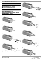
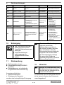
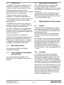
3 Mechanischer Anbau
VORSICHT
Vorgespannte Feder!
ä Beschädigung des Gerätes.
● Feder langsam entspannen.
VORSICHT
Eine Beschädigung der
Spindeloberfl äche kann zum Ausfall
des Weggebers führen!
1.
2.
3.
4.
Spindel festhalten und Betätigungsspindel
handfest anziehen.
5.
6.
7.
8.
9.
10.

5 / 24
1434 µPos
M16 x 1 - SW 24
M12 x 1 - SW 20
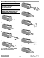
11.
12.
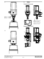
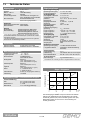
4 Maße
Direkter Anbau [mm]
X1
3
4
X
95
20
13,6
42
55,6
SW 20 bei Anbausatz
M12 x1, x = 9 mm
SW 24 bei Anbausatz
M16 x1, x = 11 mm
Externer Anbau [mm]
20
42
6
11
M20x1,5
SW27
SW24
11
2
21
35
Ø 6,5
158
52
31
7
13,6
95
X1
X3
SW24

6 / 24
1434 µPos
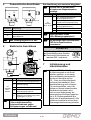
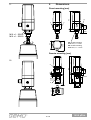
5 Pneumatische Anschlüsse
1
2
M5
3
M6 x 0,75
Anschluss Bezeichnung
1 Versorgungsluftanschluss P (max. 10 bar)
2 Arbeitsanschluss für Prozessventil A1
3
Entlüftungsanschluss R mit integriertem
Rückschlagventil
Max. Versorgungsluft 8/10 bar!
6 Elektrische Anschlüsse
1
5
4
3
2
1
4
3
2
5
X1
X3
X1
X3
X1 X3
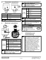
Anschluss Pin Signalname
X1
A-kodiert
M12 -
Stecker
1 U
V
, 24 V DC Versorgungsspannung
2
I+ / U+, 4-20 mA / 0-20 mA / 0-10 V
(Sollwerteingang)
3 I- / U- GND
4
I+ / U+, 4-20 mA / 0-20 mA / 0-10 V
(Istwertausgang-optional)
5
U
V
, Initialisierung 24 V DC,
Auslösung der Initialisierung mittels
Impulssignal t ≥ 100 ms
Bei Anschlussleitungen
>30m installationsseitig
Schutzmaßnahmen gegen
Stoßspannungen vornehmen!
Bei Ausführung mit externem Weggeber:
X3 wird nur in Kombination
mit externem Wegmessystem
benötigt.
Anschluss Pin Signalname
X3
A-kodiert
M12 - Dose
1
UP+, Ausgang Potentiometer
Versorgungsspannung (+)
2
UP, Eingang
Potentiometerschleiferspannung
3
UP-, Ausgang Potentiometer
Versorgungsspannung (-)
4 n. c.
5 n. c.
Reglergehäuse erden
(über Befestigungswinkel)!
Bei Montage des Potentiometers
ESD-Schutzmaßnahmen
vornehmen!
VORSICHT
Kabelbruchgefahr!
ä Beschädigung des Gerätes.
● Elektrische Anschlüsse um
maximal 360° verdrehen.
1
4
3
2
5
max. 360°
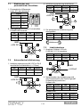
7 Initialisierung und
Inbetriebnahme
Wird der GEMÜ 1434 μPos
ab Werk komplett an ein Ventil
montiert geliefert, so ist dieser
schon werkseitig voreingestellt
(bei einem Steuerdruck von
5,5 - 6 bar ohne Betriebsdruck)
und somit betriebsbereit. Eine
Neuinitialisierung (siehe Kapitel
7.2) wird empfohlen, wenn die
Anlage mit einem abweichenden
Steuerdruck betrieben wird
oder es eine Veränderung der
mechanischen Endlagen gegeben
hat (z. B. Dichtungswechsel am
Ventil oder Antriebsaustausch). Die
Initialisierung bleibt auch bei einer
Spannungsunterbrechung erhalten.

7 / 24
1434 µPos
7.1 Elektrischer und
pneumatischer Anschluss
1. Pneumatische Hilfsenergie
(max. 8/10 bar) aktivieren.
Legende
LED Symbol
Aus
m
An
l
Blinkt schnell
b
Blinkt langsam
I
2. Versorgungsspannung 24 V einschalten.
POWER LED leuchtet.
LED Symbol LED Symbol
OPEN
I
CLOSED
I
ERROR
b
POWER
l
GND
+24V DC
4 3
1 2
5
7.2 Automatische Initialisierung
1. Initialisierungsspannung 24 V DC an Pin 5
anschließen und aktivieren (t > 100ms).
LED Symbol LED Symbol
OPEN
I
CLOSED
I
ERROR
b
POWER
l
GND
+24V DC
4 3
1 2
5
2. Initialisierungsspannung deaktivieren.
LED Symbol LED Symbol
OPEN
I
CLOSED
I
ERROR
m
POWER
l
GND
+24V DC
4 3
1 2
5
3. Die automatische Initialisierung wird
durchgeführt.
LED Symbol LED Symbol
OPEN
I
CLOSED
I
ERROR
m
POWER
l
Initialisierung
7.3 Inbetriebnahme
1. Analogen Sollwert 4-20 mA
(0-20 mA/ 0-10 V) vorgeben.
LED Symbol LED Symbol
OPEN
m
CLOSED
m
ERROR
m
POWER
l
GND
4 3
1 2
5
+4-20mA
2. Nach Beenden der Initialisierung wird
das Prozessventil in die Position gemäß
Sollwertsignal positioniert.
Sollwert min
LED Symbol LED Symbol
OPEN
m
CLOSED
l
ERROR
m
POWER
l
Sollwert max
LED Symbol LED Symbol
OPEN
l
CLOSED
m
ERROR
m
POWER
l

8 / 24
1434 µPos
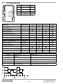
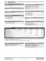
8 Anzeigeelemente
OPEN
ERROR
CLOSED
POWER
Bedeutung Fehlernummer
LED 1
OPEN
LED 2
ERROR
LED 3
CLOSED
LED 4
POWER
Position erreicht -
m m m l
Ventil in Endlage AUF -
l m m l
Ventil in Endlage ZU -
m m l l
Ventil fährt in Richtung AUF -
I m m l
Ventil fährt in Richtung ZU -
m m I l
Regler in Initialisierungsphase -
I m I l
Sollwert > 20,5 mA / 10,25 V Fehler Nr. 1
I b m l
Sollwert < 3,5 mA Fehler Nr. 2
m b I l
Regler nicht initialisiert Fehler Nr. 3
I b I l
Regler nicht kalibriert Fehler Nr. 4
l l l I
Gerätefehler Fehler Nr. 5
m b m l
Regler arbeitet mit geringer Güte Warnung Nr. 1
Z l
Legende LED Zustand Blinkfrequenz
m
LED aus
l
LED an
Z
LED blinkt kurz auf f = 1,66 Hz; 0,15 s an / 0,45 s aus
b
LED blinkt schnell f = 3,33 Hz; 0,15 s an / 0,15 s aus
I
LED blinkt langsam f = 1,66 Hz; 0,30 s an / 0,30 s aus
LED Bezeichnung Farbe
1 OPEN gelb
2 ERROR rot
3 CLOSED orange
4 POWER gelb

9 / 24
1434 µPos
9 Fehlermeldungen
Fehler Fehlermeldung Fehlerursache Auswirkung Fehlerbehebung
Nr. 1
Sollwert > 20,5 mA /
10,25 V
Sollwertsignal > 20,5 mA /
10,25 V
Prozessventil
wird entlüftet
Sollwertsignal überprüfen
Nr. 2 Sollwert < 3,5 mA Sollwertsignal < 3,5 mA
Prozessventil
wird entlüftet
Sollwertsignal überprüfen
Nr. 3 Regler nicht initialisiert Gerät wurde nicht initialisiert Keine Funktion Initialisierung durchführen
Nr. 4 Regler nicht kalibriert Gerät defekt Keine Funktion
Rücksendung zur
Reparatur
Nr. 5 Gerätefehler
a) Fehlende pneumatische
Versorgung
b) Leckage im
pneumatischen System
Initialisierung
fehlerhaft
Prüfen der
a) pneumatischen
Versorgung
b) pneumatischen
Verbindungen
Warnung Fehlermeldung Fehlerursache Auswirkung Fehlerbehebung
Nr. 1
Regler arbeitet mit
geringer Güte
Interne Ventile konnten
während der Initialisierung
nicht optimal vermessen
werden
Keine optimale
Regelung
möglich
Prüfen auf
a) Leckage des
Prozessventils
b) Leichtgängigkeit
des Prozessventils
c) schwankenden
Mediumsdruck während
Initialisierung (falls
möglich Mediumsdruck
absperren)
10 Entsorgung
l Alle Teile entsprechend den
Entsorgungsvorschriften /
Umweltschutzbestimmungen
entsorgen.
l Auf Restanhaftungen
und Ausgasung von
eindiff undierten Medien
achten.
11 Rücksendung
l Stellungsregler reinigen.
l Rücksendeerklärung bei GEMÜ
anfordern.
l Rücksendung nur mit vollständig
ausgefüllter Rücksendeerklärung.
Ansonsten erfolgt keine
7 Gutschrift bzw. keine
7 Erledigung der Reparatur
sondern eine kostenpfl ichtige Entsorgung.
Hinweis zur Rücksendung:
Aufgrund gesetzlicher
Bestimmungen zum Schutz
der Umwelt und des Personals
ist es erforderlich, dass die
Rücksendeerklärung vollständig
ausgefüllt und unterschrieben
den Versandpapieren beiliegt.
Nur wenn diese Erklärung
vollständig ausgefüllt ist, wird die
Rücksendung bearbeitet!
12 Hinweise
Hinweis zur Mitarbeiterschulung:
Zur Mitarbeiterschulung nehmen
Sie bitte über die Adresse auf der
letzten Seite Kontakt auf.
Im Zweifelsfall oder bei Missverständnissen
ist die deutsche Version des Dokuments
ausschlaggebend!

10 / 24
1434 µPos
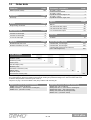
13 Technische Daten
Betriebsbedingungen
Umgebungstemperatur 0 ... +60 °C
Lagertemperatur -10 ... +60 °C
Steuermedium Qualitätsklassen
nach DIN ISO 8573-1
Staubgehalt Klasse 3
(max. Teilchengröße 5 µm)
(max. Teilchendichte 5 mg/m³)
Drucktaupunkt Klasse 3
(max. Drucktaupunkt -20 °C)
Ölgehalt Klasse 3
(max. Ölkonzentration 1 mg/m³)
Zuluft 1...10 bar bei 40 °C
1...8 bar bei 60 °C
Luftverbrauch 0 l/min
(im ausgeregelten Zustand)
Luftleistung 15 Nl/min
Werkstoffe
Gehäuseoberteil Polypropylen (UV-stabil)
Gehäuseunterteil Aluminium eloxiert o. Edelstahl
Elektrische Daten
Spannungsversorgung
Spannungsversorgung U
V
= 18...30 V DC
Leistungsaufnahme ≤ 4 W (bis 24 V DC)
Analogeingänge
Genauigkeit / Linearität ≤ ± 0,3 % v.E.
Temperatur Drift ≤ ± 0,3 % v.E.
Sollwerte a) 0 - 10 V; b) 0/4...20 mA
Eingangsart passiv
Eingangswiderstand a) 100 kΩ; b) 50 Ω
Auflösung 12 bit
Externer Weggeber RG = 1-10 kΩ
Digitaleingang
Initialisierungseingang
Spannung U
Nenn
= 24 V DC
Pegel ”Logisch 1” 14 V DC ≤ U
H
≤ 30 V DC
Pegel ”Logisch 0” 0 V DC ≤ U
L
≤ 8 V DC
Eingangsstrom I
typ
= 1,3 mA (bei 24 V DC)
Analogausgang (optional)
Genauigkeit / Linearität ≤ ± 1,0 % v.E..
Temperatur Drift ≤ ± 0,5 % v.E.
Auflösung 12 bit
Istwertausgang 0 - 20 mA / 4 - 20 mA
Bürde max. 600 Ω, 0-10 V
Ausgangsart aktiv
Elektrischer Anschluss
Spannungsversorgung 1 x M12 Stecker A-kodiert
u. Signalanschlüsse (Installation - Betriebsanleitung
beachten)
Reglerangaben*
Regelabweichung ≤ 1%
Initialisierung automatisch über 24 V DC Signal
Dichtschließfunktion ZU: W ≤ 0,5%; AUF: W ≥ 99,5%
Anzeigeelemente
Status Anzeige 4 gut sichtbare LED`s
* Störeinflüsse auf Sollwertsignal können Regelaktivitäten beeinflussen
Wegmess-System - bei direktem Anbau integriert
Linear-Ausführung
Hub 0.8...10 mm (Code 010)
2.0...25 mm (Code 030)
Widerstand R 1 / 3 kΩ
Mindesthub ≥ 8 % der Weggeberlänge
Allgemeines
Schutzart nach EN 60529 IP 65 / IP 67 ¹⁾
Gewicht 220 g
Maße L x B x H siehe Bemaßung
Einbaulage beliebig
Verwendungszweck zum Anbau an und regeln von
pneu. betätigten Prozessventilen
Besonderheiten Sicherheitsfunktion bei
Stromversorgungsausfall
²⁾
Richtlinien
Niederspannungsrichtlinie 2006/95/EG
EMV-Richtlinie 2004/108/EG
Normen
Störfestigkeit DIN EN 61000-6-2 (März 2006)
Störaussendung DIN EN 61000-6-4 (Sep. 2011)
Störaussendungsklasse: Klasse A
Störaussendungsgruppe: Gruppe 1
¹⁾
IP 67 wird bei geführter Abluft erreicht. Hierzu bei Anschluss 3 und
4
Verschlussschrauben durch M5-Adapter (1434 000 Z2, 2 Stück
erforderlich) ersetzen.
²⁾ bei einem Ausfall der Stromversorgung wird beim zu regelnden
Prozessventil die Zuluftleitung entlüftet.
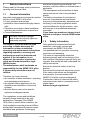
Der Stellungsregler GEMÜ 1434 μPos erkennt automatisch
während der Initialisierung die Steuerfunktion des Ventils:
Federkraft geöffnet (NO) oder Federkraft geschlossen (NC)
Bei Signalvorgabe 0/4 mA oder 0 V ist die Stellung des
Ventils geschlossen.
Regel - Diagramm
Ventilöffnungsgrad [%]
0
4
0
mA
mA
V
20
20
10
15
16
7,5
10
12
5
5
8
2,5
0
75
100
50
25

11 / 24
1434 µPos
14 Bestelldaten
Hinweis: Anbausatz 1434 S01 Z.../4232 S01 Z... ventilbezogen. Bitte separat bestellen mit Angabe des Ventiltyps, DN und
Steuerfunktion. Weggeberlänge vom Anbausatz beachten. Ein Fitting und Pneumatikschlauch für das Ventill, liegt jedem Regler
mit Anschluss Pneumatisch (Code 2 und 3) bei.
Die Abbildung auf Seite 1 zeigt den Stellungsregler GEMÜ 1434 μPos mit Anbausatz.
Bestellbeispiel
1434 000 Z 1 A 14 3 00 01 010
Typ 1434
Feldbus (Code) 000
Zubehör (Code) Z
Wirkungsweise (Code) 1
Sollwerteingang (Code) A
Werkstoff (Code) 14
Anschluss Pneumatisch (Code) 3
Option (Code) 00
Durchflussleistung (Code) 01
Weggeberausführung (Code) 010
Feldbus Code
Ohne (3-Leiter Ausführung) 000
Zubehör Code
Zubehör Z
Wirkungsweise Code
Einfachwirkend, druckentlüftend 1
Sollwerteingang Code
4-20 mA Sollwerteingang A
0-20 mA Sollwerteingang B
0-10 V Sollwerteingang C
Werkstoff Code
Unterteil Aluminium, Oberteil PP 14
Unterteil Edelstahl, Oberteil PP 07
Benötigte Teile für direkten Anbau
GEMÜ 1434...010/030 (Stellungsregler)
GEMÜ 1434 S01 Z... (Anbausatz für Weggeber)
GEMÜ 1219... (Anschluss-Dose)
Benötigte Teile für externen Anbau
GEMÜ 1434...S01 (Stellungsregler)
GEMÜ 4232 S01 Z... (Anbausatz für Weggeber)
GEMÜ 4232 000 Z... 4001 (Weggeber)
GEMÜ 1434 000 Z MP (Befestigungswinkel)
GEMÜ 1219... (Anschluss-Dose)
Anschluss Pneumatisch Code
Zuluft / Ausgang über M5 Anschlussgewinde 1
Zuluft / Ausgang über Schnellsteckverbinder
winklig, 4 mm 2
Zuluft / Ausgang über Schnellsteckverbinder
winklig, 6 mm 3
Option Code
Ohne 00
4-20 mA Istwertausgang A0
0-20 mA Istwertausgang B0
0-10 V Istwertausgang C0
Durchflussleistung Code
15 Nl/min 01
Weggeberausführung Code
Potentiometer, 10 mm Länge 010
Potentiometer, 30 mm Länge 030
Potentiometer extern, Steckverbinder M12,
(max. Leitungslänge 30 m) S01

12 / 24
1434 µPos
1 Safety instructions
Please read the following safety instructions
carefully and observe them!
1.1 General information
Important requirements to ensure the perfect
function of this GEMÜ 1434 μPos:
• Proper transport and storage
• Installation and commissioning by trained
staff
• Operation according to these installation,
operating and maintenance instructions
• Correct maintenance
All rights including copyright
and industrial property rights are
expressly reserved.
The GEMÜ 1434 μPos must be used
according to these directions. All
information in these installation,
operating and maintenance instructions
regarding operation, servicing and
maintenance must be observed and
applied. If the information is not
observed, the operator‘s guarantee
rights and the manufacturer‘s legal
liability cease.
The manufacturer shall undertake no
responsibility for the GEMÜ 1434 μPos
if these safety instructions are not
fulfilled.
Therefore, you must observe:
• the contents of these installation, operating
and maintenance instructions
• the relevant safety regulations for the
installation and operation of electrical
systems
• that this device must not be used in
explosion-endangered areas.
The regulations, norms and guidelines
named in these instructions are only
applicable in Germany. If the GEMÜ
1434 μPos is used in other countries, the
local regulations must be observed. When
dealing with harmonised European norms,
standards and guidelines, these apply
within the Single European Market, the
operator must also adhere to national rules if
applicable.
The descriptions and instructions in these
safety instructions refer to the standard
design.
The safety instructions do not take into
account, coincidences and events that
may occur during assembly, operation and
servicing. Local safety regulations which
must be adhered to by the operator - also
with respect to any additional assembly
personnel.
If you have any questions, please do not
hesitate to ask your closest GEMÜ sales
office.
1.2 Safety information
Only qualified and trained staff should
assemble, electrically connect and
commission the GEMÜ 1434 μPos.
Use qualified staff for operation, servicing,
inspection and assembly.
The areas of responsibility should be
defined precisely and the monitoring of the
staff and their competence carried out by the
operator. Ensure that all staff understand the
safety instructions.
Ensure the electrical safety of the host
devices.
Ensure that the electrical values are correct.
If the safety instructions are disregarded
then persons, the environment and
GEMÜ 1434 μPos may be endangered.
Furthermore, failure to observe the safety
instructions may lead to a complete loss of
claims rights.
Adhere to legal regulations!

13 / 24
1434 µPos
1.3 Correct use
The GEMÜ 1434 μPos is suitable for use in
fixed plant according to the data sheet.
In order to obtain correct product function,
the following instructions should be
observed and the information on the product
labels must also be complied with.
If these instructions and the general
installation, operating and maintenance
instructions are not observed, the guarantee
for the GEMÜ 1434 μPos and the legal
liability expires.
The GEMÜ 1434 μPos serves solely as a
positioner and process controller and must
be used according to the data sheet.
Any other or additional use is regarded as
contrary to regulations and GEMÜ shall not
be liable for any consequential damage. The
user carries sole risk.
Please pay attention to the pertinent
technical safety regulations when planning
both the use and operation of the device.
The designer, plant constructor or operator
is always responsible for positioning and
installation of the GEMÜ 1434 μPos.
1.4 Mounting position
The mounting position of the GEMÜ
1434 μPos is optional.
1.5 Tools needed for installation
and assembly
The tools needed for installation and
assembly are not included in the scope of
delivery.
1.6 Maintenance and service
If the GEMÜ 1434 μPos is installed and
used according to these installation,
operating and maintenance instructions and
the data sheet, no maintenance / service is
necessary.
To assist us in further development of this
product please forward information about
behaviour that varies from the instructions to
your nearest GEMÜ partner.
2 Manufacturer’s Information
2.1 Supply
Check whether the equipment is complete
and undamaged immediately after receipt.
The items in the delivery are detailed in the
shipping documents.
Use the order numbers to check whether
the type and scope has been delivered as
ordered.
If the GEMÜ 1434 μPos positioner is ordered
as a complete unit with a valve, these parts
and the accessories belonging to them are
supplied ready assembled and factory set.
The GEMÜ positioner is then ready for
immediate operation (reference conditions:
control pressure = 6 bar; operating pressure
= 0 bar).
2.2 Function
The GEMÜ 1434 μPos is an intelligent
electropneumatic positioner that can be
attached to pneumatic actuators. Normally
the GEMÜ 1434 μPos is attached directly
to the actuator. The travel sensor is already
integrated in the positioner (the GEMÜ 1434
μPos can be optionally ordered with an M12
cable plug for the external attachment of the
travel sensor). The travel sensor measures
the current valve position and registers it to
GEMÜ 1434 μPos electronics. It compares
the actual valve value with the preset set
value and readjusts it if it varies too much
from the standard tolerance.

14 / 24
1434 µPos
3 Mechanical mounting
CAUTION
Pretensioned spring!
ä Damage to the device.
● Slowly relax spring.
CAUTION
Damage to the spindle surface may
lead to failure of the travel sensor!
1.
2.
3.
4.
Fix the spindle and screw the operating
bush strongly onto the spindle.
5.
6.
7.
8.
9.
10.

15 / 24
1434 µPos
M16 x 1 - SW 24
M12 x 1 - SW 20
11.
12.
4 Dimensions
Direct mounting [mm]
X1
3
4
X
95
20
13,6
42
55,6
SW 20 with mounting
kit M12 x1, x = 9 mm
SW 24 with mounting
kit M16 x1, x = 11 mm
Remote mounting [mm]
20
42
6
11
M20x1,5
SW27
SW24
11
2
21
35
Ø 6,5
158
52
31
7
13,6
95
X1
X3
SW24

16 / 24
1434 µPos
5 Pneumatic connections
1
2
M5
3
M6 x 0,75
Connection Description
1 Air supply connection P (max. 10 bar)
2 Working connection process valve A1
3
Venting connection R with integrated
check valve
Max. air supply 8/10 bar!
6 Electrical connections
1
5
4
3
2
1
4
3
2
5
X1
X3
X1
X3
X1 X3
Connection Pin Signal name
X1
A coded
M12 plug
1 U
V
, 24 V DC supply voltage
2
I+ / U+, 4-20 mA / 0-20 mA / 0-10 V
(set value input)
3 I- / U- GND
4
I+ / U+, 4-20 mA / 0-20 mA / 0-10 V
(actual value output-optional)
5
U
V
, initialisation 24 V DC,
initialisation is started by an impulse
signal t ≥ 100 ms
For connection cables >30m
install precautionary measures
against surge voltage!
For version with external travel sensor:
X3 is only required in
combination with an external
travel sensor system.
Connection Pin Signal name
X3
A-coded
M12 socket
1
UP+, output potentiometer supply
voltage (+)
2
UP, input potentiometer wiper
voltage
3
UP-, output potentiometer supply
voltage (-)
4 n. c.
5 n. c.
Earth the positioner housing
(via mounting bracket)!
Take ESD precautionary
measures when mounting the
potentiometer!
CAUTION
Danger of cable break!
ä Damage to the device.
● Turn electrical connections
max. 360°.
1
4
3
2
5
max. 360°
7 Initialisation and
commissioning
If the GEMÜ 1434 μPos is delivered
fully mounted to a valve ex works,
it is already preset at the factory
(at a control pressure of 5.5 - 6 bar
without operating pressure) and
is therefore ready for operation. A
reinitialisation (see chapter 7.2)
is recommended if the plant is
operated with a diff erent control
pressure or if the mechanical end
positions have been changed (e.g.
seal replacement on the valve
or actuator replacement). The
initialisation is retained even in the
event of voltage cutoff .

17 / 24
1434 µPos
7.1 Electrical and pneumatic
connection
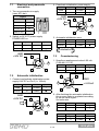
1. Turn on pneumatic air supply
(max. 8/10 bar).
Legend
LED Symbol
OFF
m
ON
l
Flashes fast
b
Flashes slow
I
2. Switch on 24 V DC power supply.
POWER LED on.
LED Symbol LED Symbol
OPEN
I
CLOSED
I
ERROR
b
POWER
l
GND
+24V DC
4 3
1 2
5
7.2 Automatic initialisation
1. Connect and activate initialisation power
supply 24 V DC on Pin 5 (t > 100ms).
LED Symbol LED Symbol
OPEN
I
CLOSED
I
ERROR
b
POWER
l
GND
+24V DC
4 3
1 2
5
2. Deactivate initialisation power supply.
LED Symbol LED Symbol
OPEN
I
CLOSED
I
ERROR
m
POWER
l
GND
+24V DC
4 3
1 2
5
3. Automatic initialisation runs.
LED Symbol LED Symbol
OPEN
I
CLOSED
I
ERROR
m
POWER
l
Initialisation
7.3 Commissioning
1. Specify an analogue set value 4-20 mA
(0-20 mA/ 0-10 V).
LED Symbol LED Symbol
OPEN
m
CLOSED
m
ERROR
m
POWER
l
GND
4 3
1 2
5
+4-20mA
2. After finishing the automatic initialisation
the process valve is regulated according
to the set value signal.
Set value min
LED Symbol LED Symbol
OPEN
m
CLOSED
l
ERROR
m
POWER
l
Set value max
LED Symbol LED Symbol
OPEN
l
CLOSED
m
ERROR
m
POWER
l

18 / 24
1434 µPos
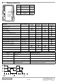
8 Display elements
OPEN
ERROR
CLOSED
POWER
Meaning Error number
LED 1
OPEN
LED 2
ERROR
LED 3
CLOSED
LED 4
POWER
Position reached -
m m m l
Valve OPEN -
l m m l
Valve CLOSED -
m m l l
Valve moved OPEN direction -
I m m l
Valve moved CLOSED direction -
m m I l
Positioner in initialisation mode -
I m I l
Set value signal > 20.5 mA / 10.25 V Error No. 1
I b m l
Set value signal < 3.5 mA Error No. 2
m b I l
Positioner is not initialized Error No. 3
I b I l
Positioner is not calibrated Error No. 4
l l l I
Device error Error No. 5
m b m l
Positioner works with lower quality Warning No. 1
Z l
Legend LED condition Flashing frequency
m
LED off
l
LED on
Z
LED flashes briefly f = 1.66 Hz; 0.15 s on / 0.45 s off
b
LED flashes fast f = 3.33 Hz; 0.15 s on / 0.15 s off
I
LED flashes slowly f = 1.66 Hz; 0.30 s on / 0.30 s off
LED Description Colour
1 OPEN yellow
2 ERROR red
3 CLOSED orange
4 POWER yellow

19 / 24
1434 µPos
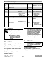
9 Error messages
Error Error message Error cause Error effect Error clearance
No. 1
Set value signal
> 20.5 mA / 10,25 V
Set value signal
> 20.5 mA / 10.25 V
Process valve
vented
Check the set value signal
No. 2
Set value signal
< 3.5 mA
Set value signal < 3.5 mA
Process valve
vented
Check the set value signal
No. 3 Positioner is not initialized Positioner is not initialized No function Start the initialisation
No. 4
Positioner is not
calibrated
Device defect No function Send to GEMÜ for repair
No. 5 Device error
a) Missing pneumatic
air supply
b) Leakage in
pneumatic system
Initialisation
failure
a) Check pneumatic
air supply
b) Check pneumatic
connections
Warning Error message Error cause Error effect Error clearance
No. 1
Positioner works but at
lower accuracy
During initialisation, the
internal valves could not
be measured exactly
Control is not
optimized
Check for
a) Leakage of process
valve
b) Correct function of
process valve
c) Unstable medium
pressure during
initialisation (if possible
turn off medium
pressure)
10 Disposal
l All parts must be disposed
of according to relevant
local or national disposal
regulations / environmental
protection laws.
l Pay attention to adhered
residual material and gas
diff usion from penetrated
media.
11 Returns
l Clean the positioner.
l Request a goods return declaration form
from GEMÜ.
l Returns must be made with a completed
declaration of return.
If not completed, GEMÜ cannot process
7 credits or
7 repair work
but will dispose of the goods at the
operator’s expense.
Note for returns:
Legal regulations for the protection
of the environment and personnel
require that the completed and
signed goods return declaration
is included with the dispatch
documents. Returned goods can
be processed only when this
declaration is completed.
12 Information
Note on staff training:
Please contact us at the address
on the last page for staff training
information.
Should there be any doubts or
misunderstandings in the preceding text,
the German version of this document is the
authoritative document!

20 / 24
1434 µPos
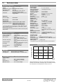
13 Technical data
0
4
0
mA
mA
V
20
20
10
15
16
7,5
10
12
5
5
8
2,5
0
75
100
50
25
During initialisation the 1434 μPos automatically detects the
actuator control function (Normally Open or Normally Closed).
For all valves the Closed position is at 0/4 mA or 0 V.
Regulation diagram
Valve opening degree [%]
Electrical data
Power supply
Power supply
U
V
= 18...30 V DC
Power consumption ≤ 4 W (up to 24 V DC)
Analogue inputs
Accuracy / Linearity ≤ ± 0,3 % F.S.
Temperature drift ≤ ± 0.3 % F.S.
Set value a) 0-10 V; b) 0/4...20 mA
Input passive
Input resistance a) 100 kΩ; b) 50 Ω
Resolution 12 bit
External travel sensor
R
G
= 1-10 kΩ
Digital input
Initialisation input
Voltage
U
rated
= 24V DC
Level "Logical 1" 14 V DC ≤ U
H
≤ 30 V DC
Level "Logical 0" 0 V DC ≤ U
L
≤ 8 V DC
Input current
I
typ
= 1.3 mA (at 24V DC)
Analogue output (optional)
Accuracy / Linearity ≤ ± 1.0 % F.S.
Temperature drift ≤ ± 0.5 % F.S.
Resolution 12 bit
Actual value output 0 - 20 mA / 4 - 20 mA
load resistor max. 600 Ω, 0-10 V
Output active
Electrical connection
Power supply 1 x M12 plug (A-coded)
and signal connections (Installation: Observe operating
instructions)
Positioner data
System deviation ≤ 1%
Initialisation Automatic via 24 V DC signal
Close tight function CLOSED: W ≤ 0.5%; OPEN: W ≥ 99.5%
Display elements
Status display 4 visible LEDs
* Interferences on set value signal may influence control activities
Operating conditions
Ambient temperature 0 to +60 °C
Storage temperature -10 to +60 °C
Control medium Quality classes to DIN ISO 8573-1
Dust content Class 3
(max. particle size 5 µm)
(max. particle density 5 mg/m³)
Pressure dew point Class 3
(max. pressure dew point -20 °C)
Oil concentration Class 3
(max. oil concentration 1 mg/m³)
Air supply 1 to 10 bar at 40 °C
1 to 8 bar at 60 °C
Air consumption 0 l/min (when idle)
Air output 15 Nl/min
Materials
Housing cover Polypropylene (UV-stabilized)
Housing base Anodized aluminium or stainless steel
Travel sensor system -
integrated for direct mounting
Linear version
Stroke 0.8 to 10 mm (code 010)
2.0 to 25 mm (code 030)
Resistance R 1 / 3 kΩ
Minimum stroke ≥ 8% of travel length
General information
Protection class to EN 60529 IP 65 / IP 67 ¹⁾
Weight 220 g
Dimensions L x W x H See dimensional drawing
Mounting position Optional
Intended use For mounting to and control of
pneumatic process valves
Particulars Fail safe function in case of power
supply failure ²⁾
Directives
EC low voltage 2006/95/EG
EMV directive 2004/108/EG
Conformities
Interference resistance
DIN EN 61000-6-2 (March 2006)
Interference emission DIN EN 61000-6-4 (Sep. 2011)
Interference emission class A
Interference emission group 1
¹⁾
IP 67 rating applies when using piped air outlets. Replace
threaded
plug connectors 3 and 4 by M5 adapters (1434 000 Z2, 2 pieces
required) for this purpose.
²⁾
the air supply line of the process valve is vented in case of power
supply failure.
Seite wird geladen ...
Seite wird geladen ...
Seite wird geladen ...
Seite wird geladen ...
-
 1
1
-
 2
2
-
 3
3
-
 4
4
-
 5
5
-
 6
6
-
 7
7
-
 8
8
-
 9
9
-
 10
10
-
 11
11
-
 12
12
-
 13
13
-
 14
14
-
 15
15
-
 16
16
-
 17
17
-
 18
18
-
 19
19
-
 20
20
-
 21
21
-
 22
22
-
 23
23
-
 24
24


GEM 1434 mPos Installation, Operating And Maintenance Instructions
- Typ
- Installation, Operating And Maintenance Instructions
in anderen Sprachen
- English: GEM 1434 mPos
Verwandte Artikel
-
GEM 1434 mPos Installation, Operating And Maintenance Instructions
-
-
-
-
-
Andere Dokumente
-
Gemu 1435 ePos Bedienungsanleitung
-
Gemu 1235 Bedienungsanleitung
-
-
-
-
-
 Ditel KOS527 Technical Manual
-
Gemu ADA 2500U Bedienungsanleitung
-
Makita 4013D Benutzerhandbuch
-
sauter EQJW 246 Benutzerhandbuch
