
www.dell.com | support.dell.com
Dell™ PowerEdge™
SC1420 Systems
Information Update
信息更新
Mise à jour des informations
Aktuelle Informationen
アップデート情報
정보 업데이트
Actualización de información


www.dell.com | support.dell.com
Dell™ PowerEdge™
SC1420 Systems
Information Update

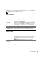
Notes, Notices, and Cautions
NOTE: A NOTE indicates important information that helps you make better use of your computer.
NOTICE: A NOTICE indicates either potential damage to hardware or loss of data and tells you how
to avoid the problem.
CAUTION: A CAUTION indicates a potential for property damage, personal injury, or death.
Abbreviations and Acronyms
For a complete list of abbreviations and acronyms, see "Glossary" in your
User’s Guide
.
____________________
Information in this document is subject to change without notice.
© 2004 Dell Inc. All rights reserved.
Reproduction in any manner whatsoever without the written permission of Dell Inc. is strictly forbidden.
Trademarks used in this text: Dell, the DELL logo, and PowerEdge are trademarks of Dell Inc.; Microsoft and Windows are registered trademarks
of Microsoft Corporation; Red Hat is a registered trademark of Red Hat, Inc.
Other trademarks and trade names may be used in this document to refer to either the entities claiming the marks and names or their products.
Dell Inc. disclaims any proprietary interest in trademarks and trade names other than its own.
October 2004 P/N J4706 Rev. A05

Contents 3
Contents
Installing Microsoft Windows Small Business Server 2003 . . . . . . . . . 5
Installing Red Hat Enterprise Linux ES (version 3)
. . . . . . . . . . . . . . 5
Memory Cooling Fan and Shroud
. . . . . . . . . . . . . . . . . . . . . . 5
Installing the Memory Cooling Fan and Shroud
. . . . . . . . . . . . . 6
System Error Messages
. . . . . . . . . . . . . . . . . . . . . . . . . . 7
System Setup Options
. . . . . . . . . . . . . . . . . . . . . . . . . . . 8
Main Screen
. . . . . . . . . . . . . . . . . . . . . . . . . . . . . 8
Assigning a System Password
. . . . . . . . . . . . . . . . . . . . . . . 14
Using Your System Password to Secure Your System
. . . . . . . . . . 15
Operating With an Admin Password Set
. . . . . . . . . . . . . . . . . . 15
Systems With Four Hard Drives or a Tape Backup Unit
. . . . . . . . . . . . 16
Installing SCSI Hard Drives
. . . . . . . . . . . . . . . . . . . . . . . . 16
Missing Memory in Systems With PCI Express ("Memory Hole")
. . . . . . . 17

4 Contents
Figures
Figure 1-1. Installing the Memory Cooling Fan and Shroud . . . 6
Figure 1-2. Main System Setup Program Screen
. . . . . . . . 8
Figure 1-3. Installing SCSI Hard Drives
. . . . . . . . . . . . 16
Tables
Table 1-1. System Messages . . . . . . . . . . . . . . . . . 7
Table 1-2. System Options
. . . . . . . . . . . . . . . . . . 9
Table 1-3. Drive Options
. . . . . . . . . . . . . . . . . . . 9
Table 1-4. Onboard Devices Options
. . . . . . . . . . . . 10
Table 1-5. Performance Options
. . . . . . . . . . . . . . 11
Table 1-6. Security Options
. . . . . . . . . . . . . . . . 11
Table 1-7. Power Management Options
. . . . . . . . . . . 12
Table 1-8. Maintenance Options
. . . . . . . . . . . . . . 13
Table 1-9. POST Behavior Options
. . . . . . . . . . . . . 13

Information Update 5
This document provides updated information for your system on the following topics:
• Installing Microsoft
®
Windows
®
Small Business Server 2003
• Installing Red Hat
®
Enterprise Linux ES (version 3)
• Memory cooling fan and shroud
• System error messages
• System setup options
• Execute Disable feature (System Setup options/Security options)
• Assigning a system password
• Operating with an admin password set
• Systems with four hard drives or a tape backup unit
• Installing SCSI hard drives
• Missing Memory in Systems With PCI Express ("Memory Hole")
Installing Microsoft Windows Small Business Server 2003
If you install Microsoft Windows Small Business Server 2003 on a Dell™ PowerEdge™
SC
1420, the
installation process may appear to cease with about thirteen minutes remaining during the time
when Windows reports that it is registering components. During this portion of the installation,
Windows installs additional security updates and patches, which may take significantly longer to
install than the reported expected time remaining. While these updates are installing, you should
take no action and allow the installation the necessary time to complete. Dell testing has shown the
delay to range from 5 to over 45 minutes, depending upon your hardware configuration. Microsoft
has documented this behavior in Knowledge Base article #839492.
Installing Red Hat Enterprise Linux ES (version 3)
Before installing Linux on your system, change the
SATA Operation
option under the
Drives
menu
in the System Setup program to
RAID Off
.
Memory Cooling Fan and Shroud
NOTICE: If you install more than 4 GB of memory, you must install the memory cooling fan and shroud
to prevent the memory from overheating. If you do not install the memory cooling fan and shroud, you will
receive an error message stating that you must install a fan or remove some memory.

6 Information Update
www.dell.com | support.dell.com
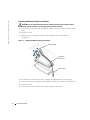
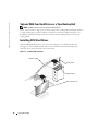
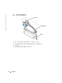
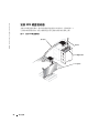
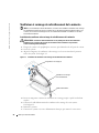
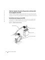
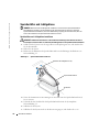
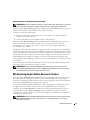
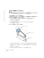
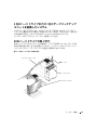
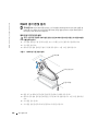
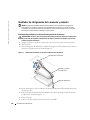
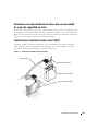
Installing the Memory Cooling Fan and Shroud
CAUTION: See your System Information Guide for complete information about safety precautions,
working inside the computer, and protecting against electrostatic discharge.
1
Turn off the system and attached peripherals, and disconnect the system from the electrical
outlet.
2
Open the system.
3
Align the memory cooling fan and shroud tabs with the holes on the back panel.
See Figure 1-1.
Figure 1-1. Installing the Memory Cooling Fan and Shroud
4
Insert the tabs and lower the memory cooling fan and shroud until it snaps into place.
5
Connect the memory cooling fan and shroud power cable to the system board. See Figure 1-1.
6
Close the system.
7
Reconnect the system to the electrical outlet, and turn on the system.
cooling fan
and shroud
shroud tabs (4)
power cable

Information Update 7
System Error Messages
Table 1-1 lists the system error messages that have been added to POST.
Table 1-1. System Messages
Message Causes Corrective Actions
Alert! Memory fan has
failed or is not present.
A memory fan is required
for the current memory
configuration. Please see
the documentation that
came with your computer
for more information.
Greater than 4 GB memory installed
without installing required memory
fan.
Install or replace the memory cooling fan
and shroud.
Alert! Operating in debug
mode. Please populate
memory in pairs for normal
operation.
Only one memory module with a
capacity greater than 256 MB is
installed in DIMM_1.
You will see this error message when
troubleshooting memory modules. After
you have completed the troubleshooting
procedures, populate the memory in
identical pairs. See "Troubleshooting
System Memory" and "Memory
Installation Guidelines" in your
Installation and Troubleshooting Guide.
Alert! Unable to
initialize fan controller.
Faulty system board. See "Getting Help" in your Installation
and Troubleshooting Guide.
Error! Memory configured
incorrectly. Please enter
Setup for Memory Info
details.
The memory modules are installed
incorrectly.
See "Memory Installation Guidelines"
in your Installation and Troubleshooting
Guide.


Information Update 9
Table 1-2 through Table 1-9 list the options and descriptions for each group of information fields
that appear on the main System Setup program screen.
NOTE: The System Setup program defaults are listed under their respective options, where applicable.
Table 1-2. System Options
Option Description
System Info
Displays the
System
name,
BIOS Version
number,
BIOS Date
,
Service Tag,
Express Service Code
, and
Asset Tag
.
CPU Info
Displays the following information for the processor installed in the system:
Processor Type
,
Processor Clock Speed
,
Processor Bus Speed
,
Processor Cache
Size
,
Processor ID
number, whether the processor is
Hyper-Threading Capable
,
and if the processor has
64-bit Technology
.
Memory Info
Displays the amount of
Installed Memory
,
Memory Speed
,
Memory Channel
Mode
, and a description of the
Memory Technology
. This option also displays
a table that describes the memory size, whether the memory module is ECC
capable, single or dual rank, type, and organization.
Date/Time
Resets the system’s internal calendar and clock.
Boot Sequence
(Diskette drive default)
Determines the order in which the system searches for boot devices during
system startup. Available options can include the diskette drive, CD drive,
hard drives, and network.
Table 1-3. Drive Options
Option Description
Diskette Drive
(Internal default)
Enables and disables the diskette drives and sets read permission for the internal
diskette drive.
Off
disables all diskette drives.
USB
disables the internal diskette
drive and enables a USB drive if the USB controller is enabled and a USB drive is
connected.
Internal
enables the internal diskette drive.
Read Only
enables the
internal drive controller and allows the internal diskette drive read-only
permission.
NOTE: Diskette drives are optional and may not be part of your system.
Drive (0-5)
(On default)
Enables or disables a PATA or SATA device (such as hard-drive, CD drive,
or DVD drive).
Off
disables the interface so that the device cannot be used.
On
enables the interface so that the device can be used.
Displays the Controller type (PATA or SATA), Port number the drive is using,
Drive ID number, Capacity, and whether the drive is controlled by the BIOS.
NOTE: Drive 0 and drive 1 are reserved for SATA drives and drives 2–5 are
reserved for PATA or IDE drives.

10 Information Update
www.dell.com | support.dell.com
SATA Operation
(RAID On default)
Determines the integrated SATA controller’s operating mode.
RAID On
enables
RAID support.
RAID Off
disables RAID support.
NOTICE: When using a SCSI RAID add-in controller card, set the integrated
SATA controller’s operating mode to RAID Off.
SMART Reporting
(Off default)
Determines whether hard-drive errors for internal drives are reported during
system startup.
Off
does not report errors.
On
reports errors.
Table 1-4. Onboard Devices Options
Option Description
Integrated NIC
(On default)
Enables or disables the integrated NIC controller.
Off
disables the controller.
On
enables the controller.
NOTE:
PXE or RPL is required only if you are booting to an operating system on
another system; not if you are booting to an operating system on a hard drive in
this system.
USB
(On default)
Enables or disables the internal USB controller. Off disables the controller. On
enables the controller. No Boot enables the controller but disables the ability
to boot from a USB device.
LPT Port Mode
(PS/2 default)
Determines the mode of operation of the internal parallel port.
Off
disables the
port.
AT
configures the port for IBM AT compatibility.
PS/2
configures the port
for IBM PS/2 compatibility.
EPP
configures the port for the EPP bidirectional
protocol.
ECP
configures the port for the ECP bidirectional protocol.
If you set the LPT Port Mode to ECP, the LPT Port DMA option appears
in the option menu.
LPT Port Address
(378 default)
Determines the address that the built-in parallel port uses.
Serial Port (#1 or #2)
(Auto default)
Serial Port 1 options are COM1, COM3, Auto, and Off.
Serial Port 2 options are COM2, COM4, Auto, and Off.
When serial port 1 or 2 is set to Auto, the integrated port automatically maps
to the next available port. Serial port 1 attempts to use COM1 first and then
COM3. Serial port 2 attempts to use COM2 first and then COM4. If both
addresses are in use for a specific port, the port is disabled.
If you set the serial port to Auto and add an expansion card with a port
configured to the same designation, the system automatically remaps the
integrated port to the next available port designation that shares the same
IRQ setting.
PS/2 Mouse Port
(On default)
Enables or disables the integrated PS/2-compatible mouse controller.
Off disables the controller. On enables the controller.
Table 1-3. Drive Options (continued)
Option Description

Information Update 11
Table 1-5. Performance Options
Option Description
Hyper-Threading
(On default)
Determines whether the physical processor appears as one or two logical
processors. The performance of some applications improve with additional
logical processors installed. On enables hyper-threading. Off disables hyper-
threading.
HDD Acoustic Mode
(Performance default)
Allows you to optimize SATA or PATA drive performance and noise level based
on personal preferences. Bypass is used for older drives. Quiet slows drive
performance but reduces drive noise. Suggested adjusts performance to the
manufacturers preferred mode. Performance increases drive performance but
may increase drive noise.
Table 1-6. Security Options
Option Description
Admin Password
(Not Set default)
Displays the current status of your System Setup program’s password security
feature and allows you to verify and assign a new admin password.
NOTE: See "Using the Admin Password" in your User’s Guide for instructions
on assigning an admin password and using or changing an existing admin
password.
System Password
(Not Set default)
Displays the current status of your system's password security feature and
allows you to verify and assign a new system password.
NOTE: See "Using the System Password" in your User’s Guide for instructions
on assigning a system password and using or changing an existing system
password.
Password Changes
(Unlocked default)
Determines the interaction between the System password and the Setup
password. Locked prevents a user with a valid Setup password from being able
to modify the System password. Unlocked allows a user with a valid Setup
password to modify the system password.
Chassis Intrusion
(On-Silent default)
Enables or disables the chassis-intrusion detection feature. When set to On-
Silent, chassis intrusion is detected but no warning message is reported during
start-up. When set to On, this field displays DETECTED when the chassis
cover has been opened. Pressing any edit key acknowledges the intrusion and
arms the system to look for further security breaches. Off disables the chassis-
intrusion detection feature.
Intrusion Alert Pressing the <Enter> key acknowledges the intrusion and arms the system
to look for further security breaches.

12 Information Update
www.dell.com | support.dell.com
Execute Disable
(On default)
Execute Disable (XD) is a new security feature that helps prevent code
execution in certain memory areas when combined with a supported operating
system or application. Execute Disable can help to prevent a class of viruses
that use buffer overflow attacks.
Execute Disable has two settings, On and Off. On indicates that Execute
Disable Memory Protection Technology is on. Off indicates that Execute
Disable Memory Protection Technology is off.
Table 1-7. Power Management Options
Option Description
AC Recovery
(Last default)
Determines how the system responds when AC power is reapplied after a
power loss. Off commands the system to stay off when the power is reapplied.
You must press the front-panel power button before the system turns on.
On commands the system to turn on when the power is reapplied. Last
commands the system to return to the last power state the system was in just
before it was turned off.
Auto Power On
(Off default)
Determines when to use the Auto Power Time setting to turn on the system.
Off commands the system to not use the Auto Power Time feature. Everyday
turns on the system every day at the time set in Auto Power Time. Weekdays
turns on the system every day from Monday through Friday at the time set in
Auto Power Time.
Auto Power Time Determines the time that you want the system to turn on.
Low Power Mode
(Off default)
On conserves more power by removing power from most hardware features.
Off conserves less power and removes power from fewer hardware features.
Remote Wake Up
(Off default)
Determines how the system is turned on remotely from the Suspend,
Hibernate, or Off states. Off disables the NIC from waking up the system.
On enables the NIC to wake up the system. On w/ Boot to NIC enables
the NIC to wake up the system and boot from the network.
If you want the system to perform a Remote Wake Up, you must first set
Low Power Mode to Off.
Table 1-6. Security Options (continued)
Option Description

Information Update 13
Table 1-8. Maintenance Options
Option Description
Load Defaults Allows you to restore all System Setup options to their factory defaults.
Event Log Allows you to view the Event Log. Entries are marked R for Read and U
for Unread. Mark All Entries Read puts an R to the left of all the entries.
Clear Log clears the Event Log.
Table 1-9. POST Behavior Options
Option Description
Fast Boot
(On default)
When enabled, this feature reduces system startup time by bypassing some
compatibility steps. Off does not skip any steps during system startup.
On starts the system more quickly.
Numlock Key
(On default)
Determines the functionality of the numeric keys on the right side of your
keyboard. Off commands the right keypad keys to function as arrows.
On commands the right keypad keys to function as numbers.
POST Hotkeys
(Setup and Boot Menu
default)
Determines whether the sign-on screen displays a message stating the
keystroke sequence that is required to enter the Setup program or the
Quickboot feature. Setup & Boot Menu displays both messages
(F2=Setup and F12=Boot Menu). Setup displays the setup message only
(F2=Setup). Boot Menu displays the Quickboot message only
(F12=Boot Menu). None displays no message.
Keyboard Errors
(Report default)
When set to Report (enabled) and an error is detected during POST, the BIOS
will display the error message and prompt you to press <F1> to continue or
press <F2> to enter System Setup.
When set to Do Not Report (disabled) and an error is detected during POST,
the BIOS will display the error message and continue booting the system.

14 Information Update
www.dell.com | support.dell.com
Assigning a System Password
Before you assign a system password, enter the System Setup program and check the
System
Password
option.
When a system password is assigned, the setting shown for the
System Password
option is
Set
.
If the setting shown for the
Password Changes
is
Unlocked
, you can change the system password.
If the
Password Changes
option is
Locked
, you cannot change the system password. When the
system password feature is disabled by a jumper setting, the system password is
Disabled
,
and you cannot change or enter a new system password.
When a system password is not assigned and the password jumper on the system board is in
the enabled (default) position, the setting shown for the
System Password
option is
Not Set
and the
Password Changes
field is
Unlocked
. To assign a system password:
1
Verify that the
Password Changes
option is set to
Unlocked
.
2
Highlight the
System Password
option and press <Enter>.
3
Type your new system password.
You can use up to 32 characters in your password.
As you press each character key (or the spacebar for a blank space), a placeholder appears
in the field.
The password assignment is not case-sensitive. However, certain key combinations are not
valid. If you enter one of these combinations, the system beeps. To erase a character when
entering your password, press <Backspace> or the left-arrow key.
NOTE: To escape from the field without assigning a system password, press <Enter> to move
to another field, or press <Esc> at any time before completing step 5.
4
Press <Enter>.
5
To confirm your password, type it a second time and press <Enter>.
The setting shown for the
System Password
changes to
Set
.
6
Save and exit the System Setup program and begin using your system.

Information Update 15
Using Your System Password to Secure Your System
NOTE: If you have assigned an admin password (see "Using the Admin Password" in your User’s Guide),
the system accepts your admin password as an alternate system password.
When the
Password Changes
option is set to
Unlocked
, you have the option to leave the password
security enabled or to disable the password security.
To leave the password security enabled:
1
Turn on or reboot your system by pressing <Ctrl><Alt><Del>.
2
Type your password and press <Enter>.
When the
Password Changes
option is set to
Locked
whenever
you turn on your system or reboot
your system by pressing <Ctrl><Alt><Del>, type your password and press <Enter> at the
prompt.
After you type the correct system password and press <Enter>, your system operates as usual.
If an incorrect system password is entered, the system displays a message and prompts you to re-
enter your password. You have three attempts to enter the correct password. After the third
unsuccessful attempt, the system displays an error message showing the number of unsuccessful
attempts and that the system has halted and will shut down. This message can alert you to an
unauthorized person attempting to use your system.
Even after you shut down and restart the system, the error message continues to be displayed until
the correct password is entered.
NOTE: You can use the Password Changes option in conjunction with the System Password and Admin
Password options to further protect your system from unauthorized changes.
Operating With an Admin Password Set
If
Admin Password
is
Set
, you must enter the correct admin password before you can modify most
of the System Setup options. When you start the System Setup program, you must enter the
password from the
Unlock Setup
option.
If you do not enter the correct password in three attempts, the system lets you view, but not modify,
the System Setup screens—with the following exception: If
System Password
is not set to
Set
and is
not locked through the
Password Changes
option, you can assign a system password (however, you
cannot disable or change an existing system password).
NOTE: You can use the Password Changes option in conjunction with the Admin Password option
to protect the system password from unauthorized changes.

16 Information Update
www.dell.com | support.dell.com
Systems With Four Hard Drives or a Tape Backup Unit
NOTE: Call Dell for the processor fan and shroud specifications.
If your system contains a single processor and you upgrade to a configuration with four hard drives
or a tape backup unit, you must install the second processor fan and cooling shroud. See your
Installation and Troubleshooting Guide
for instructions about installing the processor fan and
cooling shroud.
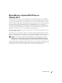
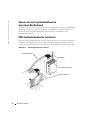
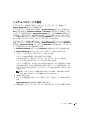
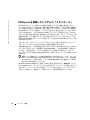
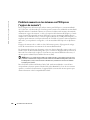
Installing SCSI Hard Drives
When installing SCSI hard drives, you must connect the drives to a SCSI controller card.
See Figure 1-3. The installation illustration in your
Installation and Troubleshooting Guide
shows the drives being connected to the system board.
Figure 1-3. Installing SCSI Hard Drives
power cable
SCSI hard drive
interface cable
SCSI controller card

Information Update 17
Missing Memory in Systems With PCI Express
("Memory Hole")
A condition has been noted on system configurations containing PCI Express slots and RAM of
3.5 GB or greater. The operating system will show an amount of available RAM that is less than the
amount actually installed on the system. The difference of memory, commonly called a "memory
hole," is due to the requirements of the PCI Express subsystem and how memory is allocated by the
system. PCI Express requires RAM in amounts of 256 MB full blocks at a time. Therefore, a
minimum of 256 MB of memory is allotted by the system for PCI Express use, and the allocation
can go higher (in additional blocks of 256 MB) if the system contains additional adapters, either
peripheral or integrated, or if your system supports hot-plug PCI Express.
The memory hole is visible only at the operating system level. The System Setup program reports
the installed RAM correctly.
At this writing, one workaround is available, as reported in the Microsoft Knowledge Base article
#283037 available on Microsoft’s support website. The workaround applies only if your system has
4 GB or more of RAM and your operating system supports Physical Address Extensions (PAE).
NOTICE: You should exercise caution before enabling PAE in your operating system as a number of
problems can occur in certain system configurations. You should search both the Dell and Microsoft
Knowledge Bases for articles detailing these issues and take the appropriate measures to avoid them.
To enable PAE in Microsoft Windows 2000 and 2003, add a
/PAE
switch in the
boot.ini
file to the
line that corresponds to the Windows operating system. For other operating systems, refer to your
documentation or operating system support website for information on PAE support.

18 Information Update
www.dell.com | support.dell.com
Seite wird geladen ...
Seite wird geladen ...
Seite wird geladen ...
Seite wird geladen ...
Seite wird geladen ...
Seite wird geladen ...
Seite wird geladen ...
Seite wird geladen ...
Seite wird geladen ...
Seite wird geladen ...
Seite wird geladen ...
Seite wird geladen ...
Seite wird geladen ...
Seite wird geladen ...
Seite wird geladen ...
Seite wird geladen ...
Seite wird geladen ...
Seite wird geladen ...
Seite wird geladen ...
Seite wird geladen ...
Seite wird geladen ...
Seite wird geladen ...
Seite wird geladen ...
Seite wird geladen ...
Seite wird geladen ...
Seite wird geladen ...
Seite wird geladen ...
Seite wird geladen ...
Seite wird geladen ...
Seite wird geladen ...
Seite wird geladen ...
Seite wird geladen ...
Seite wird geladen ...
Seite wird geladen ...
Seite wird geladen ...
Seite wird geladen ...
Seite wird geladen ...
Seite wird geladen ...
Seite wird geladen ...
Seite wird geladen ...
Seite wird geladen ...
Seite wird geladen ...
Seite wird geladen ...
Seite wird geladen ...
Seite wird geladen ...
Seite wird geladen ...
Seite wird geladen ...
Seite wird geladen ...
Seite wird geladen ...
Seite wird geladen ...
Seite wird geladen ...
Seite wird geladen ...
Seite wird geladen ...
Seite wird geladen ...
Seite wird geladen ...
Seite wird geladen ...
Seite wird geladen ...
Seite wird geladen ...
Seite wird geladen ...
Seite wird geladen ...
Seite wird geladen ...
Seite wird geladen ...
Seite wird geladen ...
Seite wird geladen ...
Seite wird geladen ...
Seite wird geladen ...
Seite wird geladen ...
Seite wird geladen ...
Seite wird geladen ...
Seite wird geladen ...
Seite wird geladen ...
Seite wird geladen ...
Seite wird geladen ...
Seite wird geladen ...
Seite wird geladen ...
Seite wird geladen ...
Seite wird geladen ...
Seite wird geladen ...
Seite wird geladen ...
Seite wird geladen ...
Seite wird geladen ...
Seite wird geladen ...
Seite wird geladen ...
Seite wird geladen ...
Seite wird geladen ...
Seite wird geladen ...
Seite wird geladen ...
Seite wird geladen ...
Seite wird geladen ...
Seite wird geladen ...
Seite wird geladen ...
Seite wird geladen ...
Seite wird geladen ...
Seite wird geladen ...
Seite wird geladen ...
Seite wird geladen ...
Seite wird geladen ...
Seite wird geladen ...
Seite wird geladen ...
Seite wird geladen ...
Seite wird geladen ...
Seite wird geladen ...
Seite wird geladen ...
Seite wird geladen ...
Seite wird geladen ...
Seite wird geladen ...
Seite wird geladen ...
Seite wird geladen ...
Seite wird geladen ...
Seite wird geladen ...
Seite wird geladen ...
Seite wird geladen ...
-
 1
1
-
 2
2
-
 3
3
-
 4
4
-
 5
5
-
 6
6
-
 7
7
-
 8
8
-
 9
9
-
 10
10
-
 11
11
-
 12
12
-
 13
13
-
 14
14
-
 15
15
-
 16
16
-
 17
17
-
 18
18
-
 19
19
-
 20
20
-
 21
21
-
 22
22
-
 23
23
-
 24
24
-
 25
25
-
 26
26
-
 27
27
-
 28
28
-
 29
29
-
 30
30
-
 31
31
-
 32
32
-
 33
33
-
 34
34
-
 35
35
-
 36
36
-
 37
37
-
 38
38
-
 39
39
-
 40
40
-
 41
41
-
 42
42
-
 43
43
-
 44
44
-
 45
45
-
 46
46
-
 47
47
-
 48
48
-
 49
49
-
 50
50
-
 51
51
-
 52
52
-
 53
53
-
 54
54
-
 55
55
-
 56
56
-
 57
57
-
 58
58
-
 59
59
-
 60
60
-
 61
61
-
 62
62
-
 63
63
-
 64
64
-
 65
65
-
 66
66
-
 67
67
-
 68
68
-
 69
69
-
 70
70
-
 71
71
-
 72
72
-
 73
73
-
 74
74
-
 75
75
-
 76
76
-
 77
77
-
 78
78
-
 79
79
-
 80
80
-
 81
81
-
 82
82
-
 83
83
-
 84
84
-
 85
85
-
 86
86
-
 87
87
-
 88
88
-
 89
89
-
 90
90
-
 91
91
-
 92
92
-
 93
93
-
 94
94
-
 95
95
-
 96
96
-
 97
97
-
 98
98
-
 99
99
-
 100
100
-
 101
101
-
 102
102
-
 103
103
-
 104
104
-
 105
105
-
 106
106
-
 107
107
-
 108
108
-
 109
109
-
 110
110
-
 111
111
-
 112
112
-
 113
113
-
 114
114
-
 115
115
-
 116
116
-
 117
117
-
 118
118
-
 119
119
-
 120
120
-
 121
121
-
 122
122
-
 123
123
-
 124
124
-
 125
125
-
 126
126
-
 127
127
-
 128
128
-
 129
129
-
 130
130
-
 131
131
-
 132
132


in anderen Sprachen
- English: Dell PowerEdge SC1420 User guide
- français: Dell PowerEdge SC1420 Mode d'emploi
- español: Dell PowerEdge SC1420 Guía del usuario
- 日本語: Dell PowerEdge SC1420 ユーザーガイド
Verwandte Artikel
-
Dell Latitude 7310 Bedienungsanleitung
-
Dell Latitude 7410 Bedienungsanleitung
-
Dell PowerEdge SC 420 Bedienungsanleitung
-
-
-
-
-
-
-
Dell PowerEdge T100 Benutzerhandbuch