Dell PowerEdge Rack Enclosure 4020S Schnellstartanleitung
- Typ
- Schnellstartanleitung

Dell™ PowerEdge™ 2420
Installation Guide
Guide d’installation
Installationsanleitung
設置ガイド
Guía de instalación


Dell™ PowerEdge™ 2420
Installation Guide

Notes, Cautions, and Warnings
NOTE: A NOTE indicates important information that helps you make better use
of your computer.
CAUTION: A CAUTION indicates potential damage to hardware or loss of data
if instructions are not followed.
WARNING: A WARNING indicates a potential for property damage, personal
injury, or death.
____________________
Information in this document is subject to change without notice.
© 2008 Dell Inc. All rights reserved.
Reproduction of these materials in any manner whatsoever without the written permission of Dell Inc.
is strictly forbidden.
Dell, the DELL logo, and PowerEdge are trademarks of Dell Inc.
Other trademarks and trade names may be used in this document to refer to either the entities claiming
the marks and names or their products. Dell Inc. disclaims any proprietary interest in trademarks and
trade names other than its own.
October 2008 P/N T084M Rev. A00

Contents 3
Contents
Safety Instructions. . . . . . . . . . . . . . . . . . . . . 5
SAFETY: Rack Mounting of Systems
. . . . . . . . . 5
Installation Instructions
. . . . . . . . . . . . . . . . . . 5
Rack Requirements
. . . . . . . . . . . . . . . . . . 6
Rack Installation
. . . . . . . . . . . . . . . . . . . . . . 6
Before You Begin
. . . . . . . . . . . . . . . . . . . 6
Installation Tasks
. . . . . . . . . . . . . . . . . . . 7
Recommended Tools and Supplies
. . . . . . . . . . 7
Removing and Replacing the Rack Doors
. . . . . . 8
Removing and Replacing the Side Panels
. . . . . 11
Reversing the Front Door (optional)
. . . . . . . . 12
Securing the Rack Leveling Feet
. . . . . . . . . . 18
Installing the Rack Stabilizer Feet
. . . . . . . . . 20
Adjusting the Rack Posts (optional)
. . . . . . . . 22
Routing Cables
. . . . . . . . . . . . . . . . . . . 23
Index . . . . . . . . . . . . . . . . . . . . . . . . . . . . . . . 27

4 Contents

Installation Guide 5
Safety Instructions
Use the following safety guidelines to ensure your own personal safety and
to help protect your system and working environment from potential damage.
For complete safety and regulatory information, see the safety instructions
that shipped with your system. Warranty information might be included in
this document or as a separate document.
SAFETY: Rack Mounting of Systems
Observe the following precautions for rack stability and safety. Also refer to
the rack installation documentation accompanying the system and the rack
for specific caution statements and procedures.
Systems are considered to be components in a rack. "Component" refers
to any system as well as to various peripherals or supporting hardware.
CAUTION: Instructions for Rack-Mounted Systems:
• Your rack kit has been approved only for the rack cabinet provided. It is
your responsibility to ensure that installation of the equipment into any
other rack complies with all applicable standards. Dell disclaims all liability
and warranties with respect to combinations of equipment with any other
rack.
• Before installing your equipment in a rack, install all front and side
stabilizers. Failure to install stabilizers can allow the rack to tip over.
• Always load from the bottom up, and load the heaviest items first.
• Do not overload the AC power supply branch circuit that provides power
to the rack.
• Do not stand or step on any components in the rack.
Installation Instructions
This installation guide provides instructions for trained service technicians
installing a 24-unit (U) rack. Information includes assembling the rack
and routing cables through the rack. The 24-U rack can be installed using
the recommended tools.

6 Installation Guide
Rack Requirements
CAUTION: The 24-U rack meets the specifications of American National
Standards Institute (ANSI)/Electronic Industries Association (EIA) standard
ANSI/EIA-310-D-92, Consumer Electronics Association (CEA) Standard CEA-310-E,
International Electrotechnical Commission (IEC) 297, and Deutsche Industrie Norm
(DIN) 41494.
Rack Installation
Before attempting this installation, you should read through this entire
procedure carefully.
Before You Begin
WARNING: Before you begin installing your rack, carefully read "Important
Safety Information," as well as the safety instructions that came with the rack.
WARNING: When installing multiple systems in a rack, complete all of the
procedures for the current system before attempting to install the next system.
WARNING: Rack cabinets can be extremely heavy and move easily on the
casters. The cabinet has no brakes. Use extreme caution while moving the rack
cabinet. Retract the leveling feet when relocating the rack cabinet. Avoid long or
steep inclines, rough surfaces, or ramps where loss of cabinet control may occur.
Extend the leveling feet for support and to prevent the cabinet from rolling.
WARNING: Avoid rolling the rack cabinet over rough surfaces. Hard impacts to
the casters could cause them to break, and the rack could become unstable and
tip over.
WARNING: Do not attempt to move your rack with components installed. If you
move a fully loaded rack on a slightly uneven floor surface, the rack may become
unstable and tip over.
Important Safety Information
Observe the safety precautions in the following subsections when installing
your system in the rack.
WARNING: You must strictly follow the procedures in this document to protect
yourself as well as others who may be involved. Your system may be very large
and heavy, and proper preparation and planning are important to prevent injury
to yourself and to others. This becomes increasingly important when systems
are installed high up in the rack.

Installation Guide 7
WARNING: For stability, you must ensure that a minimum of 50 lbs. is installed
in the bottom 3-U spaces of the rack cabinet.
Rack Stabilizer Feet
WARNING: Installing systems in a rack without the front and side stabilizer feet
installed could cause the rack to tip over, potentially resulting in bodily injury
under certain circumstances. Therefore, always install the stabilizer feet before
installing components in the rack.
WARNING: After installing systems in a rack, never pull more than one system
out of the rack on its slide assemblies at one time. The weight of more than one
extended system could cause the rack to tip over and cause injury.
The stabilizer feet help prevent the rack from tipping over when a system
or other component is pulled out of the rack with the slide assemblies fully
extended.
Installation Tasks
Installing a rack cabinet involves performing the following tasks:
1
Removing and replacing the rack doors
2
Removing and replacing the side panels
3
Reversing the front door and badge (optional)
4
Securing the leveling feet
5
Installing the stabilizer feet
6
Adjusting the rack posts (optional)
7
Routing cables through the rack
Recommended Tools and Supplies
You may need the following tools and supplies to install the rack:
• #2 Phillips screwdriver
• Flat head screwdriver
• 12-mm wrench
• Needle-nose pliers
• 4-mm Allen wrench (if you want to reverse the direction the front
door opens)

8 Installation Guide
• Keys to the rack doors and side panels (included in the rack kit)
• 13-mm wrench (for rack removal from pallet)
• 17-mm wrench (for rack removal from pallet)
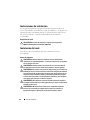
Removing and Replacing the Rack Doors
WARNING: When storing the doors, lay the doors flat so they cannot fall
over and accidentally injure someone.
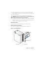
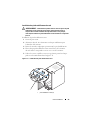
Removing the Front Door
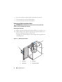
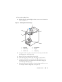
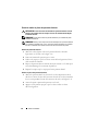
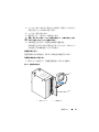
1
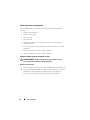
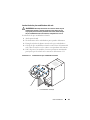
Pull the door latch and open the front door all the way (see Figure 1-1).
2
While holding the door, pull the top hinge pin upward so that it clears
the door’s hinge-pin housing (see Figure 1-1).
The hinge pin’s retention clip prevents the hinge from being pulled out
of the hinge body.
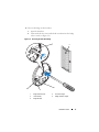
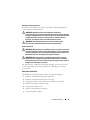
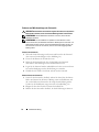
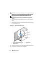
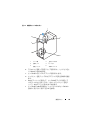
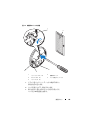
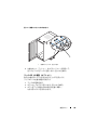
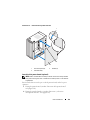
Figure 1-1. Removing the Front Door
1 door latch 2 hinge pin
3 hinge body 4 hinge-pin housing
4
2
3
1

Installation Guide 9
3
While holding the hinge pin out of the door’s hinge-pin housing, pull
the door slightly away from the rack so that the door clears the hinge body.
4
Release the hinge pin.
5
Lift the door upward so that the door clears the bottom hinge post
WARNING: Due to the size and weight of the door, it is recommended that you lay
the removed door flat with the outer surface facing upward.
6
Lay the door in a safe location with the door’s outer surface facing upward.
Laying the door flat with the outer surface facing upward will help prevent
damage to the door’s badge and cosmetic coating.
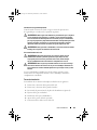
Replacing the Front Door
To replace the front door, perform the steps for removal in reverse.
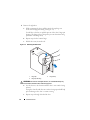
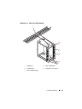
Opening and Removing the Back Doors
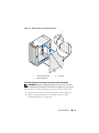
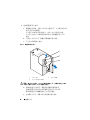
1
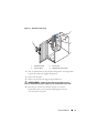
Turn the door handle and open the back doors (see Figure 1-2).
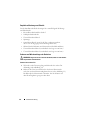
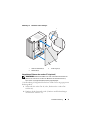
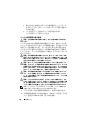
Figure 1-2. Opening the Back Doors
1 door handle 2 back door (2)
1
2

10 Installation Guide
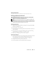
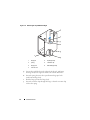
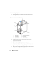
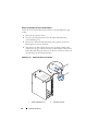
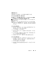
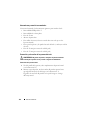
2
Remove the right door.
a
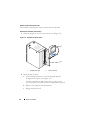
While supporting the door, pull the pin for the top hinge out
of the door’s hinge-pin housing (see Figure 1-3).
You will hear a click as you pull the pin out of the door’s hinge-pin
housing. The hinge pins are designed to prevent them from being
pulled out of the hinge body.
b
Repeat step a for the bottom hinge.
c
Pull the door away from the rack.
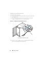
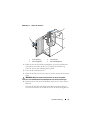
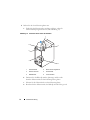
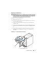
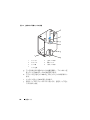
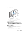
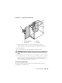
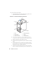
Figure 1-3. Removing the Back Doors
WARNING: Due to the size and weight of the door, it is recommended that you lay
the removed door flat with its outer surface facing upward.
d
Lay the door in a safe location with the door’s outer surface facing
upward.
Laying the door flat with the outer surface facing upward will help
prevent damage to the door’s cosmetic coating.
e
Repeat steps a through d for the left door.
1 hinge pin 2 hinge body
3 hinge-pin housing
1
2
3

Installation Guide 11
Replacing the Back Doors
To replace the back doors, perform the steps for removal in reverse.
Removing and Replacing the Side Panels
CAUTION: Reinstalling the side panels is necessary before running systems
in the rack to ensure proper cooling within the rack.
NOTE: You must remove the side panels in order to install the side stabilizer feet.
NOTE: Although removing the side panels is not mandatory for installing systems in
a rack, having the sides open makes it easier to install slide assemblies and support
rails and to reverse the direction that the front door opens.
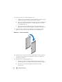
Removing the Side Panels
1
Pull both latches down and allow the side panel to swing outward slightly
at the top (see Figure 1-4).
2
Firmly grasp the sides of the panel.
3
Lift the panel upward until the panel hooks clear the holes in the bottom
of the rack frame.
4
Place the panel in a safe location with the panel’s outer surface facing
upward to help prevent damage to its cosmetic coating.
5
Repeat step 1 through step 4 for the other side panel.
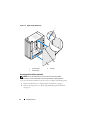
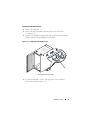
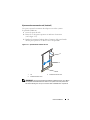
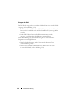
Replacing the Side Panels
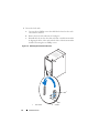
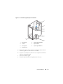
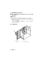
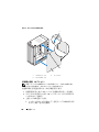
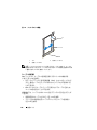
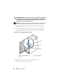
1
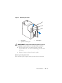
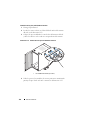
Lower the panel into the rack, inserting the back panel hook into the back
hole in the bottom of the rack frame and the front hook into the
corresponding hole in the front of the rack frame (see Figure 1-4).
2
Swing the top end of the panel towards the rack.
3
Press the panel into the rack until both latches lock into place.

12 Installation Guide
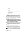
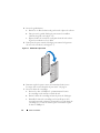
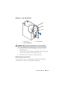
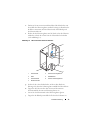
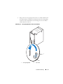
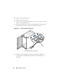
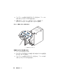
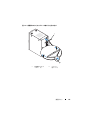
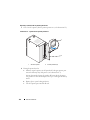
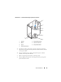
Figure 1-4. Replacing the Side Panels
Reversing the Front Door (optional)
NOTE: Use a 4-mm Allen wrench to remove the front-door hinge bodies
from the rack and reinstall them on the side opposite their original positions.
To reverse the direction that the front door opens, complete the following steps:
1
Remove the front door (see "Removing the Front Door" on page 8).
2
Remove the side panels (see "Removing and Replacing the Side Panels"
on page 11).
1 panel hook (2) 2 latch (2)
3 side panel (2)
3
2
1

Installation Guide 13
3
Reverse the top hinge body.
a
Pull the hinge pin upward slightly so that you can access the retention
clip (see Figure 1-5).
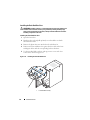
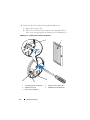
Figure 1-5. Removing the Front-Door Hinges
b
Using the needle-nose pliers, remove the retention clip, and then slide
the hinge pin out of the hinge body.
c
Remove the hinge spring from the hinge body.
d
Place the hinge pin, retention clip, and spring in a safe location.
e
Using the 4-mm Allen wrench, remove the Allen bolts that secure
the hinge body to the rack, and place the bolts with the hinge pin,
retention clip, and body spring.
f
Rotate the hinge body 180 degrees so that the hinge-pin holes are now
on the right side of the hinge body (see Figure 1-6).
1 hinge post 2 top hinge body
3 bottom hinge 4 hinge pin
5 retention clip 6 body spring
4
3
2
5
6
1

14 Installation Guide
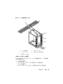
Figure 1-6. Reversing the Top and Bottom Hinges
g
Locate the top bolt holes in the right side of the rack, and fasten
the hinge body to the right side of the rack with the Allen bolts.
h
Insert the spring between the top and bottom hinge-pin holes
in the bottom hinge body.
i
Slide the hinge pin into the hinge body.
j
Insert the retention clip through the hinge so that the retention clip
is below the spring.
1 hinge pin 2 top hinge body
3 spring 4 retention clip
5 hinge post 6 bottom hinge body
7 front of rack
2
3
4
1
5
6
7

Installation Guide 15
4
Reverse the bottom hinge body.
a
Remove the Allen bolts that secure the hinge body to the rack,
and place the bolts in a safe location.
b
Rotate the hinge body 180 degrees so that the hinge posts are now
on the right side of the hinge body (see Figure 1-6).
c
Locate the bottom bolt holes in the right side of the rack, and use
the Allen bolts to fasten the hinge body to the right side of the rack.
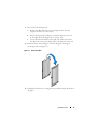
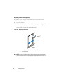
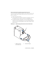
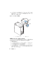
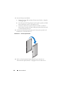
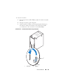
5
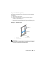
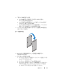
Rotate the front door 180 degrees so that its hinge-pin housings are
on the right side (see Figure 1-7).
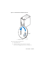
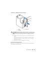
Figure 1-7. Rotate Front Door
6
Rehang the front door by reversing the steps in "Removing the Front Door"
on page 8."

16 Installation Guide
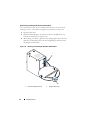
7
Reverse the lock catch.
a
Unscrew the two Phillips screws that hold the lock catch to the rack’s
vertical frame member.
b
Remove the lock catch and rotate it 180 degrees.
c
Reinstall the lock catch on the other rack front vertical frame member
by aligning the holes of the catch with the holes of the frame member
and then reinserting the two Phillips screws.
Figure 1-8. Reversing the Front Door Lock Catch
1 lock catch 2 screws
1
2

Installation Guide 17
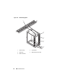
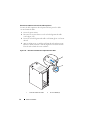
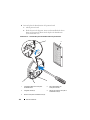
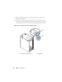
8
Reverse the badge on the front door.
a
Open the front door.
b
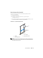
From inside the door, insert a flat-head screwdriver into the badge
release notch (see Figure 1-9).
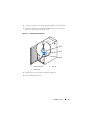
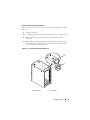
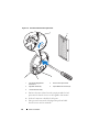
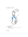
Figure 1-9. Reversing the Front Door Badge
1 badge release notch 2 front door badge
3 center tab (2) 4 badge retention clip (2)
5 badge hook (2)
5
2
1
3
4

18 Installation Guide
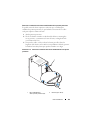
c
Push the screwdriver into the notch until it stops and turn it counter-
clockwise.
d
Lift up on the badge and pull it off the door.
e
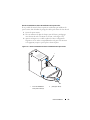
Rotate the badge 180 degrees so that it will read correctly when
reinstalled.
f
Locate the fourth horizontal bar from the top of the door and slide
the badge hooks over it, aligning the center tabs on the badge with
the vertical bar on the door.
g
Push up on the badge retention clips until they are closed and
the badge is secure.
Securing the Rack Leveling Feet
WARNING: Read all statements below before you adjust the leveling feet.
Your rack includes four leveling feet, which are mounted on the corners of
the rack. The leveling feet are designed to align the rack in an upright, level
position when the rack is situated on a slightly uneven floor surface. Before
you install your systems in the rack, deploy and adjust the leveling feet.
When you level your rack, follow these guidelines.
WARNING: When you adjust the leveling feet, ensure that the casters on each
corner of the rack do not rise more than 9.5 mm (3/8 inch) above the floor. If you
exceed 9.5 mm of clearance between the floor and the casters as you adjust the
leveling feet, slowly retract the leveling feet, and then move the rack to another
location that requires minimal adjustments to the leveling feet.
WARNING: Adjust the leveling feet until each leveling foot rests firmly on the
floor. Proper contact with the floor ensures that each leveling foot is supporting
the weight of the rack and prevents the rack from swaying in any direction. If
the leveling feet are not all in firm contact with the floor, the rack can become
unstable and tip over.
WARNING: Do not attempt to move your rack with the leveling feet deployed.
Always retract the leveling feet before moving the rack. Having the leveling feet
deployed when you move the rack may cause the rack to tip over.
WARNING: Always level the rack and install the stabilizing feet before you
install your systems. A fully loaded rack may tip over if your rack is resting on
an uneven floor surface and the leveling and stabilizing feet are not supporting
the weight of the rack.
NOTE: If the rack is not leveled properly, you might not be able to install the
stabilizer feet, which are necessary to prevent the rack from tipping over.
Seite laden ...
Seite laden ...
Seite laden ...
Seite laden ...
Seite laden ...
Seite laden ...
Seite laden ...
Seite laden ...
Seite laden ...
Seite laden ...
Seite laden ...
Seite laden ...
Seite laden ...
Seite laden ...
Seite laden ...
Seite laden ...
Seite laden ...
Seite laden ...
Seite laden ...
Seite laden ...
Seite laden ...
Seite laden ...
Seite laden ...
Seite laden ...
Seite laden ...
Seite laden ...
Seite laden ...
Seite laden ...
Seite laden ...
Seite laden ...
Seite laden ...
Seite laden ...
Seite laden ...
Seite laden ...
Seite laden ...
Seite laden ...
Seite laden ...
Seite laden ...
Seite laden ...
Seite laden ...
Seite laden ...
Seite laden ...
Seite laden ...
Seite laden ...
Seite laden ...
Seite laden ...
Seite laden ...
Seite laden ...
Seite laden ...
Seite laden ...
Seite laden ...
Seite laden ...
Seite laden ...
Seite laden ...
Seite laden ...
Seite laden ...
Seite laden ...
Seite laden ...
Seite laden ...
Seite laden ...
Seite laden ...
Seite laden ...
Seite laden ...
Seite laden ...
Seite laden ...
Seite laden ...
Seite laden ...
Seite laden ...
Seite laden ...
Seite laden ...
Seite laden ...
Seite laden ...
Seite laden ...
Seite laden ...
Seite laden ...
Seite laden ...
Seite laden ...
Seite laden ...
Seite laden ...
Seite laden ...
Seite laden ...
Seite laden ...
Seite laden ...
Seite laden ...
Seite laden ...
Seite laden ...
Seite laden ...
Seite laden ...
Seite laden ...
Seite laden ...
Seite laden ...
Seite laden ...
Seite laden ...
Seite laden ...
Seite laden ...
Seite laden ...
Seite laden ...
Seite laden ...
Seite laden ...
Seite laden ...
Seite laden ...
Seite laden ...
Seite laden ...
Seite laden ...
Seite laden ...
Seite laden ...
Seite laden ...
Seite laden ...
Seite laden ...
Seite laden ...
Seite laden ...
Seite laden ...
Seite laden ...
Seite laden ...
Seite laden ...
Seite laden ...
Seite laden ...
Seite laden ...
Seite laden ...
Seite laden ...
Seite laden ...
Seite laden ...
Seite laden ...
Seite laden ...
Seite laden ...
Seite laden ...
Seite laden ...
Seite laden ...
-
 1
1
-
 2
2
-
 3
3
-
 4
4
-
 5
5
-
 6
6
-
 7
7
-
 8
8
-
 9
9
-
 10
10
-
 11
11
-
 12
12
-
 13
13
-
 14
14
-
 15
15
-
 16
16
-
 17
17
-
 18
18
-
 19
19
-
 20
20
-
 21
21
-
 22
22
-
 23
23
-
 24
24
-
 25
25
-
 26
26
-
 27
27
-
 28
28
-
 29
29
-
 30
30
-
 31
31
-
 32
32
-
 33
33
-
 34
34
-
 35
35
-
 36
36
-
 37
37
-
 38
38
-
 39
39
-
 40
40
-
 41
41
-
 42
42
-
 43
43
-
 44
44
-
 45
45
-
 46
46
-
 47
47
-
 48
48
-
 49
49
-
 50
50
-
 51
51
-
 52
52
-
 53
53
-
 54
54
-
 55
55
-
 56
56
-
 57
57
-
 58
58
-
 59
59
-
 60
60
-
 61
61
-
 62
62
-
 63
63
-
 64
64
-
 65
65
-
 66
66
-
 67
67
-
 68
68
-
 69
69
-
 70
70
-
 71
71
-
 72
72
-
 73
73
-
 74
74
-
 75
75
-
 76
76
-
 77
77
-
 78
78
-
 79
79
-
 80
80
-
 81
81
-
 82
82
-
 83
83
-
 84
84
-
 85
85
-
 86
86
-
 87
87
-
 88
88
-
 89
89
-
 90
90
-
 91
91
-
 92
92
-
 93
93
-
 94
94
-
 95
95
-
 96
96
-
 97
97
-
 98
98
-
 99
99
-
 100
100
-
 101
101
-
 102
102
-
 103
103
-
 104
104
-
 105
105
-
 106
106
-
 107
107
-
 108
108
-
 109
109
-
 110
110
-
 111
111
-
 112
112
-
 113
113
-
 114
114
-
 115
115
-
 116
116
-
 117
117
-
 118
118
-
 119
119
-
 120
120
-
 121
121
-
 122
122
-
 123
123
-
 124
124
-
 125
125
-
 126
126
-
 127
127
-
 128
128
-
 129
129
-
 130
130
-
 131
131
-
 132
132
-
 133
133
-
 134
134
-
 135
135
-
 136
136
-
 137
137
-
 138
138
-
 139
139
-
 140
140
-
 141
141
-
 142
142
-
 143
143
-
 144
144
-
 145
145
-
 146
146
-
 147
147
-
 148
148


