Yamaha MLA-200 Installationsanleitung

Typ
Installationsanleitung
MLA-200
MUSIC LABORATORY SYSTEM
Installation Guide
EN
2 Music Laboratory System Installation Guide
Contents
Introduction .........................................................................................3
Overview of the Music Laboratory System................................................................. 3
Preparations............................................................................................................... 3
Workflow .................................................................................................................... 4
1. Trial setup.....................................................................................5
2. Setting up the wireless access point (DHCP server) ...............5
3. Setting up MLA-200s ...................................................................7
4. Setting up MRX7-Ds ..................................................................11
5. Setting up the audio network ...................................................14
6. Setting up ML Touch .................................................................18
7. Connecting audio devices ........................................................19
8. Operation check.........................................................................20
9. Installing onto an instrument ...................................................21
Installation precautions (attaching to the instrument with included screws)............. 21
Installation procedure............................................................................................... 21
Installation examples................................................................................................ 23
When placed on a flat surface.................................................................................. 25
10. Final operation check................................................................26
11. Troubleshooting ........................................................................27
Music Laboratory System Installation Guide 3
Introduction
Overview of the Music Laboratory System
The Yamaha Music Laboratory System is a music education system that combines Yamaha’s
abundant know-how in music education and electronics technology. This system is built to support
communication between students and instructors and to provide more fluid guidance on individual and
group performances. Instructors can use the application on an iPad to operate the entire system, such
as checking students’ performances, responding to questions and sending performance data.
This system combines MRX7-D as the core of the audio network and MLA-200 (with a master unit for
the instructor and subordinate units for the students). Up to 24 subordinate units for students can be
connected to one MRX7-D. At maximum, a system can be built to connect 96 subordinate units with
four MRX7-Ds.
This Setup Guide provides the necessary information for building and setting up the Music Laboratory
System in a classroom. We recommend that you read this information before and during setup.
Preparations
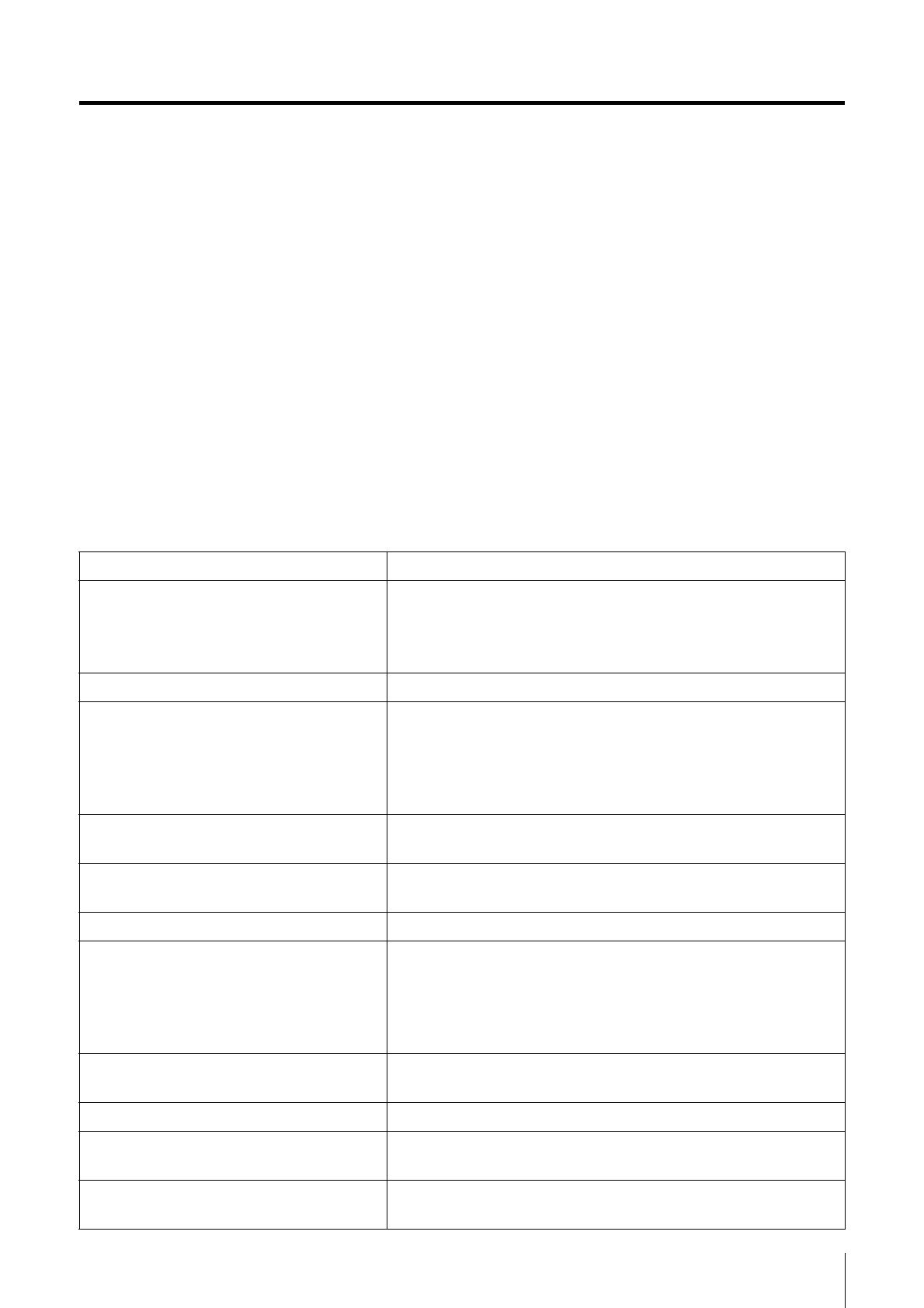
Items necessary for building the system
MLA-200 One for the instructor and a maximum of 96 for students.
MRX7-D
A maximum of one MLA-200 for the instructor and 24
MLA-200s for students can be connected to one MRX7-D.
Up to four MRX7-Ds can be connected.
Insert the SD Memory Card into all MRX7-Ds.
PoE powered Ethernet switch A power supply of 6 W or more per port is required.
STP Ethernet cables
STP cables must be of CAT5e (1000BASE-T) or higher
grade.
Prepare a total number of cables equal to the number of
MLA-200s + the number of MRX7-Ds × 2 + the computer
+ the wireless access point + the Ethernet switch.
USB cable (Type AB)
Use to communicate MIDI data with the instrument.
Prepare the same number as MLA-200s.
Audio cable
Use to connect the instrument and MLA-200. Prepare
stereo cables with standard headphones plugs.
Headphones/microphone headset With 3.5 mm mini plugs (CTIA compliant)
Wireless access point/DHCP server
Use for communication between the iPad application and
the hardware.
This device must be able to perform the DHCP server
function of assigning addresses to both wireless devices
and LAN devices.
Audio playback device
Use a CD player, etc., to play back audio teaching
materials.
Microphone For audio input by the instructor.
iPad
Use to operate the “ML Touch” control application for the
instructor. iOS 12 or later is required.
ML Touch
This iPad application for instructors can be obtained for free
from the App Store.
4 Music Laboratory System Installation Guide
Items necessary only for setup
Workflow
Follow the workflow below to build and set up the Music Laboratory System.
Windows computer
Use to specify settings during setup. A computer with an RJ45 connector
and running Windows 10, Windows 8.1 or Windows 7 is required.
MTX-MRX Editor
Use to transfer the MRX7-D setup file data to MRX7-D when specifying
settings during setup. Install this application on a Windows computer. For
details on the installation and settings, refer to the MRX Setup Manual.
MRX7-D setup file
This file provides the settings for the Music Laboratory System. One file
per MRX7-D used is required.
ML Config Tool
This software automatically configures the audio network connection
between the MRX7-Ds and MLA-200s. Install this software on a Windows
computer.
Dante Controller
Use to change the audio network setup manually (for special settings) and
to check the status of the system.
1. Trial setup
2. Setting up the wireless access
point (DHCP server)
3. Setting up MLA-200s
4. Setting up MRX7-Ds
5. Setting up the audio network
6. Setting up ML Touch
7. Connecting audio devices
8. Operation check
9. Installing the MLA-200 onto the
instrument
10. Final operation check
Music Laboratory System Installation Guide 5
1. Trial setup
Before installing the devices in the classroom, perform a trial setup of the entire system to check the
setup and operation of each device.
Since it will be difficult to remove and attach the DIP switch cover and change the DIP switch settings
after the MLA-200 is installed onto an instrument, we recommend checking the setup and operation of
each device beforehand.
The “ML Touch” application for the instructor communicates with each device via Wi-Fi. For that
reason, the network must include a wireless access point.
The wireless access point used here must be able to perform the DHCP server function of assigning
addresses to both wireless devices and LAN devices.
Connect the wireless access point to the Windows computer, and then set it up.
2-1.
Connect the computer and wireless access point with an Ethernet cable.
2-2. Specify the IP address of the computer.
For example, if the network setting of the wireless access point contains an IP address of
“192.168.100.240” and subnet mask of “255.255.255.0”, specify the following settings in the
“Internet Protocol Version 4 (TCP/IPv4) Properties” dialog box of “Network and Sharing Center”
in the Windows Control Panel.
After specifying the settings, click the “OK” button in each dialog box.
2. Setting up the wireless access point (DHCP server)
Example)
IP address 192.168.100.1
(Use the IP address of the wireless access point up to
“192.168.100”, and then add “1” at the end.)
Subnet mask 255.255.255.0
6 Music Laboratory System Installation Guide
2. Setting up the wireless access point (DHCP server)
2-3. Change the settings for the wireless access point (DHCP server).
Start the browser (Internet Explorer, etc.), and then type “http://192.168.100.240/” (with the
default IP address of the wireless access point being “192.168.100.240”) to access the setup
screen for the wireless access point. Use the default IP address of the wireless access point. In
addition, some types of wireless access points may have a dedicated application or unique
address.
Refer to the manual for the wireless access point, and then specify the following settings.
LAN port settings
NOTE
If the DHCP server is assigned an address other than those listed above, there may be a conflict with the
IP address used by the Music Laboratory System and the server may not work properly.
2-4. Change the IP address of the computer.
Change the IP address specified in step 2-2. to one for an MRX7-D setup.
Select “Obtain an IP address automatically” in the “Internet Protocol Version 4 (TCP/IPv4)
Properties” dialog box of “Network and Sharing Center” in the Windows Control Panel.
After selecting the setting, click the “OK” button.
This completes the setup of the wireless access point.
DHCP server function ON
Assigned address 192.168.0.110 to 192.168.0.240
DHCP lease timeout Never (maximum)
IP address (IPv4) 192.168.0.254
Subnet mask 255.255.255.0
Music Laboratory System Installation Guide 7
3. Setting up MLA-200s
Each MLA-200 in an audio network is differentiated by the unique ID that is specified.
Specify this ID with the DIP switch.
3-1. With nothing connected, open the DIP switch cover on the rear panel.
One side of the cover remains attached. Disengage the side that does not remain attached,
and then slowly open the cover.
3-2. Set the DIP switch.
The switches of the DIP switch are set to ON when it is down and OFF when it is up. As a
default, all switches are set to OFF (up).
NOTE
Be sure to view the DIP switch in its proper orientation.
Set the DIP switch for each MLA-200 according to the following table.
Instructor and students 1 to 24 (MRX7-D ID=1)
SW
1 2 3 4 5 6 7 8
Instructor (ID=1) OFF OFF OFF OFF OFF OFF OFF
ON
Student 1 (ID=2) OFF OFF OFF OFF OFF OFF
ON OFF
Student 2 (ID=3) OFF OFF OFF OFF OFF OFF
ON ON
Student 3 (ID=4) OFF OFF OFF OFF OFF
ON OFF OFF
Student 4 (ID=5) OFF OFF OFF OFF OFF
ON OFF ON
Student 5 (ID=6) OFF OFF OFF OFF OFF
ON ON OFF
Student 6 (ID=7) OFF OFF OFF OFF OFF
ON ON ON
Student 7 (ID=8) OFF OFF OFF OFF
ON OFF OFF OFF
Student 8 (ID=9) OFF OFF OFF OFF
ON OFF OFF ON
DIP switch cover
8 Music Laboratory System Installation Guide
3. Setting up MLA-200s
Students 25 to 48 (MRX7-D ID=2)
Student 9 (ID=10) OFF OFF OFF OFF ON OFF ON OFF
Student 10 (ID=11) OFF OFF OFF OFF
ON OFF ON ON
Student 11 (ID=12) OFF OFF OFF OFF
ON ON OFF OFF
Student 12 (ID=13) OFF OFF OFF OFF
ON ON OFF ON
Student 13 (ID=14) OFF OFF OFF OFF
ON ON ON OFF
Student 14 (ID=15) OFF OFF OFF OFF
ON ON ON ON
Student 15 (ID=16) OFF OFF OFF
ON OFF OFF OFF OFF
Student 16 (ID=17) OFF OFF OFF
ON OFF OFF OFF ON
Student 17 (ID=18) OFF OFF OFF
ON OFF OFF ON OFF
Student 18 (ID=19) OFF OFF OFF
ON OFF OFF ON ON
Student 19 (ID=20) OFF OFF OFF
ON OFF ON OFF OFF
Student 20 (ID=21) OFF OFF OFF
ON OFF ON OFF ON
Student 21 (ID=22) OFF OFF OFF
ON OFF ON ON OFF
Student 22 (ID=23) OFF OFF OFF
ON OFF ON ON ON
Student 23 (ID=24) OFF OFF OFF
ON ON OFF OFF OFF
Student 24 (ID=25) OFF OFF OFF
ON ON OFF OFF ON
SW
1 2 3 4 5 6 7 8
Student 25 (ID=26) OFF OFF OFF
ON ON OFF ON OFF
Student 26 (ID=27) OFF OFF OFF
ON ON OFF ON ON
Student 27 (ID=28) OFF OFF OFF
ON ON ON OFF OFF
Student 28 (ID=29) OFF OFF OFF
ON ON ON OFF ON
Student 29 (ID=30) OFF OFF OFF
ON ON ON ON OFF
Student 30 (ID=31) OFF OFF OFF
ON ON ON ON ON
Student 31 (ID=32) OFF OFF
ON OFF OFF OFF OFF OFF
Student 32 (ID=33) OFF OFF
ON OFF OFF OFF OFF ON
Student 33 (ID=34) OFF OFF
ON OFF OFF OFF ON OFF
Student 34 (ID=35) OFF OFF
ON OFF OFF OFF ON ON
Student 35 (ID=36) OFF OFF
ON OFF OFF ON OFF OFF
Student 36 (ID=37) OFF OFF
ON OFF OFF ON OFF ON
Student 37 (ID=38) OFF OFF
ON OFF OFF ON ON OFF
Student 38 (ID=39) OFF OFF
ON OFF OFF ON ON ON
Student 39 (ID=40) OFF OFF
ON OFF ON OFF OFF OFF
Student 40 (ID=41) OFF OFF
ON OFF ON OFF OFF ON
Music Laboratory System Installation Guide 9
3. Setting up MLA-200s
Students 49 to 72 (MRX7-D ID=3)
Student 41 (ID=42) OFF OFF ON OFF ON OFF ON OFF
Student 42 (ID=43) OFF OFF
ON OFF ON OFF ON ON
Student 43 (ID=44) OFF OFF
ON OFF ON ON OFF OFF
Student 44 (ID=45) OFF OFF
ON OFF ON ON OFF ON
Student 45 (ID=46) OFF OFF
ON OFF ON ON ON OFF
Student 46 (ID=47) OFF OFF
ON OFF ON ON ON ON
Student 47 (ID=48) OFF OFF
ON ON OFF OFF OFF OFF
Student 48 (ID=49) OFF OFF
ON ON OFF OFF OFF ON
SW
1 2 3 4 5 6 7 8
Student 49 (ID=50) OFF OFF
ON ON OFF OFF ON OFF
Student 50 (ID=51) OFF OFF
ON ON OFF OFF ON ON
Student 51 (ID=52) OFF OFF
ON ON OFF ON OFF OFF
Student 52 (ID=53) OFF OFF
ON ON OFF ON OFF ON
Student 53 (ID=54) OFF OFF
ON ON OFF ON ON OFF
Student 54 (ID=55) OFF OFF
ON ON OFF ON ON ON
Student 55 (ID=56) OFF OFF
ON ON ON OFF OFF OFF
Student 56 (ID=57) OFF OFF
ON ON ON OFF OFF ON
Student 57 (ID=58) OFF OFF
ON ON ON OFF ON OFF
Student 58 (ID=59) OFF OFF
ON ON ON OFF ON ON
Student 59 (ID=60) OFF OFF
ON ON ON ON OFF OFF
Student 60 (ID=61) OFF OFF
ON ON ON ON OFF ON
Student 61 (ID=62) OFF OFF
ON ON ON ON ON OFF
Student 62 (ID=63) OFF OFF
ON ON ON ON ON ON
Student 63 (ID=64) OFF
ON OFF OFF OFF OFF OFF OFF
Student 64 (ID=65) OFF
ON OFF OFF OFF OFF OFF ON
Student 65 (ID=66) OFF
ON OFF OFF OFF OFF ON OFF
Student 66 (ID=67) OFF
ON OFF OFF OFF OFF ON ON
Student 67 (ID=68) OFF
ON OFF OFF OFF ON OFF OFF
Student 68 (ID=69) OFF
ON OFF OFF OFF ON OFF ON
Student 69 (ID=70) OFF
ON OFF OFF OFF ON ON OFF
Student 70 (ID=71) OFF
ON OFF OFF OFF ON ON ON
Student 71 (ID=72) OFF
ON OFF OFF ON OFF OFF OFF
Student 72 (ID=73) OFF
ON OFF OFF ON OFF OFF ON
10 Music Laboratory System Installation Guide
3. Setting up MLA-200s
Students 73 to 96 (MRX7-D ID=4)
This completes the setup of the MLA-200s.
SW
1 2 3 4 5 6 7 8
Student 73 (ID=74) OFF
ON OFF OFF ON OFF ON OFF
Student 74 (ID=75) OFF
ON OFF OFF ON OFF ON ON
Student 75 (ID=76) OFF
ON OFF OFF ON ON OFF OFF
Student 76 (ID=77) OFF
ON OFF OFF ON ON OFF ON
Student 77 (ID=78) OFF
ON OFF OFF ON ON ON OFF
Student 78 (ID=79) OFF
ON OFF OFF ON ON ON ON
Student 79 (ID=80) OFF
ON OFF ON OFF OFF OFF OFF
Student 80 (ID=81) OFF
ON OFF ON OFF OFF OFF ON
Student 81 (ID=82) OFF
ON OFF ON OFF OFF ON OFF
Student 82 (ID=83) OFF
ON OFF ON OFF OFF ON ON
Student 83 (ID=84) OFF
ON OFF ON OFF ON OFF OFF
Student 84 (ID=85) OFF
ON OFF ON OFF ON OFF ON
Student 85 (ID=86) OFF
ON OFF ON OFF ON ON OFF
Student 86 (ID=87) OFF
ON OFF ON OFF ON ON ON
Student 87 (ID=88) OFF
ON OFF ON ON OFF OFF OFF
Student 88 (ID=89) OFF
ON OFF ON ON OFF OFF ON
Student 89 (ID=90) OFF
ON OFF ON ON OFF ON OFF
Student 90 (ID=91) OFF
ON OFF ON ON OFF ON ON
Student 91 (ID=92) OFF
ON OFF ON ON ON OFF OFF
Student 92 (ID=93) OFF
ON OFF ON ON ON OFF ON
Student 93 (ID=94) OFF
ON OFF ON ON ON ON OFF
Student 94 (ID=95) OFF
ON OFF ON ON ON ON ON
Student 95 (ID=96) OFF
ON ON OFF OFF OFF OFF OFF
Student 96 (ID=97) OFF
ON ON OFF OFF OFF OFF ON
Music Laboratory System Installation Guide 11
4. Setting up MRX7-Ds
The MRX7-D is the core of the Music Laboratory System and controls the audio network.
Twenty-four MLA-200s for students can be connected to one MRX7-D. By using four MRX7-Ds in one
audio network, one MLA-200 for the instructor and a maximum of ninety-six MLA-200s for students
can be connected.
Each MRX7-D in an audio network is differentiated by the unique ID that is specified. ID=1 is used for
the instructor and students 1 to 24, ID=2 for students 25 to 48, ID=3 for students 49 to 72, and ID=4 for
students 73 to 96.
The MRX7-Ds are set up using MTX-MRX Editor, installed on the Windows computer. Open the
MRX7-D setup file in MTX-MRX Editor, and then load it onto the MRX7-D to complete the setup.
For details on the installation and settings of MTX-MRX Editor, refer to the MRX Setup Manual.
4-1. Before turning on MRX7-D, set the rotary switch and DIP switch.
Specify the following settings.
MRX7-D ID=1 (instructor and students 1 to 24)
Rotary switch=1, DIP switch=All switches set to OFF (up)
MRX7-D ID=2 (students 25 to 48)
Rotary switch=2, DIP switch=All switches set to OFF (up)
MRX7-D ID=3 (students 49 to 72)
Rotary switch=3, DIP switch=All switches set to OFF (up)
MRX7-D ID=4 (students 73 to 96)
Rotary switch=4, DIP switch=All switches set to OFF (up)
12 Music Laboratory System Installation Guide
4. Setting up MRX7-Ds
4-2. Using an Ethernet cable, connect the Windows computer installed
wi
th MTX-MRX Editor and the MRX7-Ds to be set up.
Connection diagram
With the Ethernet switch in the center, connect the wireless access point (DHCP server) and
MRX7-Ds with Ethernet cables. The MRX7-Ds connect daisy chain in order from ID=1.
When using multiple MRX7-Ds, they must be connected via the YDIF ports. The connections
between the ports are as follows.
YDIF OUT port of MRX7-D ID=1 YDIF IN port of MRX7-D ID=2
YDIF OUT port of MRX7-D ID=2 YDIF IN port of MRX7-D ID=3
YDIF OUT port of MRX7-D ID=3 YDIF IN port of MRX7-D ID=4
YDIF OUT port of MRX7-D ID=4 YDIF IN port of MRX7-D ID=1
When there are two, connect the YDIF OUT port of ID=2 to the YDIF IN port of ID=1. When
there are three, connect the YDIF OUT port of ID=3 to the YDIF IN port of ID=1.
4-3. Turn on MRX7-D.
4-4. Start MTX-MRX Editor on the Windows computer.
4-5. In MTX-MRX Editor, select “File” menu “Open”, and then open the
previously downloaded MRX7-D setup file.
The file to be opened differs depending on the number of MRX7-Ds that are connected. Select
the setup file according to the number of devices in the system.
Computer
Wireless access point
(DHCP server)
PoE powered
Ethernet switch
MRX7-D ID=1
MRX7-D ID=2
MRX7-D ID=3
MRX7-D ID=4
Music Laboratory System Installation Guide 13
4. Setting up MRX7-Ds
4-6. In MTX-MRX Editor, select “System” menu “Network Setup”, and
then select the name of the network card of the computer.
At this time, a dialog box appears if the firmware of MRX7-D is not a compatible version for
MTX-MRX Editor. Follow the on-screen instructions to update the firmware.
4-7. Click the “ONLINE” button in the upper-right corner of MTX-MRX
Editor.
The Synchronization dialog box appears.
4-8. Select the “To Device” check box, and then click the “OK” button.
A different dialog box appears.
4-9. Select the check box for the system to be put online, and then click
the “ONLINE” button.
The MRX7-D setup is loaded. When loading is completed, the dialog box closes automatically.
This completes the setup of the MRX7-Ds.
14 Music Laboratory System Installation Guide
5. Setting up the audio network
Communications between the instructor and students as well as audio of the performance is sent and
received through the audio network. In the Music Laboratory System, Dante has been adopted as the
structure of the audio network. Although software called Dante Controller is normally used to set up a
Dante audio network, its high degree of flexibility requires knowledge about audio networks.
Therefore, the dedicated software ML Config Tool is used in the Music Laboratory System to make
setup easier. Be sure to copy ML Config Tool beforehand onto the Windows computer that was using
MTX-MRX Editor.
NOTE
In the Dante audio network of the Music Laboratory System, both the ID number and MAC address (physical
address) of each device are used to control communication. Therefore, the audio network must be set up in all of
the following cases.
The system is installed for the first time.
The number of MLA-200s or MRX7-Ds is increased or decreased.
The ID of a device is changed with the DIP switch.
A device is replaced.
Music Laboratory System Installation Guide 15
5. Setting up the audio network
5-1. Connect all MLA-200s to Ethernet switches.
The [STATUS] indicator flashes while the device is starting up. The indicator lights up when the
device is finished starting up.
Check that the [STATUS] indicator of all MLA-200s are lit.
Connection diagram
NOTE
Before making connections, be sure to complete the procedure in “3. Setting up MLA-200s” (Page 7).
The changes to the DIP switch settings are applied when the Ethernet cable is connected and the
MLA-200 is turned on. Before changing the settings, unplug the Ethernet cable from the MLA-200.
The Ethernet switches and MLA-200s can be connected in any configuration, depending on the layout
of the classroom.
In a system with a large number of students, it may take some time for all [STATUS] indicators to light
up after the MLA-200 (ID=1) for the instructor is finished starting up.
When connecting the Windows computer used for setup, be sure to plug an Ethernet cable into the
computer’s built-in RJ45 network connector.
Computer
Wireless access
point
(DHCP server)
PoE powered
Ethernet switch
MLA-200
ID=1
(Instructor)
MLA-200
ID=2
(Student 1)
MLA-200
ID=3
(Student 2)
MLA-200
ID=4
(Student 3)
MLA-200
ID=10
(Student 9)
MLA-200
ID=11
(Student 10)
MLA-200
ID=12
(Student 11)
MLA-200
ID=xx
(Student xx)
MLA-200
ID=yy
(Student yy)
MLA-200
ID=zz
(Student zz)
MLA-200
ID=89
(Student 88)
MLA-200
ID=90
(Student 89)
MLA-200
ID=91
(Student 90)
PoE powered
Ethernet switch
PoE powered
Ethernet switch
PoE powered
Ethernet switch
PoE powered
Ethernet switch
MRX7-D ID=1
MRX7-D ID=2
MRX7-D ID=3
MRX7-D ID=4
16 Music Laboratory System Installation Guide
5. Setting up the audio network
5-2. Before starting the ML Config Tool, in the Control Panel of the
Windows computer, disable all network adapters (including Wi-Fi)
except the one for the built-in RJ45 connector connection.
Make sure that only the wired network adapter connected to the Music Laboratory System is
enabled.
5-3. Start the ML Config Tool installed onto the Windows computer.
A window appears.
5-4.
In “The number of MRX7-D” box, type the number of MRX7-Ds to be used.
5-5. In “The number of MLA-200” box, type the number of MLA-200s
connected for each MRX7-D ID.
For example, if there is one MRX7-D, only “Area #1” will be available.
Include the MLA-200 for the instructor with the number of devices for Area #1. Area #1 can be
set between 2 (for 1 instructor + 1 student) and 25 (for 1 instructor + 24 students); Area #2 to #4
can be set between 1 (for 1 student) and 24 (for 24 students).
Music Laboratory System Installation Guide 17
5. Setting up the audio network
5-6. Click the “Confirm” button.
The software automatically checks that the MRX7-Ds and MLA-200s are correctly set up. If
they are correctly set up, “Succeed” appears in the “Output” box on the right side of the window.
If this does not appear, return to the previous steps and check each of the settings.
5-7. Check that “Succeed” appears, and then click the “Apply” button.
This completes the setup of the audio network.
18 Music Laboratory System Installation Guide
6. Setting up ML Touch
ML Touch is an iPad application used by instructors to operate the entire system. It can be
downloaded from the App Store.
This describes the setup operations that must be performed before the application can be used. For
details on using ML Touch, refer to the ML Touch User’s Guide.
6-1. Download ML Touch from the App Store.
6-2. Tap the ML Touch icon to start the application.
The initial setup window appears.
Then, if there are no problems, the Home window appears.
If an error appears, check the following.
Are the MRX7-Ds connected and set up correctly?
Are the MLA-200s connected correctly and are there no duplicate IP addresses?
If an error appeared, the Home window does not appear. Exit ML Touch, and then start it again.
If the iPad is not connected via Wi-Fi, make settings in iOS.
This completes the setup of ML Touch.
Music Laboratory System Installation Guide 19
7. Connecting audio devices
Connect audio devices, such as the instructor’s microphone or a CD player used for teaching, to the
MRX7-D set to ID=1.
7-1. Turn off all devices to be connected.
7-2 . Connect the audio devices as shown above.
Use the Euroblock connectors on the MRX7-D to make connections for the microphone input
and power amplifier (powered speakers). For details on using the Euroblock connectors, refer
to “Euroblock plug connection” in the MRX7-D Owner’s Manual.
When using multiple MRX7-Ds, connect them via their YDIF ports.
7-3 . Turn on the MRX7-Ds.
When using multiple MRX7-Ds, turn them on in order, starting with ID=1.
7-4 . Turn on the power amplifier (powered speakers).
7-5 . Start ML Touch.
7-6 . Adjust the volume of the power amplifier.
At this time, adjust the volume to check that the connection has been made.
NOTE
Use the Euroblock connectors on the
MRX7-D to make the microphone
input and speaker output connections.
CD/BD player 2 CD/BD player 1
Power
amplifier
(YDIF port of MRX7-D)
Indoor speaker RIndoor speaker L
MRX7-D ID=1
PoE powered
Ethernet switch
MRX7-D ID=2
20 Music Laboratory System Installation Guide
7. Connecting audio devices / 8. Operation check
7-7 . Use ML Touch to check that sound from the microphone or CD player
is output from the speakers.
If no sound is output, return to the previous steps and perform each one again.
This completes the connection of the audio devices.
After completing this trial setup, check communication with MLA-200s for students.
8-1. Turn on all connected devices.
8-2. Start ML Touch.
8-3. Perform each function to check that it operates correctly.
For details on operating ML Touch, refer to the ML Touch User’s Guide.
The operation check is completed when communication with all MLA-200s can be performed correctly.
8. Operation check
  • Page 1 1
  • Page 2 2
  • Page 3 3
  • Page 4 4
  • Page 5 5
  • Page 6 6
  • Page 7 7
  • Page 8 8
  • Page 9 9
  • Page 10 10
  • Page 11 11
  • Page 12 12
  • Page 13 13
  • Page 14 14
  • Page 15 15
  • Page 16 16
  • Page 17 17
  • Page 18 18
  • Page 19 19
  • Page 20 20
  • Page 21 21
  • Page 22 22
  • Page 23 23
  • Page 24 24
  • Page 25 25
  • Page 26 26
  • Page 27 27
  • Page 28 28

Yamaha MLA-200 Installationsanleitung

Typ
Installationsanleitung