
MH 198 RKS - MZ 2098 RKS - 205S - 105S
English is original instructions, other language is translation of original instructions
Pubbl. 68580024 - Set/2018
I
D
F
GB
E
SK
OWNER’S MANUAL
MANUALE USO E MANUTENZIONE
BETRIEBS- UND WARTUNGSANLEITUNG
MANUEL D’UTILISATION ET D’ENTRETIEN
MANUAL DE USO Y MANTENIMIENTO
NÁVOD NA POUŽITIE A ÚDRŽBU

2
ATTENZIONE!!! ACHTUNG!!!
RISCHIO DI DANNO UDITIVO
NELLE NORMALI CONDIZIONI DI UTILIZZO,
QUESTA MACCHINA PUÒ COMPORTARE
PER L’OPERATORE ADDETTO, UN LIVELLO DI
ESPOSIZIONE PERSONALE E GIORNALIERO
A RUMORE PARI O SUPERIORE A
85 dB(A)
HÖRSCHADEN - RISIKO
UNTER NORMALEN ANWENDUNGSBEDIGUNGEN
KANN DIESES GERÄT DIE BEDIENUNGSPERSON
EINEM TÄGLICHEN GERÄUSCHPEGEL VON
85 dB(A)
ODER MEHR AUSSETZEN
WARNING!!! ATENCION!!!
RISK OF DAMAGING HEARING
IN NORMAL CONDITIONS OF USE,
THIS MACHINE MAY INVOLVE A DAILY LEVEL
OF PERSONAL EXPOSURE TO NOISE
FOR THE OPERATOR EQUAL TO
OR GREATER THAN
85 dB(A)
RIESGO DE DAÑO AUDITIVO
EN NORMALES CONDICIONES DE UTILIZACIÓN,
ESTA MAQUINA PUEDE TOLERAR, PARA EL OPERADOR
ENCARGADO, UN NIVEL DE EXPOSICÍON
DIARIO A RUIDO EQUIVALENTE O SUPERIOR A
85 dB(A)
ATTENTION!!!
POZOR!!!
DANGER D’ATTEINTE A L’OUIE
L’OPERATEUR UTILISANT NORMALEMENT
CETTE MACHINE PEUTS S’EXPOSER
QUOTIDIENNEMENT A UN BRUIT
EGAL OU DEPASSANT
85 dB(A)
RIZIKO POŠKODENIA SLUCHU
ZA BEŽNÝCH PRACOVNÝCH PODMIENOK MÔŽE TENTO
STROJ PREDSTAVOVAŤ PRE PRACOVNÍKA VYSTAVENIE
DENNEJ HLADINE A OSOBNEJ HLADINE HLUKU
ROVNAJÚCEJ SA ALEBO VYŠŠEJ AKO
85 dB(A)
I
INTRODUZIONE
ISTRUZIONI ORIGINALI
Per un corretto impiego della motozappa e per evitare incidenti, non iniziare il lavoro senza aver
letto questo manuale con la massima attenzione. Su questo manuale sono indicate le spiegazioni di
funzionamento dei vari componenti e le istruzioni per i necessari controlli e per la manutenzione.
N.B. Le descrizioni e le illustrazioni contenute nel presente manuale si intendono non
rigorosamente impegnative. La Ditta si riserva il diritto di apportare eventuali modifiche senza
impegnarsi ad aggiornare di volta in volta questo manuale.
GB
INTRODUCTION
TRANSLATION OF ORIGINAL INSTRUCTIONS
To correctly use the motorhoe and prevent accidents, do not start work without having first carefully
read this manual. You will find explanations concerning the operation of the various parts plus
instructions for necessary checks and relative maintenance.
Note: Illustrations and specifications in this manual may vary according to Country requirements
and are subject to change without notice by the manufacturer.
F
INTRODUCTION
TRADUCTION DES INSTRUCTIONS ORIGINALES
Pour un emploi correct de la motobineuse et pour éviter les accidents, ne commencez pas le travail sans
avoir d’abord lu attentivement le manuel. Vous trouverez les descriptions du fonctionnement des divers
composants et les instructions pour les contrôles nécessaires et pour l’entretien.
N.B. Les descriptions et les illustrations contenues dans ce manuel n’engagent pas
rigoureusement le constructeur. La société se réserve le droit d’apporter d’éventuelles
modifications sans devoir mettre à jour à chaque fois le manuel.
D
EINLEITUNG
ÜBERSETZUNG DER ORIGINALANLEITUNGEN
Lesen Sie diese motorhacke vor Arbeitsbeginn aufmerksam durch, um mit der Erdbohrgeräts richtig
umgehen zu können und Unfälle zu vermeiden. In dieser Bedienungsanleitung finden Sie die Erklärung
der Funktionsweise der verschiedenen Bauteile und Hinweise zu den anfallenden Kontroll- und
Wartungsarbeiten.
Anm.: Die in dieser Broschüre enthaltenen Beschreibungen und Abbildungen sind unverbindlich.
Der Hersteller behält sich das Recht vor, eventuelle Veränderungen vorzunehmen, ohne jeweils
vorher eine Anpassung der vorliegenden Bedienungsanleitung vorzunehmen.
E
INTRODUCCION
TRADUCCIÓN DE LAS INSTRUCCIONES ORIGINALES
Para una correcta utilización de el motoazada y para evitar accidentes, no empiece a trabajar sin haber
leído atentamente este manual. Ud. encontrará las explicaciones de funcionamiento de los diferentes
componentes y las instruccciones para el control y mantenimiento de la motosierra.
P.D. Las descripciones contenidas en el presente manual no se consideran rigurosamente
obligatorias. La empresa se reserva el derecho de aportar eventuales modificaciones sin obligarse
a poner al día este manual.
SK
ÚVOD
PREKLAD POVODNYCH POKYNOV
Nezačinajte pracu, kym si pozorne neprečitate tento navod k použitiu, predidete tak
nehodam a dozviete sa informacie, ako preoravač spravne použivať. Najdete tu vysvetlenie
ako obsluhovať rozne časti stroja a inštrukcie na kontrolu a udržbu.
Poznamka: Ilustracie a špecifikacie uvedene v tomto navode nie su prisne zavazne.
Vyrobca si vyhradzuje pravo na vykonavanie zmien bez predchadzajuceho
upozornenia.

3
I
INDICE
D
INHALT
INTRODUZIONE __________________ 2
COMPONENTI DELLA MOTOZAPPA ___ 4
DICHIARAZIONE DI CONFORMITÀ ____ 5
SPIEGAZIONE SIMBOLI E
AVVERTENZE DI SICUREZZA _________ 6
NORME DI SICUREZZA _____________ 8
ASSEMBLAGGIO __________________ 14
AVVIAMENTO ____________________ 22
USO E SICUREZZA _________________ 32
ARRESTO MOTORE ________________ 36
MANUTENZIONE __________________ 38
DATI TECNICI _____________________ 48
TABELLA DI MANUTENZIONE ________ 50
RISOLUZIONE DEI PROBLEMI ________ 53
CERTIFICATO DI GARANZIA _________ 57
ENLEITUNG ______________________ 2
BAUTEILE DER MOTORHACKE _______ 4
KONFORMITATS-ERKLARUNG _______ 5
ERLAUTERUNG DER SYMBOLE UND
SICHERHEITSHINWEISE _____________ 6
SICHERHEITSVORKERUNGEN ________ 11
MONTAGE _______________________ 15
ANLASSEN _______________________ 23
BEDIENING UND SICHERHEIT ________ 33
MOTOR ABSTELLEN _______________ 37
WARTUNG _______________________ 39
TECHNISCHE ANGABEN ____________ 48
WARTUNGSTABELLE _______________ 51
STÖRUNGSBEHEBUNG _____________ 54
GARANTIE-ZERTIFICAT _____________ 58
GB
CONTENTS
E
INDICE
INTRODUCTION __________________ 2
MOTOROE COMPONENTS __________ 4
DECLARATION OF CONFORMITY _____ 5
EXPLANATION OF SYMBOLS AND
SAFETY WARNINGS ________________ 6
SAFETY PRECAUTION ______________ 9
ASEMBLY ________________________ 14
STARTING _______________________ 22
OPERATION AND SAFETY ___________ 32
STOPPING THE ENGINE _____________ 36
MAINTENANCE ___________________ 38
TECHNICAL DATA _________________ 48
MAINTENANCE CHART _____________ 50
TROUBLE SHOOTING CHART ________ 53
WARRANTY CERTIFICATE ___________ 57
INTRODUCCION __________________ 2
COMPONENTES DE LA MOTOAZADA _ 4
DECLARACION DE CONFORMIDAD ___ 5
EXPLICACION SIMBOLOS Y
ADVERTENCIÂS DE SEGURIDAD _____ 6
NORMAS DE SEGURIDAD ___________ 12
MONTAJE _______________________ 15
PUESTA EN MARCHA ______________ 23
FUNCIONAMIENTO Y SEGURIDAD ____ 33
PARADA DEL MOTOR ______________ 37
MANTENIMIENTO _________________ 39
DATOS TECNICOS _________________ 48
TABLA DE MANTENIMIENTO ________ 52
RESOLUCIÓN DE PROBLEMAS _______ 55
CERTIFICADO DE GARANTIA ________ 58
F
INDEX
SK
OBSAH
INTRODUCTION __________________ 2
COMPOSANTS DE LA MOTOBINEUSE _ 4
DECLARATION DE CONFORMITÉ _____ 5
EXPLICATION DES SYMBOLES ET
REGLES DE SECURITE ______________ 6
NORMES DE SECURITE _____________ 10
AZZEMBLAGE ____________________ 14
MISE IN ROUTE ___________________ 22
FONCTIONNEMENT ET SECURITE ____ 32
ARRET DU MOTEUR _______________ 36
ENTRETIEN ______________________ 38
DONNEES TECHNIQUES ____________ 48
TABLEAU D'ENTRETIEN _____________ 51
RÉSOLUTION DES PROBLÈMES_______ 54
CERTIFICAT DE GARANTIE __________ 57
ÚVOD ___________________________ 2
ČASTI PREORÁVAČ _________________ 4
VYHLÁSENIE O ZHODE ______________ 5
VYSVETLIVKY A BEZPEČNOSTNÉ
UPOZORNENIA ____________________ 6
PRAVIDLÁ BEZPEČNOSTI ____________ 13
MONTÁŽ _________________________ 15
ŠTARTOVANIE _____________________ 23
ČINNOSŤ A BEZPEČNOSŤ ____________ 33
ZASTAVENIE MOTORA ______________ 37
ÚDRŽBA _________________________ 39
TECHNICKÉ ÚDAJE _________________ 48
TABUĽKA ÚDRŽBY _________________ 52
RIEŠENIE PROBLÉMOV ______________ 55
ZÁRUČNÝ LIST ____________________ 58

4
I COMPONENTI DELLA MOTOZAPPA
1 - Interruttore di massa
2 - Manubrio
3 - Leva comando marcia
4 - Timone
5 - Carter protezione frese
6 - Ruota per il trasporto
7 - Utensili di lavoro
8 - Leva starter
9 - Leva comando cambio
10 - Regolazione verticale
del manubrio (stegole)
11 - Impugnatura
avviamento
12 - Leva acceleratore
13 - Rubinetto benzina
14 - Leve fermo comandi
15. Leva regolazione
orizzontale del
manubrio
GB MOTORHOE COMPONENTS
1 - On/off switch
2 - Handle
3 - Drive control lever
4 - Jackleg
5 - Blade guard
6 - Transporting wheel
7 - Rotating blade
assembly
8 - Choke lever
9 - Gearshift lever
10 - Vertical handlebar
adjustment
11 - Starter handle
12 - Throttle trigger
13 - Petrol tap
14 - Stop control levers
15. Handlebar horizontal
adjustment lever
F COMPOSANTS DE LA MOTOBINEUSE
1 - Interrupteur de masse
2 - Guidon
3 - Levier de commande
sens de marche
4 - Timon
5 - Carter de protection des
fraises
6 - Roue pour le transport
7 - Outils de travail
8 - Levier de starter
9 - Levier des vitesses
10 - Réglage vertical du
guidon (mancheron)
11 - Poignée démarrage
12 - Levier accélérateur
13 - Robinet essence
14 - Leviers d'arrêt des
commandes
uniquement
15. Levier réglage horizontal
du guidon
D BAUTEILE DER MOTORHACKE
1 - Ein-/Aus-Schalter
2 - Griffholm
3 - Gangwahlhebel
4 - Hacksporn
5 - Frässchutzgehäuse
6 - Transporträd
7 - Arbeitsutensilien
8 - Chokehebel
9 - Schalthebel
10 - Senkrechte
Lenkholmeinstellung
11 - Startergriff
12 - Gashebel
13 - Kraftstoffhahn
14 - Feststellhebel
15. Hebel für Lenkholm-
Seitenverstellung
E COMPONENTES DE LA MOTOAZADA
1 - Interruptor de masa
2 - Manillar
3 - Palanca control marcha
4 - Timón
5 - Cárteres de protección
de las fresas
6 - Rueda para el
transporte
7 - Herramientas de
trabajo
8 - Palanca cebador
9 - Palanca de cambio
10 - Regulación vertical del
manillar (manceras)
11 - Empuñadura del
arranque
12 - Palanca de acelerador
13 - Grifo de gasolina
14 - Palanca de bloqueo de
los mandos
15. Palanca regulación
horizontal del manillar
SK ČASTI PREORÁVAČ
1 - Vypínač zapaľovania
2 - Rukoväť
3 - Páka ovládania
rýchlostných stupňov
4 - Kormidlo
5 - Ochranný kryt fréz
6 - Prepravné kolesá
7 - Pracovné pomôcky
8 - Páčka sýtiča
9 - Páka ovládania prevodu
10 - Vertikálna regulácia
dvojramenného držadla
(ramená rukoväte)
11 - Štartovacia rukoväť
12 - Páčka plynu
13 - Benzínový ventil
14 - Brzdové páky ovládačov
15. Páka horizontálnej
regulácie držadla
I -
VEDI MANUALE MOTORE
GB-
SEE THE ENGINE MANUAL
F -
CONSULTER LE LIVRET D’UTILISATION DU MOTEUR
D -
SIEHE MOTOR-HANDBUCH
E -
CONSULTAR EL MANUAL DE INSTRUCCIONES DEL MOTOR
SK-
POZRI NÁVOD NA POUŽITIE MOTORA

5
Fausto Bellamico - President
s.p.a.
EMAK spa via Fermi, 4 - 42011 Bagnolo in Piano (RE) ITALY
Oleo-Mac MH 198 RKS - Efco MZ 2098 RKS - Bertolini 205S - Nibbi 105S
B81 XXX 0001 ÷ B81 XXX 9999
2006/42/EC - 2014/30/EU - 97/68/EC
(1)
- 2010/26/EC
(1)
- (EU) 2016/1628
(1)
- (EU) 2017/654
(1)
- (EU) 2017/656
(1)
EN 709: 1997 + A4: 2009 - EN ISO 14982:2009
DICHIARAZIONE DI
CONFORMITÁ
DECLARATION OF
CONFORMITY
DECLARATION DE
CONFORMITÈ
KONFORMITATS -
ERKLARUNG
DECLARACION DE
CONFORMIDAD
VYHLÁSENIE O
ZHODE
Italiano English Français Deutsch Español Slovensky
Il sottoscritto, The undersigned, Je soussigné, Der Unterzeichnende im Namen der, El abajo rmante,
Dolupodpísaný,
dichiara sotto la propria
responsabilità che la macchina:
declares under its own
responsibility that the machine:
déclare sous sa
propre responsabilité que la
machine:
erklärt auf eigene Verantwortung
daß die Maschine:
declara bajo su responsabilidad
que la máquina:
Vyhlasuje na svoju
výhradnú zodpovednosť, že stroj:
1. Genere:
motozappa
1. Type:
motorhoe
1. Catégorie:
motobineuse
1. Baurt:
motorhacke
1. Género:
motoazada
1. Typ:
preorávač
2. Marca: / Tipo: 2. Trademark: / Type: 2. Marque: / Type: 2. Marke: / Typ: 2. Marca: / Tipo:
2. Ochranná známka:
/ Typ:
3. identicazione di serie 3. serial identication 3. identication de série 3. Serien-Identizierung 3. identicación de serie 3. Identikácia série
è conforme alle prescrizioni della
Direttiva / Regolamento
complies with the requirements
established Directive / Regulation
est conforme aux prescriptions de la
directive / du règlement
entspricht den Anforderungen der
Richtlinie / Verordnung
cumple lo establecido por la
directiva / el reglamento
Spíňa požiadavky smernice/
nariadenia
è conforme alle disposizioni
delle seguenti norme armonizzate:
conforms with the provisions of the
following harmonised standards:
est conforme aux recommandations
des normes harmonisées suivantes:
ist konform mit den Bestimmungen
der folgenden harmonisierten
Normen:
cumple las siguientes normas
armonizadas:
Spíňa požiadavky nasledujúcich
harmonizovaných noriem:
Fatto a / Fait à / made at / Aufgesetzt in / Hecho en / Miesto výroby: Bagnolo in piano (RE) Italy - via Fermi, 4
Data / Date / Datum / Fecha / Dátum: 15/10/2018
Documentazione Tecnica depositata in Sede Amministrativa. - Direzione Tecnica
Technical documentation available by the administrative headquarter. - Technical Department
Documentation technique déposée auprès du Siège Administratif. - Direction Technique
Am Geschäftssitz hinterlegte technische Dokumentation. - Technische Leitung
Documentación técnica depositada en sede administrativa. - Dirección técnica
Technická dokumentácia je uložená v administratívnom sídle. - Technická správa
(1) In base alla data di fabbricazione - Based on manufacturing date - En fonction de sa date de fabrication -
Je nach Baudatum - Según la fecha de fabricación - Podľa výrobných údajov

6
2
1
4
3
I
1. Leggere il libretto uso e manutenzione prima di utilizzare questa
macchina.
2. Non avvicinare mani o piedi al carter della lama mentre il motore
è avviato.
ATTENZIONE! - Le lame rimangono in movimento per alcuni
secondi anche dopo che il motore è stato spento.
3. Innesto marcia
4. 0 = posizione di disinnesto
1 = innesto marcia avanti prima velocità
2 = innesto marcia avanti seconda velocità
-1 = innesto retromarcia
GB
1. Read operator’s instruction book before operating this machine.
2. When the engine is running, do not put hands or feet near or
under the mower deck.
WARNING! - Blades continue to rotate for little seconds after
machine is switched off.
3. Gear engagement
4. 0 = neutral position
1 = first forward speed
2 = second forward speed
-1 = reverse gear
F
1. Lire le manuel avant d’utiliser cette machine.
2. Ne pas placer les mains ou les pieds à proximité du carter de lame
lorsque le moteur est en marche.
ATTENTION! - Les lames restent en movement pour quelques
secondes même après que le moteur a été éteint.
3. Enclenchement de la vitesse
4. 0 = Position de débrayage
1 = enclenchement marche avant 1re vitesse
2 = enclenchement marche avant 2e vitesse
-1 = Enclenchement marche arrière
D
1. Betriebsanleitung vor der Inbetriebsnahme lesen.
2. Wenn die Maschine läuft, Hände und Füße vom Mähwerkzeug
fernhalten.
ACHTUNG! - Die Messer bleiben auch nach dem Abschalten des
Motors noch einige Sekunden in Bewegung.
3. Gang einlegen
4. 0 = Leerlaufstellung
1 = 1. Vorwärtsgang einlegen
2 = 2. Vorwärtsgang einlegen
-1 = Rückwärtsgang einlegen
E
1. Antes de utilisar esta maquina, leer el manual de instrucciones.
2. No poner las manos o los ples proximos a la cuchilla hasta que el
motor este parado.
¡ATENCIÓN! - Las hojas permanecen en movimiento durante
algunos segundos incluso después de que el motor ha sido
apagado.
3. Embrague marcha
4. 0 = posición de desembrague
1 = embrague marcha adelante primera velocidad
2 = embrague marcha adelante segunda velocidad
-1= embrague marcha atrás
SK
1. Pred použitím tohto prístroja si prečítajte návod na použitie a
údržbu.
2. Nepribližujte ruky alebo chodidlá ku krytu noža, keď je motor
spustený.
POZOR! - Čepele zostanú v pohybe počas niekoľkých sekúnd, aj
potom, ako bol motor vypnutý.
3. Zaradenie rýchlostného stupňa
4. 0 = poloha vyradenia
1 = zaradenie prvého rýchlostného stupňa dopredu
2 = zaradenie druhého rýchlostného stupňa dopredu
-1 = zaradenie spiatočky
I
SPIEGAZIONE SIMBOLI E AVVERTENZE DI SICUREZZA
D
ERLÄUTERUNG DER SYMBOLE-UND SICHERHEITSHINWEISE
GB
EXPLANATION OF SYMBOLS AND SAFETY WARNINGS
E
EXPLICACION SIMBOLOS Y ADVERTENCIAS DE SEGURIDAD
F
EXPLICATION DES SYMBOLES ET REGLES DE SECURITE
SK
VYSVETLIVKY A BEZPEČNOSTNÉ UPOZORNENIA

7
2016
8
9
5
66
8
7
I
5. Marchio e modello macchina.
6. Dati Tecnici.
7. Numero di serie.
8. Marchio CE di conformità.
9. Tipo di macchina: MOTOZAPPA.
10. Anno di fabbricazione
11. ATTENZIONE! - Non lasciare avvicinare nessuno durante il lavoro.
12. Rotazione manubrio
GB
5. Machine brand and model
6. Specifications
7. Serial number
8. CE conformity marking
9. Type of machine: MOTORHOE.
10. Year of manufacture
11. WARNING! - Do not let anybody approach to the working area.
12. Turning the handlebar
F
5. Marque et modèle de la machine
6. Données techniques
7. Numéro de série
8. Label CE de conformité
9. Type de machine : MOTOBINEUSE.
10. Année de construction
11. ATTENTION! - Ne laisser s’approcher personne durant le travail.
12. Rotation guidon
D
5. Marke und Maschinenmodell
6. Technische Daten
7. Seriennummer
8. CE-Zeichen
9. Gerät: MOTORHACKE.
10. Baujahr
11. ACHTUNG! - Das Annähern von Unbefugten an die Maschine
während der Arbeit ist untersagt.
12. Schwenken des Lenkholms
E
5. Marca y modelo de la máquina
6. Datos técnicos
7. Número de serie
8. Marcha CE de conformidad
9. Tipo de máquina: MOTOAZADA.
10. Año de fabricación
11. ¡ATENCIÓN! - No dejes que nadie se acerca a la zona de trabajo.
12. Rotación del manillar
SK
5. Značka a model stroja
6. Technické údaje
7. Číslo série
8. Značka zhody CE
9. Druh stroja: PREORÁVAČ
10. Rok výroby
11. POZOR! - Počas práce nenechajte nikoho priblížiť sa ku kosačke.
12. Otočenie držadla
I
SPIEGAZIONE SIMBOLI E AVVERTENZE DI SICUREZZA
D
ERLÄUTERUNG DER SYMBOLE-UND SICHERHEITSHINWEISE
GB
EXPLANATION OF SYMBOLS AND SAFETY WARNINGS
E
EXPLICACION SIMBOLOS Y ADVERTENCIAS DE SEGURIDAD
F
EXPLICATION DES SYMBOLES ET REGLES DE SECURITE
SK
VYSVETLIVKY A BEZPEČNOSTNÉ UPOZORNENIA

8
1 2 3 4
Italiano
NORME DI SICUREZZA
ATTENZIONE: l’esposizione alle vibrazioni provocate dall’uso
prolungato di strumenti manuali alimentati a benzina può
causare lesioni ai vasi sanguigni o ai nervi delle dita, delle
mani e dei polsi nelle persone soggette a disturbi circolatori
o gonori anomali. L’uso prolungato in condizioni di bassa
temperatura è stato associato alla lesione dei vasi sanguigni
negli individui altrimenti sani. Se si manifestano sintomi quali
insensibilità, dolore, perdita di forza, variazioni nel colore o
nella consistenza della cute o perdita del tatto nelle dita, nelle
mani o nei polsi, interrompere l’uso di questo strumento e
richiedere il parere di un medico.
ATTENZIONE - La motozappa, se ben usata, è uno strumento
di lavoro rapido, comodo ed ecace; se usata in modo non
corretto o senza le dovute precauzioni potrebbe diventare
un attrezzo pericoloso. Perchè il vostro lavoro sia sempre
piacevole e sicuro, rispettare scrupolosamente le norme di
sicurezza riportate qui di seguito e nel corso del manuale.
ATTENZIONE: Il sistema di accensione della vostra unità,
produce un campo elettromagnetico di intensità molto
bassa. Questo campo può interferire con alcuni pacemaker.
Per ridurre il rischio di lesioni gravi o mortali, le persone
con pacemaker dovrebbero consultare il proprio medico
e il costruttore del pacemaker prima di utilizzare questa
macchina.
ATTENZIONE! – Regolamenti nazionali possono limitare l’uso
della macchina.
1 - Leggere attentamente questo manuale in modo da
comprendere completamente e rispettare tutte le norme di
sicurezza, le precauzioni e le istruzioni prima di procedere
all’uso dell’unità.
2 - L’uso della motozappa è riservato a operatori adulti in
grado di comprendere e rispettare le norme di sicurezza, le
precauzioni e le istruzioni contenute in questo manuale. L’uso
della motozappa da parte di minorenni non deve essere mai
consentito.
3 - Non maneggiare né utilizzare la motozappa in condizioni di
affaticamento fisico, malattia o agitazione o sotto l’effetto
di alcool, droghe o farmaci. È necessario essere in buone
condizioni fisiche e rimanere vigili. L’uso della motozappa
è faticoso. Se si è soggetti a disturbi che possono essere
aggravati da lavori faticosi, richiedere il parere di un medico
prima di procedere all’uso della motozappa (Fig.1). Prestare
maggiore attenzione prima delle pause e verso la fine del
proprio turno di lavoro.
4 - Tenere bambini, astanti e animali a una distanza di almeno
15 metri dall’area di lavoro. Non consentire ad altre persone
o animali di avvicinarsi alla motozappa quando questo viene
avviato o utilizzato (Fig.2).
5 - Quando si lavora con la motozappa, usare sempre un
abbigliamento protettivo di sicurezza omologato. Non
indossare abiti, sciarpe, cravatte o monili che potrebbero
impigliarsi nella sterpaglia. Raccogliere i capelli lunghi
e proteggerli (ad esempio, con un foulard, un berretto, un
casco, ecc.). Indossare calzature di sicurezza munite di
suole antisdrucciolo e lamine antiperforazione. Indossare
gli occhiali o la visiera protettivi. Adottare misure di
protezione contro il rumore: ad esempio, cuffie o tappi per
le orecchie. Indossare guanti che permettano il massimo
assorbimento delle vibrazione (Fig.3-4-5-6).
6 - Consentire l’uso della motozappa soltanto a persone che
hanno letto questo manuale di uso e manutenzione o che
hanno ricevuto istruzioni adeguate per un uso sicuro e
appropriato della motozappa.
7 - Controllare giornalmente la motozappa per assicurarsi che
ogni dispositivo, di sicurezza e non, sia funzionante.
8 - Non utilizzare mai la motozappa danneggiata, modificata o
riparata/assemblata in maniera inadeguata. Non rimuovere,
danneggiare o rendere inefficace alcun dispositivo di
sicurezza. Sostituire sempre immediatamente gli accessori da
taglio o i dispositivi di sicurezza se risultano danneggiati, rotti
o altrimenti inadeguati.
9 - Pianificare preventivamente il lavoro. Non iniziare a tagliare se
l’area di lavoro non è sgombra, se non sono presenti punti di
appoggio saldi per i piedi.
10 - Tutti gli interventi sulla motozappa, diversi da quelli indicati
nel presente manuale, devono essere effettuati da personale
competente.
11 - La motozappa è un prodotto destinato esclusivamente a
frantumare zolle e dissodare il terreno. Non è consigliabile
tagliare altri tipi di materiale. Ogni altro impiego, diverso da
quello indicato in queste istruzioni, può recare danno alla
macchina e costituire serio pericolo per le persone e le cose.
12 - Non ammesso collegare all’unità strumenti o accessori non
specificati dal costruttore.
13 - Non usare la macchina senza il carter di protezione degli
attrezzi rotanti.
14 - È responsabilità dell’operatore valutare i rischi potenziali del
terreno da lavorare e prendere tutte le precauzioni necessarie
per garantire la propria sicurezza, in particolare sui pendii, sui
terreni accidentati, scivolosi o mobili.
15 - Sui pendii agire sempre con cautela, operando in senso
trasversale, mai in salita o in discesa. Non utilizzare la
motozappa su terreni con pendenza superiore a 10° (17 %).
16 - Ricordare che il proprietario o l’operatore è responsabile degli
incidenti o dei rischi subiti da terzi o da beni di loro proprietà.
17 - Al momento di azionare le frese rotanti, accertarsi che non ci
sia nessuno davanti o nelle vicinanze della macchina. Tenere
saldamente il manubrio che tende ad abbassarsi al momento
dell’azionamento.
18 - Durante il lavoro, mantenere la distanza di sicurezza dalle frese
rotanti; questa distanza equivale alla lunghezza del manubrio.
19 - In caso di uso su terreni scoscesi, l’operatore deve assicurarsi
che non ci sia nessuno entro un raggio di 20 metri intorno
alla macchina. L’operatore deve assolutamente rimanere ai
comandi.
20 - La macchina può essere equipaggiata con diversi accessori. È
responsabilità del proprietario accertarsi che questi attrezzi o
accessori siano omologati conformemente alla normativa di
sicurezza europea in vigore. L’uso di accessori non omologati
può nuocere alla vostra sicurezza.
21 - Mantenere tutte le etichette con i segnali di pericolo e di
sicurezza in perfette condizioni. In caso di danneggiamenti o
deterioramenti occorre sostituirle tempestivamente
(Vedi pag. 6-7).
22 - Non utilizzare la macchina per usi diversi da quelli indicati dal
manuale (vedi pag. 32).
23 - Tenere sempre il manuale a portata di mano. In caso di
smarrimento del manuale richiederne una copia.
ATTENZIONE: non utilizzare mai un’unità con funzioni di
sicurezza difettose. Le funzioni di sicurezza dell’unità devono
essere sottoposte a verica e manutenzione in base alle
istruzioni fornite in questa sezione. Se l’unità non supera
queste veriche, rivolgersi a un’ocina autorizzata per farla
riparare.

9
5 6
English
SAFETY PRECAUTIONS
WARNING: Exposure to vibrations through prolonged
use of gasoline powered hand tools could cause blood
vessel or nerve damage in the fingers, hands, and
wrists of people prone to circulation disorders or
abnormal swellings. Prolonged use in cold weather has
been linked to blood vessel damage in otherwise
healthy people. If symptoms occur such as numbness,
pain, loss of strength, change in skin colour or texture,
or loss of feeling in the fingers, hands, or wrists,
discontinue the use of this tool and seek medical
attention.
WARNING - If correctly used, the motorhoe is a quick,
easy to handle and efficient tool; if used improperly or
without the due precautions it could become a
dangerous tool. For pleasant and safe work,always
strictly comply with the safety rules that follow and
throughout this manual.
WARNING: The ignition system of your machine
produces an electromagnetic field of very low
intensity. This field could interfere with certain
pacemakers. To reduce the risk of serious or fatal
injury, persons with pacemakers should consult their
doctor or the manufacturer of the pacemaker before
using this machine.
WARNING: – National regulations could limit use of the
machine.
1 - Read this manual carefully until you completely
understand and can follow all safety rules, precautions,
and operating instructions before attempting to use the
unit.
2 - Restrict the use of your motorhoe to adult users who
understand and can follow safety rules, precautions, and
operating instructions found in this manual. Minors should
never be allowed to use a motorhoe.
3 - Do not handle or operate a motorhoe when you are
fatigued, ill, or upset, or if you have taken alcohol, drugs,
or medication. You must be in good physical condition
and mentally alert. Motorhoe work is strenuous. If you
have any condition that might be aggravated by strenuous
work, check with your doctor before operating a motorhoe
(Fig.1). Be more cautious before rest periods and towards
the end of your shift.
4 - Keep children, bystanders, and animals a minimum of
15 meters away from the work area. Do not allow other
people or animals to be near the motorhoe when starting
or operating the motorhoe (Fig.2).
5 - While working with the motorhoe, always use safety
protective approved clothing. Do not wear clothes,
scarves, ties or bracelets that may get stuck into twigs.
Tie up and protect long hair (example with foulards, cap,
helmets, etc.). Safety boots having skid-proof sole and
anti-piercing insert. Wear protective goggles or face
screens. Use protections against noise: for example,
noise reduction ear guards or earplugs. Wear gloves
that permit the maximum absorption of vibrations
(Fig. 3-4-5-6).
6 - Only allow others to use this motorhoe who have read this
Operator’s Manual or received adequate instructions for
the safe and proper use of this motorhoe.
7 - Check the motorhoe each day to ensure that each device,
whether for safety or otherwise, is functional.
8 - Never use a damaged, modified, or improperly repaired
or assembled motorhoe. Do not remove, damage or
deactivate any of the safety devices. Always replace
cutting tools or safety devices immediately if it becomes
damaged, broken or is otherwise removed.
9 - Carefully plan your operation in advance. Do not start
cutting until you have a clear work area, secure footing.
10 - All motorhoe service, other than the operations shown in
the present manual, have to be performed by competent
personnel.
11 - The motorhoe is a product designed exclusively for
breaking up and tilling soil. It is unadvisable to cut other
types of material. Any other usage not indicated in these
instructions could be dangerous and damage the machine.
12 - It is prohibited to hitch tools or applications to the PTO
that are not specified by the manufacturer.
13 - Do not use the machine without the protective cover of
the rotating blades.
14 - It is the user’s responsibility to evaluate the potential risks
that may arise in the area to be worked on. It is also the
user’s responsibility to take all the necessary precautions
to ensure his/her safety, particularly on slopes, uneven or
slippery land and loose ground.
15 - Make sure you have a firm foothold when working
on slopes. Work across slopes, never ascending or
descending. Do not use the motorhoe on land with a
gradient of more than 10° (17 %).
16 - Please note that the owner or the user is responsible for
any accidents or damage to third parties or their property.
17 - When you engage the rotating blade assembly, make sure
nobody is in front of or close to the machine. Take a firm
grip of the handlebars as they tend to lower when the
rotor assembly is engaged.
18 - When using the machine, maintain a safe distance from
the rotating blades. This is approximately the same
distance as the length of the handlebars.
19 - When operating the machine on steep slopes, the user
must ensure that nobody is located within a 20 metre
radius of the machine. The user must be in complete
control of the machine.
20 - The machine can be fitted with different accessories. It
is the owner’s responsibility to ensure that these tools
or accessories conform to applicable European safety
regulations. Using non-certified accessories can jeopardise
your safety.
21 - All labels with health hazards must be kept in good conditions.
In case of damage or deterioration, immediately substitute
them (see pag.6-7).
22 - Do not utilize the machine for uses different from the ones
specified in the manual (see pag. 32).
23 - Always keep the manual nearby so that you can refer to it as
needed. If the manual gets lost, request a new one.
WARNING: Never use a machine with faulty safety
equipment. The machine’s safety equipment must be
checked and maintained as described in this section. If
your machine fails any of these checks contact your
service agent to get it repaired.

10
1 2 3 4
Français
NORMES DE SECURITE
AVERTISSEMENT : l’exposition aux vibrations générées lors
de l’utilisation d’outils à moteurs thermiques peut entraîner
des lésions vasculaires ou nerveuses au niveau des doigts,
des mains et des poignets chez les personnes sujettes à des
troubles de la circulation ou à des phénomènes de
tuméfactions anormaux. En outre, il a été démontré que
l’utilisation prolongée par temps froid entraînait des lésions
des vaisseaux sanguins chez les personnes saines. En cas
d’apparitions de symptômes tels que des engourdissements
douleurs, pertes de force, changements de la couleur ou de
la texture de la peau ou pertes de sensation au niveau des
doigts, des mains ou des poignets, interrompez
immédiatement l’utilisation de la machine et consultez un
médecin.
ATTENTION - Si vous utilisez correctement la motobineuse,
vous aurez un instrument de travail rapide, pratique et
efficace; utilisé de façon non correcte ou sans adopter les
précautions nécessaires, cet instrument pourrait s’avérer
dangereux. Pour que votre travail soit toujours agréable et
sûr, respectez scrupuleusement les mesures de sécurité
reportées ici et au cours du manuel.
ATTENTION : Le système de mise en marche de l'unité
produit un champ électromagnétique de très basse
intensité. Ce champ peut créer des interférences avec
certains pacemakers. Pour réduire le risque de lésions
graves ou mortelles, les porteurs de pacemaker devraient
consulter leur médecin et le fabricant du pacemaker avant
d'utiliser cette machine.
ATTENTION ! – Certains règlements nationaux pourraient
limiter l'utilisation de la motobineuse.
1 - Lisez attentivement le présent manuel jusqu’à ce que vous ayez
intégralement compris les règles de sécurité, les mesures de
précaution et les instructions relatives au fonctionnement, et
que soyez en mesure de les appliquer avant toute utilisation de
la machine.
2 - Limitez l’utilisation de la motobineuse à des utilisateurs adultes
capables de comprendre et d’appliquer les règles de sécurité,
les mesures de précaution et les instructions relatives au
fonctionnement indiquées par le présent manuel. L’utilisation
de la machine par des mineurs est fortement déconseillée.
3 - Ne manipulez pas la motobineuse ou ne l’utilisez pas lorsque
vous êtes fatigué, malade ou perturbé, ou sous l’emprise de
l’alcool, de drogues ou de médicaments. Vous devez être en
bonne forme physique et en pleine possession de vos capacités
mentales. L’utilisation d’une motobineuse est ardue. Si vous
présentez un état susceptible d’être aggravé par une tâche
physiquement exigeante, consultez préalablement votre
médecin (Fig.1). Soyez plus vigilant avant les périodes de repos
et à la fin de la période de travail.
4 - Maintenez les enfants, les passants et les animaux à une
distance minimale de 15 mètres de la zone de travail. Ne
tolérez la présence d’aucune personne ou animal à proximité
immédiate de la motobineuse lors du démarrage ou en
utilisation (Fig.2).
5 - Portez en permanence des équipements de sécurité
homologués lorsque vous utilisez la motobineuse. Ne portez
pas de vêtements, écharpes, cravates ou bracelets susceptibles
d’être happés. Nouez les cheveux longs et protégez-les (par
exemple, à l’aide d’un foulard, d’une casquette, d’un casque,
etc.). Optez pour des chaussures ou bottes de sécurité
coquées et équipées de semelles antidérapantes et coquées.
Portez des lunettes de protection ou un masque. Utilisez des
protections antibruit, notamment, un casque antibruit ou
des protège-tympan. Portez des gants capables d’absorber
au maximum les vibrations (Fig.3-4-5-6).
6 - Limitez l’utilisation de la motobineuse aux personnes ayant
préalablement lu le présent manuel d’utilisation ou ayant pris
connaissance des instructions appropriées à une utilisation
correcte et en toute sécurité de cette machine.
7 - Contrôlez quotidiennement votre motobineuse afin de
garantir que chaque dispositif de sécurité ou autre fonctionne
correctement.
8 - Ne travaillez jamais avec une motobineuse endommagée,
modifiée, mal réparée ou mal montée. Ne démontez,
endommagez ou neutralisez jamais l’un des dispositifs de
sécurité. Remplacez immédiatement les outils de coupe ou les
dispositifs de sécurité endommagés, cassés ou de quelque autre
façon démontés.
9 - Élaborez toujours votre plan de coupe à l’avance. Ne débutez
aucun tâche avant d’avoir une zone de travail dégagée, une
assise stable.
10 - Adressez-vous à un professionnel qualifié pour toute autre
intervention ne figurant pas dans le présent manuel.
11 - La motobineuse est un outil permettant exclusivement de
briser les blocs de terre et de défricher le terrain. Il est fortement
déconseillé de couper un autre type de matériau. Tout autre
emploi différent de celui indiqué ici risque d’endommager la
machine et représente un danger pour les personnes et les
biens.
12 - Il est fortement interdit de raccorder tout outil ou accessoire non
spécifié par le fabricant.
13 - Ne pas utiliser la machine sans le carter de protection des outils
rotatifs.
14 - L’opérateur doit être en mesure d’évaluer les risques potentiels
du terrain à préparer et devra prendre toutes les précautions
nécessaires pour garantir sa propre sécurité, surtout en cas de
terrains en pente, accidentés, glissants et meubles.
15 - En pente, toujours travailler avec précaution, dans le sens
transversal, jamais en montant et en descendant directement.
Ne pas utiliser la motobineuse sur des terrains dont l’inclinaison
dépasse 10° (17 %).
16 - Se rappeler que le propriétaire ou l’opérateur sont responsables
des accidents ou des dommages à tiers, aux biens de leur
propriété.
17 - Avant d’actionner les fraises rotatives, s’assurer que personne ne
se trouve devant ou à proximité de la machine. Tenir solidement
le guidon qui tend à s'abaisser en phase d'actionnement.
18 - Durant le travail, maintenir la distance de sécurité par rapport
aux fraises rotatives ; cette distance correspond à la longueur du
guidon.
19 - En cas d’utilisation sur terrains accidentés, l’opérateur doit
s’assurer qu’il n’y a personne dans un rayon de 20 m autour de
la machine. L’opérateur doit absolument rester aux commandes.
20 - La machine peut être équipée de plusieurs accessoires. Le
propriétaire doit s’assurer que ces outils ou accessoires sont
homologués conformément à la norme de sécurité européenne
en vigueur. L’utilisation d’accessoires non homologués peut
nuire à votre sécurité.
21 - Veillez à ce que les étiquettes portant les signaux de danger et
de sécurité soient toujours en parfait état. Si elles sont
détériorées, remplacez-les sans délai (voir pag.6-7).
22 - N'utilisez pas la machine dans un but autre que ceux indiqués
dans le manuel (voir pag. 32).
23 - S'assurer de toujours avoir le manuel à portée de la main. En cas
de perte, en demander un double.
AVERTISSEMENT : n’utilisez jamais la machine si l’un des
dispositifs de sécurité est défectueux. Les dispositifs de
sécurité de la machine doivent faire l’objet d’un contrôle et
d’un entretien spécifiques, comme décrit dans la présente
section. Si le résultat de ces vérifications est insatisfaisant,
contactez le service après-vente pour faire réparer votre
machine.

11
5 6
Deutsch
SICHERHEITSVORKERUNGEN
VORSICHT: Vibrationen, die beim Betrieb von
benzinbetriebenen Handgeräten auftreten, können bei
Personen, die zu Durchblutungsstörungen oder abnormen
Schwellungen neigen, zu Schädigungen von Blutgefäßen
und Nerven, Händen und Handgelenken führen. Auch bei
Gesunden können bei längerem Gebrauch in kalter
Witterung Schädigungen von Blutgefäßen auftreten. Wenn
Symptome wie Taubheit, Schmerzen, Kraftverlust,
Veränderungen der Hautfarbe oder -struktur oder
Empfindungsverlust in Fingern, Händen oder
Handgelenken auftreten, arbeiten Sie nicht mehr mit
diesem Gerät und suchen Sie einen Arzt auf.
ACHTUNG - Bei richtiger Anwendung ist die motorhacke ein
schnelles, bequemes und wirkungsvolles Arbeitsgerät; falls
Sie sie falsch oder ohne die nötige Vorsicht einsetzen, kann
sie zu einer Gefahr werden. Beachten Sie bitte daher
unbedingt die Sicherheitsvorschriften die Sie nachstehend
in der Betriebsanleitung finden, damit ihre Arbeit immer
angenehm und sicher ist.
ACHTUNG: Das Zündsystem Ihres Geräts erzeugt ein
elektromagnetisches Feld geringer Stärke. Dieses Feld kann
unter Umständen Herzschrittmacher beeinflussen. Um die
Gefahr ernster oder gar tödlicher Unfälle zu reduzieren,
sollten Personen mit Herzschrittmachern vor Benutzung
dieser Maschine ihren Arzt und den Hersteller des
Herzschrittmachers zu Rate ziehen.
ACHTUNG! – Nationale Verordnungen können den
Gebrauch des Geräts einschränken.
1 - Lesen Sie dieses Handbuch sorgfältig, bis Sie alle
Sicherheitsvorschriften, Vorsichtsmaßnahmen und
Bedienungsanweisungen vollständig verstanden haben und
befolgen können, bevor Sie mit dem Gerät arbeiten.
2 - Die Verwendung des Motorhacke darf nur Erwachsenen erlaubt
werden, die die Sicherheitsvorschriften, Vorsichtsmaßnahmen
und Bedienungsanweisungen in diesem Handbuch verstanden
haben und befolgen können. Minderjährige dürfen niemals mit
einem Motorhacke arbeiten.
3 - Arbeiten Sie niemals mit einem Motorhacke, wenn Sie müde,
krank oder aufgeregt sind oder unter Einfluss von Alkohol,
Drogen oder Medikamenten stehen. Sie müssen sich in guter
körperlicher Verfassung befinden und geistig frisch sein.
Arbeiten mit einem Motorhacke ist anstrengend. Wenn Sie sich
in einer Verfassung befinden, die durch anstrengende Arbeit
verschlimmert werden könnte, wenden Sie sich an einen Arzt,
bevor Sie mit einem Motorhacke arbeiten (Abb.1) Seien Sie vor
Ruhezeiten und gegen Ende Ihrer Schicht besonders vorsichtig.
4 - Kinder, Umstehende und Tiere müssen mindestens 15 m
Sicherheitsabstand zum Arbeitsbereich halten. Halten Sie
andere Personen oder Tiere beim Starten und Gebrauch des
Motorhacke in einem ausreichenden Sicherheitsabstand
(Abb.2).
5 - Tragen Sie beim Arbeiten mit dem Motorhacke stets
zugelassene Schutzkleidung. Tragen Sie keine Kleider, Schals,
Halstücher oder Armbänder, die sich in Zweigen verfangen
können. Binden Sie langes Haar hoch und bedecken Sie es
(zum Beispiel mit einem Tuch, einer Kappe, einem Helm
usw.) Sicherheitsschuhe mit rutschfester Sohle und
durchtrittsicherer Einlage. Tragen Sie eine Schutzbrille oder
einen Gesichtsschutz. Verwenden Sie einen Lärmschutz wie
zum Beispiel, einen Kapselgehörschutz oder Ohrstöpsel.
Tragen Sie Handschuhe, mit denen Vibrationen möglichst
gut gedämpft werden (Abb.3-4-5-6).
6 - Lassen Sie nur Personen mit diesem Motorhacke arbeiten,
die dieses Bedienungshandbuch gelesen haben oder
entsprechende Anweisungen für den sicheren und
ordnungsgemäßen Betrieb dieses Motorhacke erhalten haben.
7 - Prüfen Sie den Motorhacke täglich, um zu überprüfen, ob alle
Vorrichtungen hinsichtlich der Sicherheit oder in sonstiger
Hinsicht einwandfrei arbeiten.
8 - Arbeiten Sie niemals mit einem beschädigten, veränderten
oder nicht sachgemäß reparierten oder zusammengebauten
Motorhacke. Entfernen Sie keine Sicherheitsvorrichtungen
und beschädigen oder deaktivieren Sie sie nicht. Ersetzen
Sie Schneidwerkzeuge und Sicherheitsvorrichtungen sofort,
die beschädigt oder gebrochen sind oder in sonstiger Weise
entfernt wurden.
9 - Planen Sie die Arbeitsweise sorgfältig im Voraus. Sorgen Sie
vor Beginn der Arbeit dafür, dass sich im Arbeitsbereich keine
Hindernisse befinden. Achten Sie auf sicheren Stand.
10 - Wartungsarbeiten am Motorhacke mit Ausnahme der in
diesem Handbuch dargestellten Verrichtungen dürfen nur von
Fachpersonal durchgeführt werden.
11 - Die Motorhacke ist ausschließlich zum Zerkleinern und Lockern
des Bodens ausgelegt. Es wird davon abgeraten, andere
Materialien zu schneiden. Jede andere, nicht in dieser Anleitung
ausgewiesene Verwendungsart kann Schäden an der Maschine
verursachen und Personen sowie Sachen ernsthaft gefährden.
12 - An die Motorhacke dürfen ausschließlich Arbeitsgeräte und
Zubehör lt. Herstellerspezifikationen angeschlossen werden.
13 - Benutzen Sie die Maschine niemals ohne das Schutzgehäuse
der Drehwerkzeuge.
14 - Der Bediener ist dafür verantwortlich, die potenziellen
Gefahren bei der Bearbeitung des Bodens abzuwägen und in
diesem Sinne, besonders in Hanglage und auf unwegsamem,
rutschigem oder lockerem Gelände, sämtliche Vorkehrungen
zur Gewährleistung der eigenen Sicherheit zu treffen.
15 - Im Gefälle müssen Sie besonders vorsichtig und stets quer zum
Hang arbeiten, niemals auf- bzw. abwärts. Verwenden Sie die
Motorhacke nicht auf Böden mit einem Gefälle über 10° (17 %).
16 - Der Besitzer bzw. Bediener ist in jedem Fall für die Unfälle oder
Risiken gegenüber Dritten oder deren Besitz verantwortlich.
17 - Vergewissern Sie sich beim Einschalten der Fräswerkzeuge, dass
sich niemand vor oder im nahen Umfeld der Maschine befindet.
Beim Anlaufen der Fräswerkzeuge sollten Sie den Lenkholm fest
umklammern.
18 - Halten Sie sich bei der Arbeit in einem Sicherheitsabstand zu
den Fräswerkzeugen auf; dieser Abstand entspricht der Länge
des Lenkholms.
19 - Beim Einsatz auf abschüssigem Gelände muss der Bediener
darauf achten, dass sich niemand in einem Umkreis von
20 Metern zur Maschine aufhält. Der Bediener darf die
Steuerungen auf keinen Fall verlassen.
20 - Die Maschine kann mit verschiedenem Zubehör ausgerüstet
werden. Der Besitzer ist dafür verantwortlich, die Zulassung
von Arbeitsgeräten oder Zubehör nach den einschlägigen
europäischen Sicherheitsvorschriften nachzuweisen. Der Einsatz
nicht zugelassenen Zubehörs kann Ihre Sicherheit gefährden.
21 - Sämtliche Schilder mit den Gefahrensymbolen und
Sicherheitszeichen müssen sich in einwandfreiem Zustand
befinden. Bei Beschädigung oder Unleserlichkeit müssen sie
rechtzeitig ersetzt werden (siehe Seite 6-7).
22 - Das Gerät darf ausschließlich für die in der Betriebsanleitung
angegebenen Zwecke verwendet werden (siehe seite 33).
23 - Halten Sie die Betriebsanleitung stets griffbereit. Fordern Sie bei
Verlust der Betriebsanleitung eine Kopie derselben an.
VORSICHT: Benutzen Sie niemals eine Maschine mit
fehlerhafter Sicherheitsausstattung. Die
Sicherheitsausstattung der Maschine muss wie in diesem
Abschnitt beschrieben überprüft und gewartet werden.
Wenn Ihre Maschine eine dieser Prüfungen nicht besteht,
wenden Sie sich an den Kundendienst, um sie reparieren zu
lassen.

12
1 2 3 4
Español
NORMAS DE SEGURIDAD
ADVERTENCIA: La exposición a vibraciones por el uso
prolongado de herramientas manuales alimentadas con
gasolina podría provocar daños en los nervios o en los
vasos sanguíneos de los dedos, las manos y las muñecas de
personas propensas a sufrir problemas de circulación o
hinchazones anormales. El uso prolongado en climas fríos
se ha relacionado con daños en los vasos sanguíneos de
personas sanas. Si aparecen síntomas tales como pérdida
de sensibilidad, dolor, pérdida de fuerza, cambio en la
textura o color de la piel, o pérdida de sensibilidad en
dedos, manos o muñecas, deje de utilizar esta herramienta
y acuda a un médico.
ATENCION - La motoazada, si se emplea bien, es un
instrumento de trabajo cómodo y eficaz; si se usa
incorrectamente o sin las debidas precauciones puede
convertirse en un instrumento peligroso. Para que su
trabajo sea siempre agradable y seguro, respete
escrupulosamente las normas de seguridad indicadas a
continuación en el presente manual.
ATENCIÓN: El sistema de encendido de su unidad produce
un campo electromagnético de muy baja intensidad. Este
campo puede interferir con algunos marcapasos. Para
reducir el riesgo de lesiones graves o mortales, las
personas con marcapasos deberían consultar a su médico y
al fabricante del marcapasos antes de utilizar esta
máquina.
¡ATENCIÓN! – El uso de la máquina puede estar limitado
por reglamentos nacionales.
1 - Antes de utilizar la unidad, lea este manual atentamente hasta
que comprenda por completo todas las reglas de seguridad,
precauciones e instrucciones de manejo y sepa cómo seguirlas.
2 - La motoazada es para uso exclusivo de adultos que
comprendan y puedan seguir las reglas de seguridad,
precauciones e instrucciones de manejo indicadas en este
manual. Nunca se debe permitir que los menores utilicen una
motoazada.
3 - No maneje ni utilice la motoazada si está cansado, enfermo o
indispuesto. Tampoco la utilice si ha tomado alcohol, drogas o
medicamentos. Debe encontrarse en buen estado físico y con
la mente despierta. Trabajar con una motoazada es agotador.
Si tiene algún problema que se pueda agravar a causa de
este tipo de trabajo, consulte a su médico antes de utilizar la
motoazada (Fig.1). Preste más atención antes de las pausas
para descansar y hacia el final del turno de trabajo.
4 - Los niños, transeúntes y animales deben mantenerse a una
distancia mínima de 15 metros del lugar de trabajo. No
permita que se acerquen a la motoazada personas ni animales
cuando la arranque o la utilice (Fig.2).
5 - Mientras trabaje con la motoazada, utilice siempre prendas
protectoras de seguridad homologadas. Evite el uso de
prendas sueltas, bufandas, corbatas o pulseras que puedan
quedar atrapadas entre las ramas. Si tiene el pelo largo,
recójaselo y protéjaselo (por ejemplo, con un pañuelo,
gorra, casco, etc.). Utilice botas de seguridad con suelas
antideslizantes y refuerzos antiperforación. Utilice gafas
protectoras o protectores faciales. Utilice protecciones
contra el ruido: por ejemplo, protectores que reduzcan
el nivel de ruido o tapones para los oídos. Póngase
guantes protectores con el máximo poder de absorción de
vibraciones (Fig.3-4-5-6).
6 - Permita únicamente utilizar esta motoazada a aquellas
personas que hayan leído este manual del operador o que
hayan recibido las instrucciones adecuadas sobre al uso
correcto de la motoazada.
7 - Compruebe la motoazada a diario para asegurarse de que
todos sus dispositivos se encuentran en perfecto estado de
funcionamiento.
8 - No utilice nunca la motoazada si está dañada, si se ha
modificado o si se ha reparado o montado incorrectamente.
No desmonte, dañe ni desactive ninguno de los dispositivos
de seguridad. Sustituye de inmediato las herramientas de
corte o los dispositivos de seguridad que se hayan deteriorado,
roto o desmontado.
9 - Planifique previamente y con cuidado el trabajo. No se ponga
a cortar hasta que el área de trabajo esté despejada y el suelo
en el que vaya a trabajar sea seguro.
10 - Sólo personal competente puede realizar trabajos de
mantenimiento en la motoazada, excepto los indicados en
este manual.
11 - La motoazada es un producto destinado exclusivamente a
triturar terrones y roturar el terreno. No se aconseja cortar
otros tipos de material. Cualquier empleo diferente del
indicado en estas instrucciones puede causar daños en la
máquina y constituir graves peligros para las personas y los
bienes.
12 - No está permitido conectar a la máquina herramientas o
accesorios no especificados por el fabricante.
13 - No utilizar la máquina sin el cárter de protección de las
herramientas giratorias.
14 - Es responsabilidad del usuario evaluar los riesgos potenciales
del terreno por labrar y tomar todas las precauciones
necesarias para garantizar su propia seguridad, especialmente
en cuestas y en suelos irregulares, resbaladizos o inestables.
15 - Sobre las cuestas hay que trabajar con cautela, en sentido
transversal, nunca en subida o en bajada. No utilizar la
motoazada en terrenos con pendiente superior a 10° (17 %).
16 - El propietario o el usuario es responsable de los riesgos y
accidentes sufridos por terceros y de los daños sufridos por
bienes.
17 - En el momento de accionar las fresas giratorias, comprobar
que no haya nadie delante o cerca de la máquina. Sostener
firmemente el manillar, ya que tiende a bajarse en el momento
del accionamiento.
18 - Durante el trabajo, mantener la distancia de seguridad con
respecto a las fresas giratorias; esta distancia equivale a la
longitud del manillar.
19 - En caso de uso en terrenos escarpados, el usuario debe
asegurarse de que no haya nadie en un radio de 20 metros
alrededor de la máquina. Es indispensable que el usuario
permanezca al mando.
20 - La máquina puede estar equipada con diferentes accesorios.
Es responsabilidad del propietario comprobar que las
herramientas y los accesorios estén homologados conforme
a la normativa de seguridad europea vigente. El uso de
accesorios no homologados puede perjudicar su seguridad.
21 - Mantenga todas las etiquetas con las señales de peligro y
seguridad en perfectas condiciones. Si alguna se estropea,
sustitúyala de inmediato (vea pag.6-7).
22 - No utilice la máquina para una aplicación distinta de las que se
indican en el manual (vea pag. 33).
23 - Tener siempre el manual al alcance de la mano. Si se extravía el
manual, pedir otro ejemplar.
ADVERTENCIA: Nunca utilice una máquina con dispositivos
de seguridad defectuosos. Las operaciones de
comprobación y mantenimiento de los dispositivos de
seguridad se describen en esta sección. Si detecta
problemas en la máquina durante las comprobaciones,
póngase en contacto con el agente del servicio de
reparación.

13
5 6
Slovensky
PRAVIDLÁ BEZPEČNOSTI
POZOR: Dlhodobé vystavenie vibráciám počas používania
preorávač môže spôsobiť poškodenie ciev alebo nervov
prstov, rúk a zápästia osobám so sklonmi k poruchám
obehu krvi alebo opuchom. Dlhodobé pracovanie v
studenom počasí môže viesť k poškodeniu ciev aj u
zdravých ľudí. Ak spozorujete symptómy ako tŕpnutie,
bolesť, stratu citlivosti, zmeny farby pokožky alebo jej
vzhľadu, prípadne stratu citlivosti prstov, rúk alebo
zápästia, okamžite prestaňte stroj používať a vyhľadajte
lekára.
UPOZORNENIE: Pokiaľ je správne používaná je preorávač
píla rýchlym pomocníkom a účinným nástrojom. Pokiaľ
je používaná nesprávne alebo bez správnych pravidiel
bezpečnosti, môže sa stať nebezpečným nástrojom. Aby
bola vaša práca vždy príjemná a bezpečná, dodržujte vždy
prísne bezpečnostné pravidlá, ktoré sú uvedené v tomto
návode na použitiu.
POZOR: Štartovací systém jednotky produkuje
elektromagnetické pole veľmi nízkej intenzity. Toto pole
môže rušiť činnosť niektorých pacemakerov. Na zníženie
rizika vážnych alebo smrteľných poranení, by sa osoby s
pacemakerom mali poradiť so svojím lekárom a výrobcom
pacemakera ešte pred používaním tohto stroja.
UPOZORNENIE! – Používanie stroja môžu obmedzovať
vnútroštátne predpisy.
1 - Prečítajte si pozorne tento návod tak, aby ste ho dokonale
pochopili ešte pred používaním stroja a mohli dodržiavať
všetky bezpečnostné predpisy, opatrenia a pokyny na obsluhu
stroja.
2 - Preorávač môžu používať iba dospelé osoby, ktoré pochopili
a môžu dodržiavať bezpečnostné predpisy, opatrenia a
pokyny na obsluhu uvedené v tomto návode. Nedovoľte, aby
preorávač používali deti a mladiství.
3 - S preorávač nemanipulujte, ani ho nepoužívajte, ak ste
unavení, chorí alebo rozrušení alebo ak ste požili alkohol,
drogy alebo lieky. Váš fyzický a duševný stav musí byť dobrý
a musíte byť ostražití. Práca s preorávač je namáhavá. Ak ste
v stave, ktorý by sa mohol namáhavou prácou zhoršiť, pred
prácou s preorávač sa poraďte s vaším lekárom (Obr.1). Pred
prestávkami a pred ukončením vašej práce zvýšte pozornosť.
4 - Nedovoľte deťom, iným osobám, alebo zvieratám, aby sa
priblížili na viac ako 15 metrov od pracovnej oblasti. Nedovoľte
iným osobám, ani zvieratám, aby boli pri štarotvaní alebo práci
s preorávač v jeho blízkosti (Obr.2).
5 - Počas práce s preorávač vždy používajte homologizovaný
ochranný bezpečnostný odev. Nenoste odev, šály, viazanky,
ani náramky, ktoré sa môžu zachytiť do konárov. Ak máte dlhé
vlasy, zopnite ich a chráňte ich (napríklad šatkou, čiapkou,
prilbou a pod.). Bezpečnostná obuv musí mať protišmykovú
podrážku a vložku proti prerezaniu. Noste ochranné
okuliare alebo štít na ochranu tváre. Používajte ochranné
prostriedky sluchu: napríklad, slúchadlá na zníženie
hluku alebo zátky do uší. Noste rukavice, ktoré maximálne
pohlcujú vibrácie (Obr. 3-4-5-6).
6 - Iným osobám dovoľte používať tento preorávač iba ak si
prečítali tento návod na použitie alebo boli dostatočne
vyškolení, aby ho mohli používať bezpečným a správnym
spôsobom.
7 - Preorávač kontrolujte každý deň, aby ste zaistili, že všetky jeho
zariadenia a iné časti z hľadiska bezpečnosti, boli funkčné.
8 - Nikdy nepoužívajte poškodený, modifikovaný alebo
nesprávne opravený, či zmontovaný preorávač. Nevyberajte,
nepoškodzujte, ani nevyraďujte z činnosti žiadne
bezpečnostné zariadenie. Rezné nástroje alebo bezpečnostné
zariadenia vymeňte vždy ak sa poškodia, zlomia alebo budú
odmontované.
9 - Prácu si starostlivo vopred naplánujte. Nezačínajte kopať, kým
nevyčistíte pracovnú plochu a ak nemáte pevné body pre
nohy.
10 - Všetky opravy preorávač, okrem operácií uvedených v tomto
návode, musia vykonať vyškolení pracovníci servisu.
11 - Motorový preorávač je stroj určený výhradne na drvenie hrúd
a preorávanie terénu. Neodporúča sa používať ho na vyžínanie
iných materiálov. Akékoľvek iné použitie odlišné od použitia
uvedeného v tomto návode môže spôsobiť poruchu stroja a
predstavovať vážne nebezpečenstvo pre osoby a majetok.
12 - Nie je dovolené zapojiť k jednotke iné nástroje alebo
príslušenstvo, ktoré nie sú odporúčané výrobcom.
13 - Spotrebič neštartujte, ak na ňom nie je ochranný kryt
pohyblivých častí.
14 - Za zhodnotenie rizika vyplývajúceho z opracovania
určitého terénu a za vykonanie všetkých ochranných
opatrení nevyhnutných na zaručenie vlastnej bezpečnosti,
predovšetkým na svahoch, na nerovnomerných, šmykľavých
alebo pohyblivých terénoch, nesie zodpovednosť obsluhujúci
pracovník.
15 - V prípade preorávania svahov naplňte palivovú nádrž na
menej ako do polovice, aby ste predišli únikom benzínu. Na
svahoch pracujte vždy opatrne, postupujte priečne, nikdy v
stúpaní alebo klesaní. Preorávač nepoužívajte na terénoch so
sklonom prevyšujúcim 10° (17 %).
16 - Nezabudnite, že majiteľ alebo obsluhujúci pracovník nesú
zodpovednosť za úrazy alebo riziká pre iné osoby, ako aj za ich
majetok.
17 - Pri spustení rotujúcich lopatiek skontrolujte, či nikto nie je
pred preorávačom alebo v jeho blízkosti. Držte riadidlá, ktorý
inklinuje k pádu na ovládanie.
18 - Počas práce udržiavajte bezpečnostnú vzdialenosť od
otáčajúcich sa fréz; táto vzdialenosť sa rovná dĺžke rukoväte.
19 - V prípade práce na strmých terénoch sa obsluhujúci pracovník
musí uistiť, že sa nikto nepriblíži do vzdialenosti bližšej ako
20 metrov od stroja. Obsluhujúci pracovník musí ostať pri
ovládaní stroja.
20 - Stroj môže byť vybavený rôznymi doplnkami. Za splnenie
požiadaviek homologácie doplnkov stroja podľa platných
bezpečnostných európskych predpisov zodpovedá majiteľ.
Používanie nehomologovaných doplnkov môže byť
nebezpečné.
21 - Všetky štítky a nálepky s výstražnou signalizáciou udržiavajte v
dokonalom stave. V prípade poškodenia alebo opotrebovania
ich treba včas vymeniť (Pozrite str. 6-7).
22 - Stroj nepoužívajte na iné účely ako sú uvedené v návode
(pozrite ods. 33).
23 - Návod na použitie majte vždy v blízkosti. V prípade straty
návodu si vyžiadajte jeho kópiu.
POZOR: Nikdy nepoužívajte stroj, ak jeho bezpečnostné
zariadenia nefungujú správne. Bezpečnostné zariadenia
musíte kontrolovať a udržiavať podľa popisu v tejto časti.
Ak stroj nezodpovedá podmienkam podľa popisu
kontroly, zavolajte servis alebo autorizované stredisko a
dajte stroj opraviť.

14
1a 1b 2 3
Italiano English Français
ASSEMBLAGGIO ASSEMBLY ASSEMBLAGE
MONTAGGIO TIMONE
Inserire il supporto timone (A, Fig.1a) in corrispondenza del
foro centrale (K, Fig.1a) della staffa. Fissare il supporto timone
con l’apposito perno B bloccandolo con la copiglia C (Fig.1a).
Inserire il timone E (Fig.1b) nel foro del supporto timone (Y, Fig.
1b) e bloccarlo con il perno F e la copiglia G (Fig.1b).
La profondità del timone (E, Fig.1b) può essere regolata in 8
posizioni sbloccando il perno F dalla copiglia G (Fig.1b). Una
volta trovata la giusta altezza reinserire il perno F e bloccarlo
con la copiglia G (Fig.1b).
È possibile regolare anche l’oscillazione del timone utilizzando
le viti D (Fig.1b).
MONTAGGIO RUOTA DI TRASFERIMENTO
Per bloccare la ruota in posizione di trasporto allineare i fori H
(Fig.2) e inserire il perno I bloccandolo con la copiglia L. Alla
fine del montaggio la ruota risulterà come in Fig.2.
Per bloccare la ruota in posizione di lavoro sbloccarla dai fori
H (Fig.2) e ribloccarla nei fori M (Fig.3). Alla fine del montaggio
la ruota risulterà come in Fig.3.
MONTAGGIO PIANTONE (Fig.4)
Inserire il piantone P sul perno Q del supporto e bloccarlo con
la vite R.
AVVERTENZA - Ingrassare le parti prima del montaggio.
MONTAGGIO MANUBRIO (STEGOLE)
Abbassare la leva di regolazione verticale (F, Fig.5) e
posizionare il manubrio (D, Fig.5) nella sede del piantone.
Fissare il manubrio con i due morsetti (T, Fig.6) e i quattro dadi
(U, Fig.6).
ATTENZIONE! - Serrare i dadi in modo tale da permettere
la rotazione del manubrio ed evitarne il bloccaggio
(regolazione verticale).
Montare la cover di protezione (N, Fig.7) utilizzando le apposite
viti autofilettanti (O, Fig.7).
ASSEMBLING THE JACKLEG
Offer the jackleg mounting (A, Fig.1a) to the central hole (K,
Fig.1a) of the bracket. Secure the mounting with the relative
pin B, locking in position with the R-clip C (Fig.1a).
Fit the jackleg E (Fig.1b) to the socket of the mounting (Y,
Fig.1b) and secure with the pin F and the R-clip G (Fig.1b).
The height of the jackleg (E, Fig.1b) is adjustable through 8
positions, releasing the pin F from the R-clip G (Fig.1b). Once
the leg is set at the right height, insert the pin F again and
secure with the R-clip G (Fig.1b).
The side-to-side movement of the jackleg can also be adjusted
by means of screws D (Fig.1b).
ASSEMBLING THE WHEELS
To lock wheel in the transport position align holes "H" (Fig.2)
and insert pin "I" securing it with cotter "L". Once it is installed,
the wheel will appear as shown in Fig.2.
To lock the wheel in the working position free it from restraint
in holes "H" (Fig.2) and secure it instead using holes "M" (Fig.3).
At the end of the assembly process the wheel will appear as
shown in Fig.3.
ASSEMBLING THE STEERING COLUMN (Fig.4)
Insert steering column P over boss Q on the support and
secure with screw R.
IMPORTANT - Grease the parts prior to assembly.
ASSEMBLING THE HANDLEBAR
Lower the vertical adjustment lever (F, Fig.5) and position the
handlebar (D, Fig.5) in its seat on the steering column. Secure
the handlebar with the two U-bolts (T, Fig.6) and four nuts (U,
Fig.6).
NOTE! - Tighten the nuts sufficiently to allow the handlebar
to rotate, without locking it (vertical adjustment).
Fit the cover (N, Fig.7) using the supplied self-tapping screws
(O, Fig.7).
MONTAGE DU TIMON
Insérer le support du timon (A, Fig.1a) dans l'orifice central (K, Fig.1a)
de l'étrier. Fixer le support du timon à l'aide de l'axe B en le bloquant
avec la goupille C (Fig.1a).
Insérer le timon E (Fig.1b) dans l'orifice du support du timon (Y,
Fig.1b) et le bloquer à l'aide de l'axe F et de la goupille G (Fig.1b).
Possibilité de régler la profondeur du timon (E, Fig.1b) sur 8
positions en débloquant l'axe F de la goupille G (Fig.1b). Reposer
l'axe F et le bloquer à l'aide de la goupille G (Fig.1b) après avoir
trouvé la hauteur de travail.
Il est également possible de régler l’oscillation du timon à l'aide des
vis D (Fig.1b).
MONTAGE DE LA ROUE DE DÉPLACEMENT
Pour bloquer la roue en position de transport, aligner les trous H
(Fig.2) et insérer l'axe I en le bloquant à l'aide de la goupille L.Une
fois le montage terminé, la roue doit être positionnée comme le
montre la Fig.2.
Pour bloquer la roue en position de travail, la débloquer des trous H
(Fig.2) et la bloquer de nouveau dans les trous M (Fig.3). Une fois le
montage terminé, la roue doit être positionnée comme le montre
la Fig.3.
MONTAGE DE LA COLONNE (Fig.4)
Insérer la colonne P sur l'axe Q du support et le bloquer avec la vis R.
AVERTISSEMENT - Graisser les parties avant le montage.
MONTAGE DU GUIDON (MANCHERONS)
Abaisser le levier de réglage vertical (F, Fig.5) et positionner le
guidon (D, Fig.5) dans le logement de la colonne. Fixer le guidon à
l'aide des deux étriers de fixation (T, Fig.6) et les quatre écrous (U,
Fig.6).
ATTENTION ! - Serrer les écrous de manière à pouvoir pivoter
le guidon sans qu'il se bloque (réglage vertical).
Monter le carter de protection (N, Fig.7) avec les vis
autotaraudeuses appropriées (O, Fig.7).

15
4 5 6 7
Deutsch Español Slovensky
MONTAGE MONTAJE MONTÁŽ
EINBAU DES HACKSPORNS
Setzen Sie den Halter des Hacksporns (A, Abb.1a) in die mittlere
Bohrung (K, Abb.1a) des Bügels ein. Befestigen Sie den Halter
des Hacksporn mit Stift B und Sicherungssplint C (Abb.1a).
Stecken Sie den Hacksporn E (Abb.1b) in die Bohrung des
Halters (Y, Abb.1b) und sichern Sie ihn mit dem Stift F und dem
Splint G (Abb.1b).
Die Tiefeneinstellung des Hacksporns (E, Abb.1b) ist
durch Lösen des Stifts F vom Sicherungssplint G (Abb.1b)
in 8 Positionen möglich. Setzen Sie dann bei richtiger
Höheneinstellung den Stift F ein und arretieren Sie ihn mit dem
Sicherungssplint G (Abb.1b).
Mit den Schrauben D kann auch die Neigung des Hacksporns
eingestellt werden (Abb.1b).
EINBAU DES STÜTZRADS
Um das Rad in Transportstellung zu blockieren, die Bohrungen
H (Abb.2) in Übereinstimmung bringen, den Stift I einstecken
und mit dem Splint L blockieren. Nach erfolgtem Einbau muss
das Rad aussehen wie auf Abb.2 gezeigt.
Um das Rad in Arbeitsstellung zu blockieren, muss es aus den
Bohrungen H (Abb.2) gelöst, und in den Bohrungen M (Abb.3)
wieder blockiert werden. Nach erfolgtem Einbau muss das Rad
aussehen wie auf Abb.3 gezeigt.
EINBAU DER LENKSÄULE (Abb.4)
Setzen Sie Lenksäule P auf den Bolzen Q der Halterung und
sichern Sie sie mit der Schraube R.
WARNHINWEIS - Schmieren Sie die Teile vor dem Einbau.
EINBAU DES LENKHOLMS
Senken Sie den senkrechten Einstellhebel (F, Abb.5) und setzen
Sie den Lenkholm (D, Abb.5) in die Aufnahme der Lenksäule
ein. Befestigen Sie den Lenkholm mit den beiden Klemmen (T,
Abb.6) und den vier Muttern (U, Abb.6).
ACHTUNG! - Ziehen Sie die Muttern so fest, dass der
Lenkholm freigängig gedreht werden kann und nicht gesperrt
ist (senkrechte Einstellung).
Bringen Sie die Schutzabdeckung (N, Abb.7) mit den
selbstschneidenden Schrauben (O, Abb.7) P an.
MONTAJE DEL TIMÓN
Inserte el soporte del timón (A, Fig. 1a) de modo que el cilindro
terminal quede alineado con los dos orificios (K, Fig. 1a) de la
guía. Fije el soporte del timón con el perno B y bloquéelo con
el pasador C (Fig. 1a).
Introduzca el timón (E, Fig. 1b) en el orificio del soporte (Y, Fig.
1b) y bloquéelo con el perno F y el pasador G (Fig. 1b).
La profundidad del timón (E, Fig. 1b) se puede regular en
ocho posiciones, previa extracción del pasador G y del perno
F (Fig. 1b). Una vez encontrada la altura adecuada, coloque
nuevamente el perno F y bloquéelo con el pasador G (Fig. 1b).
La oscilación el timón también se puede regular con los
tornillos (D, Fig. 1b).
MONTAJE DE LA RUEDA DE TRANSPORTE
Para sujetar la rueda en posición de transporte, alinear los
agujeros H (Fig. 2) e introducir el pasador I bloqueándolo por
el pasador hendido L. Al final del montaje la rueda resultará
como en la Fig. 2.
Para sujetar la rueda en posición de trabajo, soltarla de los
agujeros H (Fig. 2) y sujetarla otra vez en los agujeros M (Fig. 3)
Al final del montaje la rueda resultará como en la Fig. 3.
MONTAJE DE LA COLUMNA (fig. 4)
Encaje la columna P en el vástago Q del soporte y bloquéela
con el tornillo R.
ADVERTENCIA - Engrase las piezas antes del montaje.
MONTAJE DEL MANILLAR (BRAZOS)
Baje la palanca de regulación vertical (F, fig. 5) y ubique el
manillar (D, fig. 5) en el alojamiento de la columna. Fije el
manillar con las dos grapas (T, fig. 6) y las cuatro tuercas (U,
fig. 6).
ATENCIÓN - Apriete las tuercas de modo tal que el
manillar pueda girar sin bloquearse (regulación vertical).
Aplique la protección (N, fig. 7) con los tornillos autorroscantes
(O, fig. 7).
MONTÁŽ KORMIDLA
Vsuňte držiak kormidla (A, Obr.1a) v mieste stredného otvoru
(K, Obr.1a) na konzolu. Držiak kormidla upevnite príslušný
čapom B zablokovaním so závlačkou C (Obr.1a).
Vsuňte kormidlo E (Obr. 1b) do otvoru držiaka kormidla (Y, Obr.
1b) a zaistite ho čapom F a závlačkou G (Obr. 1b).
Hĺbka kormidla (E, Obr. 1b) sa dá nastaviť v 8 polohách po
uvoľnení čapu F zo závlačky G (Obr. 1b). Po zistení správnej
výšky znovu vsuňte čap F a zablokujte ho závlačkou G
(Obr.1b).
Dá sa regulovať aj oscilácia kormidla, a to pomocou skrutiek
D (Obr.1b).
MONTÁŽ PREMIESTŇOVACIEHO KOLESA
Aby ste mohli koleso zaistiť na mieste na prepravu, zarovnajte
otvory H (Obr.2) a vsuňte čap I, zablokujte ho závlačkou L. Na
konci montáže bude koleso ako na Obr.2.
Aby ste mohli koleso zaistiť v pracovnej polohe, uvoľnite ho z
otvorov H (Obr.2) a opäť ho zablokujte v otvoroch M (Obr.3).
Po montáži bude koleso ako na obr.3.
MONTÁŽ STĹPIKA RIADENIA (Obr.4)
Vsuňte stĺpik riadenia P na čap Q držiaka a zaistite ho skrutkou
R.
UPOZORNENIE - Pred montážou diely namažte.
MONTÁŽ DVOJRAMENNÉHO DRŽADLA (RAMENÁ
DRŽADLA)
Znížte páku na vertikálnu reguláciu (F, Obr.5) a umiestnite
držadlo (D, Obr.5) na miesto riadiaceho stĺpika. Upevnite
držadlo dvoma svorkami (T, Obr.6) a štyrmi maticami (U, Obr.6).
POZOR! - Utiahnite matice tak, aby ste umožnili otočenie
držadla a zabránili jeho zablokovaniu (vertikálna regulácia).
Namontujte ochranný kryt (N, Obr. 7) pomocou príslušným
samorezných skrutiek (O. Obr. 7).

16
16 17 18
Italiano English Français
ASSEMBLAGGIO ASSEMBLY ASSEMBLAGE
MONTAGGIO OTTURATORE
Introdurre l’otturatore (V, Fig.16) nell’apposito foro sul piantone
e bloccarlo tramite la ghiera filettata (Z, Fig.16).
AVVERTENZA - Ingrassare le parti prima del montaggio.
MONTAGGIO FRESE
Larghezza taglio 85:
L’albero porta attrezzi è realizzato con un profilo esagonale
per consentire l’istallazione rapida delle frese:
• Ingrassare imboccatura fresa e montare verificando che
i due fori di fissaggio A siano correttamente allineati
(Fig.17).
• Inserire (1) il perno (B, Fig.18) nel foro (A, Fig.17). Ruotare
(2) la molla di blocco del perno, nel senso contrario alla
rotazione della marcia avanti (vedi freccia A) delle zappe,
fissandolo al perno (C, Fig.18) per evitarne la fuoriuscita.
ATTENZIONE! In caso di montaggio non corretto del
perno, questo si può sganciare compromettendo il
funzionamento della macchina dando luogo a danni
alla stessa e a rischi per la sicurezza dell’operatore!
ATTENZIONE – Montare le frese verificando che il
tagliente delle zappette sia sempre rivolto nella
direzione di marcia (vedi freccia A Fig.19)
ATTENZIONE – Nel montaggio fasare la fresa come
rappresentato in Fig.19.
ASSEMBLING THE OBTURATOR
Insert the obturator (V, Fig.16) into the bore in the steering
column and secure it with the plug nut (Z, Fig.16).
IMPORTANT - Grease the parts prior to assembly.
FITTING THE ROTORS
85 cm tillage width:
The toolholder has a hexagonal cross-section to enable quick
installation of the rotors:
• Grease the rotor opening and fit the rotor, making sure
that the two fixing holes "A" are correctly aligned (Fig.17).
• Insert (1) the pin (B, Fig.18) into the hole (A, Fig.17). Rotate
(2) the pin locking spring in the direction opposite to
the forward rotation direction (see arrow A) of the rotor,
securing it to the pin (C, Fig.18) to prevent dislocation.
WARNING! If the pin is fitted incorrectly, it may
become detached and impair operation of the
machine with resulting damage to the machine and
operator safety risks!
WARNING – When fitting the rotors ensure blades
cutting edge is always facing the direction of travel
(see arrow "A" Fig.19)
WARNING – When fitting the rotor, adjust it as shown
in Fig.19.
MONTAGE DE L'OBTURATEUR
Introduire l'obturateur (V, Fig.16) dans le trou approprié sur la
colonne et le bloquer avec la bague filetée (Z, Fig.16).
AVERTISSEMENT - Graisser les parties avant le montage.
MONTAGE DES FRAISES
Largeur de coupe 85 :
Le profil de l’arbre porte-outils est hexagonal pour permettre
d'installer les fraises plus rapidement :
• Graisser l'emmanchement de la fraise et la monter en
s'assurant que les deux orifices de fixation A sont alignés
correctement (Fig.17).
• Insérer (1) l'axe (B, Fig.18) dans l'orifice (A, Fig.17). Tourner
(2) le ressort de retenue de l'axe dans le sens inverse à
celui de rotation de la marche avant (voir flèche A) des
houes, et le fixer sur l'axe (C, Fig.18) pour éviter qu'il ne
dépasse.
ATTENTION ! Si l'axe n'est pas monté correctement,
il pourrait se détacher et compromettre le
fonctionnement de la machine, entraînant des
dommages matériels et mettant en danger la
sécurité de l'opérateur !
ATTENTION – Monter les fraises en s'assurant que le
tranchant des houes est toujours tourné dans le sens
de marche (voir flèche A Fig.19)
ATTENTION – Lors du montage, caler la fraise comme
le montre la Fig.19.

17
19 20 21
Deutsch Español Slovensky
MONTAGE MONTAJE MONTÁŽ
EINBAU DES VERSCHLUSSES
Führen Sie den Verschluss (V, Abb.16) in die entsprechende
Bohrung an der Lenksäule ein und sichern Sie ihn mit dem
Gewindering (Z, Abb.16).
WARNHINWEIS - Schmieren Sie die Teile vor dem Einbau.
EINBAU DER FRÄSEN
Schnittbreite 85:
Die Werkzeugwelle ist mit Sechskantprofil zum Schnelleinbau
der Fräsen ausgeführt:
• Fetten Sie die Fräsenaufnahme und achten Sie beim Einbau
auf die Fluchtung der beiden Befestigungsbohrungen A
(Abb.17).
• Stecken Sie (1) den Stift (B, Abb.18) in die Öffnung (A,
Abb.17). Drehen Sie (2) die Sperrfeder des Stiftes gegen die
Drehrichtung im Vorwärtsgang (siehe Pfeil A) der Hacken
und befestigen Sie ihn am Stift (C, Abb.18), damit er nicht
herausfallen kann.
ACHTUNG! Wenn der Stift nicht korrekt eingebaut
wird, kann er sich lösen und den Betrieb der Maschine
beeinträchtigen. Dadurch kann die Maschine
beschädigt und die Sicherheit des Bedieners
gefährdet werden!
ACHTUNG – Beim Einbau der Fräsen muss die
Messerschneide in Fahrtrichtung ausgerichtet sein
(siehe Pfeil A Abb.19).
ACHTUNG – Führen Sie beim Einbau die
Phaseneinstellung der Fräse gemäß Abb.19 durch.
MONTAJE DEL OBTURADOR
Introduzca el obturador (V, fig. 16) en el orificio
correspondiente de la columna y bloquéelo con la tuerca (Z,
fig. 16).
ADVERTENCIA - Engrase las piezas antes del montaje.
MONTAJE DE LAS FRESAS
Ancho de corte 85 cm:
El eje soporte herramientas tiene un perfil hexagonal para
permitir la instalación rápida de las fresas:
• Engrasar la boca de la fresa e instalar comprobando que los
dos agujeros de fijación A están alineados correctamente
(Fig. 17).
• Introducir (1) el perno (B, Fig. 18) en el orificio (A, Fig. 17).
Girar (2) el muelle de bloqueo del perno en el sentido
contrario a la rotación en marcha adelante de las palas (ver
flecha A), y fijarlo al perno (C, Fig. 18) para evitar que este
se salga.
¡ATENCIÓN! Si el perno no está bien montado, se
puede desenganchar con riesgo de causar daño a la
máquina y lesiones al usuario.
ATENCIÓN – Montar las fresas comprobando que el
corte de las azadillas quede siempre orientado en la
dirección de marcha (ver flecha A Fig.19)
ATENCIÓN – En el montaje, poner en fase la fresa como
ilustrado en la Fig. 19.
MONTÁŽ UZÁVERU
Vsuňte uzáver (V, Obr.16) do príslušného otvoru na riadiacom
stĺpiku a zablokujte ho objímkou so závitom (Z, Obr.16).
UPOZORNENIE - Pred montážou diely namažte.
MONTAŽA REZIL
Šírka záberu 85 cm:
Nosný hriadeľ nástrojov je vyrobený s hexagonálnym profilom,
čo umožňuje rýchlu montáž fréz:
• Namažte ústie frézy a namontujte ho, pričom skontrolujte,
či sú správne zarovnané dva upevňovacie otvory A (Obr.17).
• Vsuňte (1) čap (B, obr.18) do otvoru (A, obr.17). Otočte (2)
pružinu blokujúcu čap v smere proti otáčaniu chodu motýk
dopredu (pozrite šípku A), pričom upevnite čap (C, obr.18),
aby sa nevyvliekol.
POZOR! V prípade nesprávnej montáže čapu sa čap
môže uvoľniť a ohroziť správnu funkčnosť stroja,
spôsobiť jeho poškodenie a ohroziť bezpečnosť
pracovníka!
POZOR – Pri montáži fréz dávajte pozor, aby rezná časť
lopatiek bola otočená v smere postupu (pozrite šípku
A Obr.19)
POZOR – Pri montáži upravte fázy frézy ako na Obr.19.

18
16 17 18
Italiano English Français
ASSEMBLAGGIO ASSEMBLY ASSEMBLAGE
È possibile l’utilizzo di questa macchina con una minor
larghezza di fresatura (65 cm):
• Smontare prolunga fresa D dalla fresa togliendo il perno
(F, Fig.20)
• Smontare disco di protezione E dalla prolunga fresa D
togliendo il perno (G, Fig.20)
• Montare il disco di protezione sulla fresa verificando che
i due fori di fissaggio H siano correttamente allineati
(Fig.21).
• Bloccare il disco di protezione utilizzando l’apposito perno
(G, Fig.21). Fissare poi il perno con il gancio per evitarne la
fuoriuscita.
È possibile l’utilizzo di questa macchina con una minor
larghezza di fresatura (35 cm):
• Smontare prolunga fresa D dalla fresa togliendo il perno (F,
Fig.20)
• Smontare prolunga fresa L dalla fresa togliendo il perno (I,
Fig.20)
• Smontare disco di protezione E dalla prolunga fresa D
togliendo il perno (G, Fig.20)
• Montare il disco di protezione sulla fresa verificando che
i due fori di fissaggio H siano correttamente allineati
(Fig.21).
• Bloccare il disco di protezione utilizzando l’apposito perno
(G, Fig.21). Fissare poi il perno con il gancio per evitarne la
fuoriuscita.
The machine can be set to a narrower tillage width
(65 cm):
• Remove rotor extension "D" from rotor by removing pin
(F Fig.20)
• Remove disc "E" from rotor extension"D" by removing pin
(G Fig.20)
• Fit the safety disc to the rotor, making sure that the two
fixing holes "H" are correctly aligned (Fig.21).
• Secure safety disc using the pin (G Fig.21) provided. Now
secure the pin with the catch to prevent it from dropping
out.
The machine can be set to a narrower tillage width (35
cm):
• Remove rotor extension "D" from rotor by removing pin (F
Fig.20)
• Remove rotor extension "L" from rotor by removing pin (I
Fig.20)
• Remove disc "E" from rotor extension"D" by removing pin
(G Fig.20)
• Fit the safety disc to the rotor, making sure that the two
fixing holes "H" are correctly aligned (Fig.21).
• Secure safety disc using the pin (G Fig.21) provided. Now
secure the pin with the catch to prevent it from dropping
out.
Il est possible d'utiliser cette machine avec une largeur
de coupe réduite (65 cm) :
• Démonter la rallonge de la fraise D après avoir ôté l'axe
(F, Fig.20)
• Démonter le disque de protection E de la rallonge de la
fraise D après avoir ôté l'axe (G, Fig.20)
• Monter le disque de protection sur la fraise en s'assurant
que les deux orifices de fixation H sont alignés
correctement (Fig.21).
• Bloquer le disque de protection à l'aide l'axe
correspondants (G, Fig.21). Fixer l'axe à l'aide du crochet
pour éviter qu'il ne s'échappe.
Il est possible d'utiliser cette machine avec une largeur
de coupe réduite (35 cm) :
• Démonter la rallonge de la fraise D après avoir ôté l'axe (F,
Fig.20)
• Démonter la rallonge de la fraise L après avoir ôté l'axe (I,
Fig.20)
• Démonter le disque de protection E de la rallonge de la
fraise D après avoir ôté l'axe (G, Fig.20)
• Monter le disque de protection sur la fraise en s'assurant
que les deux orifices de fixation H sont alignés
correctement (Fig.21).
• Bloquer le disque de protection à l'aide l'axe
correspondants (G, Fig.21). Fixer l'axe à l'aide du crochet
pour éviter qu'il ne s'échappe.

19
19 20 21
Deutsch Español Slovensky
MONTAGE MONTAJE MONTÁŽ
Der Einsatz dieses Gerät ist auch mit geringerer
Arbeitsbreite möglich (65 cm):
• Entfernen Sie Stift und bauen Sie die Fräsverbreiterung D
von der Fräse aus (F, Abb.20).
• Entfernen Sie Stift und bauen Sie die Schutzscheibe E von
der Fräsverbreiterung D aus (G, Abb.20).
• Bringen Sie die Schutzscheibe an der Fräse an und
überprüfen Sie die perfekte Fluchtung der beiden
Befestigungsbohrungen (Abb.21).
• Fixieren Sie die Schutzscheibe mit Stift (G, Abb.21). Sichern
Sie dann den Stift mit der Klammer gegen Lockerung.
Der Einsatz dieses Gerät ist auch mit geringerer
Arbeitsbreite möglich (35 cm):
• Entfernen Sie Stift und bauen Sie die Fräsverbreiterung D
von der Fräse aus (F, Abb.20).
• Entfernen Sie Stift und bauen Sie die Fräsverbreiterung L
von der Fräse aus (I, Abb.20).
• Entfernen Sie Stift und bauen Sie die Schutzscheibe E von
der Fräsverbreiterung D aus (G, Abb.20).
• Bringen Sie die Schutzscheibe an der Fräse an und
überprüfen Sie die perfekt e Fluchtung der beiden
Befestigungsbohrungen (Abb.21).
• Fixieren Sie die Schutzscheibe mit Stift (G, Abb.21). Sichern
Sie dann den Stift mit der Klammer gegen Lockerung.
Esta máquina puede ser utilizada con un ancho de fresado
inferior (65 cm):
• Desmontar de la fresa la alargadera de fresa D quitando el
perno (F, Fig.20)
• Desmontar de la alargadera el disco de protección E
quitando el perno (G.Fig.20)
• Montar el disco de protección sobre la fresa, comprobando
que los dos horificios de sujección H estén alineados
correctamente (Fig.21)
• Sujetar el disco de protección por medio del perno
apropiado (G.Fig.21). Luego, sujetar el perno por el gancho
para evitar su salida.
Esta máquina puede ser utilizada con un ancho de fresado
inferior (35 cm):
• Desmontar de la fresa la alargadera de fresa D quitando el
perno (F, Fig.20)
• Desmontar de la fresa la alargadera de fresa L quitando el
perno (I, Fig.20)
• Desmontar de la alargadera el disco de protección E
quitando el perno (G.Fig.20)
• Montar el disco de protección sobre la fresa, comprobando
que los dos horificios de sujección H estén alineados
correctamente (Fig.21)
• Sujetar el disco de protección por medio del per no
apropiado (G.Fig.21). Luego, sujetar el perno por el gancho
para evitar su salida.
Tento stroj sa dá použiť aj s menšou šírkou frézovania
(65 cm):
• Odmontujte predĺženie frézy D z frézy odmontovaním
čapom (F, Obr.20)
• Odmontujte ochranný disk E z predĺženia frézy D
odmontovaním čapom (G, Obr.20)
• Namontujte ochranný disk na frézu, pričom skontrolujte, či
sú správne zarovnané upevňovacie otvory H (Obr.21).
• Zaistite ochranný disk príslušnou čapom (G, Obr.21). Potom
čap zaistite hačikom, aby sa nemohol vyvliecť.
Tento stroj sa dá použiť aj s menšou šírkou frézovania (35
cm):
• Odmontujte predĺženie frézy D z frézy odmontovaním
čapom (F, Obr.20)
• Odmontujte predĺženie frézy L z frézy odmontovaním
čapom (I, Obr.20)
• Odmontujte ochranný disk E z predĺženia frézy D
odmontovaním čapom (G, Obr.20)
• Namontujte ochranný disk na frézu, pričom skontrolujte, či
sú správne zarovnané upevňovacie otvory H (Obr.21).
• Zaistite ochranný disk príslušnou čapom (G, Obr.21). Potom
čap zaistite hačikom, aby sa nemohol vyvliecť.

20
24 25 26 27
Italiano English Français
ASSEMBLAGGIO ASSEMBLY ASSEMBLAGE
MONTAGGIO CARTER DI PROTEZIONE
Per montare i carter di protezione frese:
• Allineare i fori B e montare la staffa di supporto A
utilizzando la vite, la rondella e il dado C (Fig.24).
• Montare le due staffe di supporto laterali D ed E utilizzando
l’apposita vite F con la rondella e dado M (Fig.25).
ATTENZIONE: Non serrare completamente i dadi
delle stae di supporto per permettere una maggior
semplicità nel montaggio dei carter di protezione
frese.
• Allineare i fori delle staffe di supporto I ed L con i rispettivi
fori dei carter di protezione (Fig.26).
• Fissare i carter di protezione frese (G, fig.27) con le apposite
viti, rondelle e dadi H.
ATTENZIONE: Ricordarsi una volta completato il
montaggio dei carter di protezione frese di serrare
completamente i dadi delle stae di supporto.
ASTA LEVA CAMBIO (Fig. 28)
Montare l’asta leva cambio H sulla leva cambio utilizzando
l’apposita vite e dado (R).
FITTING THE SAFETY GUARDS
To fit the rotor safety guards:
• Align holes "B" and fit bracket "A" using screw, washer and
nut "C" (Fig.24).
• Fit the two side brackets "D" and "E" using screw "F" with
washer and nut "M" (Fig.25).
WARNING: Do not completely tighten the bracket nuts
to facilitate installation of the rotor guards.
• Align the bracket holes "I" and "L" with the respective holes
in the guards (Fig.26).
• Secure the rotors safety guards (G, Fig.15) using screws,
washers and nuts "H".
WARNING: Remember to fully tighten the bracket nuts
once the rotor guards have been installed..
GEARSHIFT LEVER ROD (Fig. 28)
Fit the gearshift lever rod H onto the gearshift lever using the
bolt and nut (R).
MONTAGE DES CARTERS DE PROTECTION
Pour monter les carters de protection des fraises :
• Aligner les orifices B et monter l'étrier de support A en
utilisant la vis, la rondelle et l'écrou C (Fig.24).
• Monter les deux étriers de support latéraux D et E à l'aide de
la vis F avec la rondelle et l'écrou M (Fig.25).
ATTENTION : Ne pas serrer les écrous des étriers de
support à fond pour faciliter le montage des carters de
protection des fraises.
• Aligner les orifices des étriers de support I et L par rapport
aux orifices correspondants sur les carters de protection
(Fig.26).
• Fixer les carters de protection des fraises (G, Fig.27) à l'aide
des vis, des rondelles et des écrous H.
ATTENTION : Après avoir monté les carters de
protection des fraises, se rappeler de serrer à fond les
écrous des étriers de support.
TIGE DU LEVIER DE VITESSES (Fig. 28)
Monter la tige du levier de vitesses H sur le levier de vitesses à
l'aide de la vis et de l'écrou (R).
PREPARAZIONE PER IL LAVORO PREPARING FOR WORK PRÉPARATION DU TRAVAIL
Manubrio
Per trovare la corretta posizione di lavoro dell’operatore, il
manubrio può essere regolato nelle tre posizioni orizzontali
utilizzando la leva di regolazione orizzontale del manubrio
(I, Fig. 29) e nelle 5 posizioni in altezza utilizzando la leva di
regolazione verticale del manubrio (P, Fig. 29).
Handlebar
To find the most comfortable working position for the
operator, the handlebar can be adjusted through three
horizontal positions, using the horizontal adjustment
lever (I, Fig. 29), and 5 height positions, using the vertical
adjustment lever (P, Fig. 29).
Guidon
Pour trouver la position correcte de travail de l'opérateur, le
guidon peut être réglé dans les 3 positions horizontales à
l'aide du levier de réglage horizontal du guidon (I, Fig. 29) et
dans les 5 positions en hauteur à l'aide du levier de réglage
vertical du guidon (P, Fig. 29).
Seite wird geladen ...
Seite wird geladen ...
Seite wird geladen ...
Seite wird geladen ...
Seite wird geladen ...
Seite wird geladen ...
Seite wird geladen ...
Seite wird geladen ...
Seite wird geladen ...
Seite wird geladen ...
Seite wird geladen ...
Seite wird geladen ...
Seite wird geladen ...
Seite wird geladen ...
Seite wird geladen ...
Seite wird geladen ...
Seite wird geladen ...
Seite wird geladen ...
Seite wird geladen ...
Seite wird geladen ...
Seite wird geladen ...
Seite wird geladen ...
Seite wird geladen ...
Seite wird geladen ...
Seite wird geladen ...
Seite wird geladen ...
Seite wird geladen ...
Seite wird geladen ...
Seite wird geladen ...
Seite wird geladen ...
Seite wird geladen ...
Seite wird geladen ...
Seite wird geladen ...
Seite wird geladen ...
Seite wird geladen ...
Seite wird geladen ...
Seite wird geladen ...
Seite wird geladen ...
Seite wird geladen ...
Seite wird geladen ...
-
 1
1
-
 2
2
-
 3
3
-
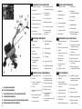 4
4
-
 5
5
-
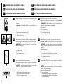 6
6
-
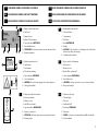 7
7
-
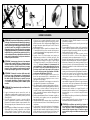 8
8
-
 9
9
-
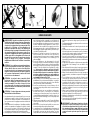 10
10
-
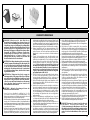 11
11
-
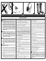 12
12
-
 13
13
-
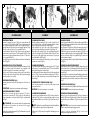 14
14
-
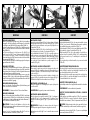 15
15
-
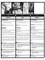 16
16
-
 17
17
-
 18
18
-
 19
19
-
 20
20
-
 21
21
-
 22
22
-
 23
23
-
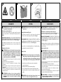 24
24
-
 25
25
-
 26
26
-
 27
27
-
 28
28
-
 29
29
-
 30
30
-
 31
31
-
 32
32
-
 33
33
-
 34
34
-
 35
35
-
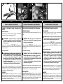 36
36
-
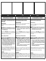 37
37
-
 38
38
-
 39
39
-
 40
40
-
 41
41
-
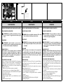 42
42
-
 43
43
-
 44
44
-
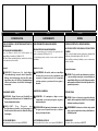 45
45
-
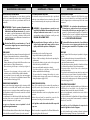 46
46
-
 47
47
-
 48
48
-
 49
49
-
 50
50
-
 51
51
-
 52
52
-
 53
53
-
 54
54
-
 55
55
-
 56
56
-
 57
57
-
 58
58
-
 59
59
-
 60
60


Nibbi MH 198 RKS Bedienungsanleitung
- Typ
- Bedienungsanleitung
- Dieses Handbuch eignet sich auch für
in anderen Sprachen
- français: Nibbi MH 198 RKS Le manuel du propriétaire
- español: Nibbi MH 198 RKS El manual del propietario
- italiano: Nibbi MH 198 RKS Manuale del proprietario
- slovenčina: Nibbi MH 198 RKS Návod na obsluhu

