Groupe Brandt RHD98XE1 Bedienungsanleitung
- Typ
- Bedienungsanleitung

Bedienungsanleitung
Instructions Booklet
Mode d’emploi
Libretto Istruzioni
Gebruiksaanwijzing
Manual de instrucciones
Manual de instruções
Instruktionsbog
NL
IT
FR
GB
DE
ES
PT
DK
Seite wird geladen ...

4DE
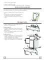
• Die Mitte der Bügellöcher an der Wand markieren.
• Mit einem Bohrer ø 8 mm die markierten Punkte bohren.
• Die Dübel 11 in die Bohrungen einfügen.
• Die Bügel mit den mitgelieferten Schrauben 12a (4,2 x 44,4) fi xieren.
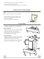
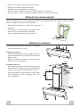
Anschluss in abluftversion
Bei Abluftbetrieb kann die Haube vom Installateur wahlweise mittels Rohr oder Schlauch an die
Außenrohrleitung angeschlossen werden.
• Den Reduzierflansch 9 am Haubenaustritt
an brin gen.
• Das Rohr mit geeigneten Rohrschellen
fi xie ren.
Das hierzu erforderliche Material wird nicht
mitgeliefert.
• Eventuell vorhandene Aktivkohlefilter
ent neh men.
Kaminmontage
• Das Winkelstück 15 am Lüftereil mit 5 der
Lie fe rung beigefügten Schrauben 12d (2,9x9,5)
befestigen.
Oberer Kaminteil
• Die beiden seitlichen Schenkel leicht
aus ein an der bie gen, hinter den Bügeln 7.2.1
ein hän gen und bis zum Anschlag wieder
schließen.
• Bei den Bügeln mit Hilfe der 4 mitgelieferten
Schrauben 12c fi xieren.
Unterer Kaminteil
• Die beiden seitlichen Schenkel des Kaminteils
leicht auseinanderbiegen, zwischen dem obe ren
Kaminteil und der Wand einhängen und bis zum
Anschlag wieder schließen.
• Den unteren Teil seitlich am Haubenkörper mit
2 der mitgelieferten Schrauben 12c fi xieren.
12c
2.1
2.2
2
7.2.1
12c
9

5GB
X
1÷2
7.2.1
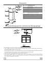
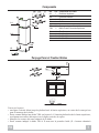
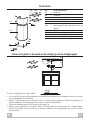
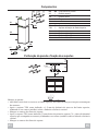
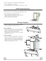
Components
Ref. Q.ty Product Components
2.1 1 Upper Section
2.2 1 Lower Section
9 1 Flange
15 1 Angle iron
Ref. Q.ty Installation Components
7.2.1 2 Upper Chimney Section Fixing Brackets
11 4 Wall Plugs
12a 4 Screws 4,2 x 44,4
12c 6 Screws 2,9 x 6,5
12d 4 Screws 2,9 x 9,5
Wall drilling and bracket fi xing
Wall marking:
• Draw a vertical line on the supporting wall up to the ceiling, or as high as practical, at the centre
of the area in which the hood will be installed.
• Place bracket 7.2.1 on the wall as shown about 1-2 mm from the ceiling or upper limit aligning
the centre (notch) with the vertical reference line.
• Mark the wall at the centres of the holes in the bracket.
• Place bracket 7.2.1 on the wall as shown at X mm below the fi rst bracket (X = height of the upper
chimney section supplied), aligning the centre (notch) with the vertical line.
• Mark the wall at the centres of the holes in the bracket.
12d
2.1
2.2
12c
9
15
12a
7.2.1 11

6GB
9
12c
2.1
2.2
2
7.2.1
12c
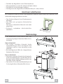
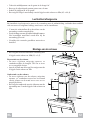
• Drill ø 8 mm holes at all the centre points marked.
• Insert the wall plugs 11 in the holes.
• Fix the brackets using the 12a screws (4,2 x 44,4) supplied.
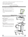
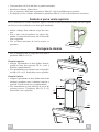
Ducted version air exhaust system
When installing the ducted version, connect the hood to the chimney using either a fl exible or
rigid
pipe, the choice of which is left to the installer.
• Insert the fl ange 9 on the hood body outlet.
• Fix the pipe in position using suffi cient pipe
clamps (not supplied).
• Remove any activated charcoal fi lters.
Flue assembly
• Fasten the angle iron 15 to the hood canopy
using the screws 12d (2.9 x 9.5) provided.
Upper exhaust fl ue
• Slightly widen the two sides of the upper fl ue
and hook them behind the brackets 7.2.1,
making sure that they are well seated.
• Secure the sides to the brackets using the 4
screws 12c (2,9 x 9,5) supplied.
Lower exhaust fl ue
• Slightly widen the two sides of the fl ue and
hook them between the upper fl ue and the wall,
making sure that they are well seated.
• Fix the lower part laterally to the hood body
using the 2 screws 12c (2,9 x 9,5) supplied.
Seite wird geladen ...
Seite wird geladen ...
Seite wird geladen ...
Seite wird geladen ...
Seite wird geladen ...
Seite wird geladen ...
Seite wird geladen ...
Seite wird geladen ...
Seite wird geladen ...
Seite wird geladen ...
Seite wird geladen ...

18DK
9
12c
2.1
2.2
2
7.2.1
12c
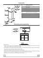
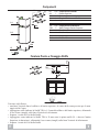
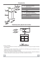
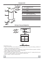
• Bor ø 8 mm huller i alle markerede midterpunkter.
• Insæt vægudtagene 11 i hullerne.
• Fastgør støtterne med de vedlagte 12a skruer (4,2 × 44,4).
Rørført udsugningssystem
Når den rørførte version installeres, skal emhætten tilsluttes afskærmningen ved brug af enten en
fl eksibel eller stiv kanal, alt afhængig af installørens valg.
• Insæt fl angen 9 på emhættens aftræk.
• Fastgør kanalen med brug af tilstrækkelig
mange rørbærere (følger ikke med).
• Fjern eventuelle aktive kulfi ltre.
Montage af røgkanal
• Fastgør vinkeljernet 15 til emhættens baldakin
med de vedlagte skruer 12d (2.9 x 9.5).
Øverste røgkanal
• Udvid de to sider på den øverste røgkanal en
smule og hægt dem bag ved støtterne 7.2.1.
Efterprøv at de sidder godt på plads.
• Fastgør siderne til støtterne med de 4 vedlagte
skruer 12c (2,9 x 9,5).
Nederste røgkanal
• Udvid de to sider på røgkanalen en smule og
hægt dem mellem den øverste røgkanal og
væggen. Efterprøv at de sidder godt på plads.
• Fastgør den nederste del sidelæns til emhætten
med de to skruer 12c (2,9 x 9,5).
-
 1
1
-
 2
2
-
 3
3
-
 4
4
-
 5
5
-
 6
6
-
 7
7
-
 8
8
-
 9
9
-
 10
10
-
 11
11
-
 12
12
-
 13
13
-
 14
14
-
 15
15
-
 16
16
-
 17
17


Groupe Brandt RHD98XE1 Bedienungsanleitung
- Typ
- Bedienungsanleitung
in anderen Sprachen
- English: Groupe Brandt RHD98XE1 Owner's manual
- français: Groupe Brandt RHD98XE1 Le manuel du propriétaire
- español: Groupe Brandt RHD98XE1 El manual del propietario
- italiano: Groupe Brandt RHD98XE1 Manuale del proprietario
- Nederlands: Groupe Brandt RHD98XE1 de handleiding
- português: Groupe Brandt RHD98XE1 Manual do proprietário
- dansk: Groupe Brandt RHD98XE1 Brugervejledning