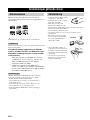
Yamaha MCR-E410 Bedienungsanleitung
- Kategorie
- CD-Spieler
- Typ
- Bedienungsanleitung
Dieses Handbuch ist auch geeignet für

YAMAHA ELECTRONICS CORPORATION, USA
6660 ORANGETHORPE AVE., BUENA PARK, CALIF. 90620, U.S.A.
YAMAHA CANADA MUSIC LTD.
135 MILNER AVE., SCARBOROUGH, ONTARIO M1S 3R1, CANADA
YAMAHA ELECTRONIK EUROPA G.m.b.H.
SIEMENSSTR. 22-34, 25462 RELLINGEN BEI HAMBURG, GERMANY
YAMAHA ELECTRONIQUE FRANCE S.A.
RUE AMBROISE CROIZAT BP70 CROISSY-BEAUBOURG 77312 MARNE-LA-VALLEE CEDEX02, FRANCE
YAMAHA ELECTRONICS (UK) LTD.
YAMAHA HOUSE, 200 RICKMANSWORTH ROAD WATFORD, HERTS WD18 7GQ, ENGLAND
YAMAHA SCANDINAVIA A.B.
J A WETTERGRENS GATA 1, BOX 30053, 400 43 VÄSTRA FRÖLUNDA, SWEDEN
YAMAHA MUSIC AUSTRALIA PTY, LTD.
17-33 MARKET ST., SOUTH MELBOURNE, 3205 VIC., AUSTRALIA
©
2006 All rights reserved.
OWNER'S MANUAL
MODE D'EMPLOI
BEDIENUNGSANLEITUNG
BRUKSANVISNING
MANUALE DI ISTRUZIONI
MANUAL DE INSTRUCCIONES
GEBRUIKSAANWIJZING
G
AMPLI-TUNER/LECTEUR CD
RECEIVER/CD PLAYER
Printed in China WH45500
MCR-E410_GB_cv.fm Page 1 Tuesday, June 20, 2006 6:12 PM

i
DK
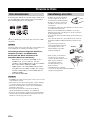
Advarsel:
Laserrudstråling ved åbning når sikkerhesafbrydere er ude
af funktion. Undgå u tsættelse for stråling.
Bemærk:
Netafbryderen STANDBY/ON er sekundært indkoblet og
afbryder ikke strømmen fra nette. Den indbyggede netdel
er derfor tilsluttet til lysnettet så længe netstikket sidder i
stikkontakten.
N
Observer:
Nettbryteren STANDBY/ON er sekundert innkoplet. Den
innebygdenetdelen er derfor ikke frakoplet nettet så lenge
apparatet er tilsluttet nettkontakten.
S
Klass 1 laserapparat
Varning!
Om apparaten används på annat sätt än i denna
bruksanvisning specificerats, kann användaren utsättas för
laserstrålning, som översjruder gränsen för läserklass 1.
Observera!
Strömbrytaren STANDBY/ON är sekundärt kopplad och inte
bryter strömmen fråan nätet Den inbyggda nätdelen är
därför ansluten till elnätet så länge stickproppen sitter i v
ägguttaget.
SF
Luokan 1 laserlaite + Klass 1 laserapparat
Varoitus!
Laitteen käyttäminen muulla kuin tässä käyttöohjeessa
mainitulla tavalla saattaa altistaa käyttäjän
turvallisuusluokan 1 ylittävälle lasersäleilille.
Huom.
Toiminnanvalitsin STANDBY/ON on kytketty toisiopuolelle,
eikä se kytke laitetta irti sähköverkosta. Sisäänrakennettu
verkko-osa on kytkettynä sähköverkkoon aina silloin, kun
pistoke on pistorasiassa.
CAUTION INVISIBLE LASER RADIATION WHEN OPEN
AND INTERLOCKS DEFEATED. AVOID EXPOSURE TO
BEAM.
VORSICHT! UNSICHTBARE LASERSTRAHLUNG TRITT
AUS, WENN DECKEL GEÖFFNET UND WENN
SICHERHEITSVERRIEGELUNG ÜBERBRÜCKT IST.
NICHT DEM STRAHL AUSSETSEN!
VARNING OSYNLIG LASERSTRÅLNING NÄR DENNA
DEL ÄR ÖPPNAD OCH SPÄRR ÄR URKOPPLAD.
STRÅLEN ÄR FARLIG.
ADVARSEL USYNLIG LASERSTRÅLING VED ÅBNING,
NÅR SIKKERHEDSAFBRYDERE ER UDE AF FUNKTION.
UNDGÅ UDSÆTTELSE FOR STRÅLING.
VAROITUS! SUOJAKOTEL OA EI SAA AVATA. LAITE
SISÄLTÄÄ LASERDIODIN, JOKA LÄHETTÄÄ
(NÄKYMÄTÖNTÄ) SILMILLE VAARALLISTA LASER
SÄTEILYÄ.
ADVARSEL USYNLIG LASERBESTRÅLING NÅR DENNE
DELEN ER ÅPEN OG SIKKERHETSSPERREN ER
UTKOBLET. UNNGÅ UTSETTELSE FOR STRÅLING.
CLASS 1 LASER PRODUCT
LASER KLASSE 1 PRODUKT
LUOKAN 1 LASERLAITE
KLASS 1 LASER APPARAT
PRODUIT LASER DE CLASSE 1
VARO!
AVATTAESSA JA SUOJALUKITUS OHITETTAESSA
OLET ALTTIINA NÄKYMÄTTÖMÄLLE
LASERSÄTEILYLLE. ÄLÄ KATSO SÄTEESEEN.
VARNING!
OSYNLIG LASERSTRÅLNING NÄR DENNA DEL ÄR
ÖPPNAD OCH SPÄRREN ÄR URKOPPLAD.
BETRAKTA EJ STRÅLEN.

ii
1 To assure the finest performance, please read this manual
carefully. Keep it in a safe place for future reference.
2 Install this unit (RX-E410 and CDX-E410) in a well ventilated,
cool, dry, clean place with at least 10 cm on the top (except for
CDX-E410), 10 cm on the left and right, and 10 cm at the back of
this unit — away from direct sunlight, heat sources, vibration,
dust, moisture, and/or cold.
3 Locate this unit away from other electrical appliances, motors, or
transformers to avoid humming sounds.
4 Do not expose this unit to sudden temperature changes from cold
to hot, and do not locate this unit in an environment with high
humidity (i.e. a room with a humidifier) to prevent condensation
inside this unit, which may cause an electrical shock, fire,
damage to this unit, and/or personal injury.
5 Avoid installing this unit where foreign object may fall onto this
unit and/or this unit may be exposed to liquid dripping or
splashing. On the top of this unit, do not place:
– Other components, as they may cause damage and/or
discoloration on the surface of this unit.
– Burning objects (i.e. candles), as they may cause fire, damage
to this unit, and/or personal injury.
– Containers with liquid in them, as they may fall and liquid
may cause electrical shock to the user and/or damage to this
unit.
6 Do not cover this unit with a newspaper, tablecloth, curtain, etc.
in order not to obstruct heat radiation. If the temperature inside
this unit rises, it may cause fire, damage to this unit, and/or
personal injury.
7 Do not plug in this unit to a wall outlet until all connections are
complete.
8 Do not operate this unit upside-down. It may overheat, possibly
causing damage.
9 Do not use force on switches, knobs and/or cords.
10 When disconnecting the power cable from the wall outlet, grasp
the plug; do not pull the cable.
11 Do not clean this unit with chemical solvents; this might damage
the finish. Use a clean, dry cloth.
12 Only voltage specified on this unit must be used. Using this unit
with a higher voltage than specified is dangerous and may cause
fire, damage to this unit, and/or personal injury. YAMAHA will
not be held responsible for any damage resulting from use of this
unit with a voltage other than specified.
13 Do not attempt to modify or fix this unit. Contact qualified
YAMAHA service personnel when any service is needed.
The cabinet should never be opened for any reasons.
14 When not planning to use this unit for long periods of time (i.e.
vacation), disconnect the AC power plug from the wall outlet.
15 Be sure to read the “Troubleshooting” section on common
operating errors before concluding that this unit is faulty.
16 Before moving this unit, press STANDBY/ON to set this unit in
standby mode, and disconnect the AC power plug from the wall
outlet.
17 Condensation will form when the surrounding temperature
changes suddenly. Disconnect the power cable from the outlet,
then leave the unit alone.
18 When using the unit for a long time, the unit may become warm.
Turn the power off, then leave the unit alone for cooling.
19 Install this unit near the wall outlet and where the AC power plug
can be reached easily.
DANGER
When this unit is plugged to the wall outlet, do not place your
eyes close to the opening of the disc tray and other openings to
look into inside.
■ For U.K. customers
If the socket outlets in the home are not suitable for the plug
supplied with this appliance, it should be cut off and an
appropriate 3 pin plug fitted. For details, refer to the instructions
described below.
The plug severed from the mains lead must be destroyed, as a
plug with bared flexible cord is hazardous if engaged in a live
socket outlet.
■ Special Instructions for U.K. Model
CAUTION: READ THIS BEFORE OPERATING YOUR UNIT.
This unit is not disconnected from the AC power source as
long as it is connected to the wall outlet, even if this unit itself
is turned off. This state is called the standby mode. In this
state, this unit is designed to consume a very small quantity of
power.
CAUTION
Use of controls or adjustments or performance of procedures
other than those specified herein may result in hazardous
radiation exposure.
The laser component in this product is capable of emitting
radiation exceeding the limit for Class 1.
WARNING
TO REDUCE THE RISK OF FIRE OR ELECTRIC SHOCK,
DO NOT EXPOSE THIS APPLIANCE TO RAIN OR
MOISTURE.
Note
IMPORTANT
THE WIRES IN MAINS LEAD ARE COLOURED IN
ACCORDANCE WITH THE FOLLOWING CODE:
Blue: NEUTRAL
Brown: LIVE
As the colours of the wires in the mains lead of this appa-
ratus may not correspond with the coloured markings
identifying the terminals in your plug, proceed as follows:
The wire which is coloured BLUE must be connected to
the terminal which is marked with the letter N or coloured
BLACK. The wire which is coloured BROWN must be
connected to the terminal which is marked with the letter L
or coloured RED.
Making sure that neither core is connected to the earth
terminal of the three pin plug.

1 En
English
PREPARATIONINTRODUCTION
TUNER
OPERATIONS
OTHER
OPERATIONS
ADDITIONAL
INFORMATION
BASIC
OPERATIONS
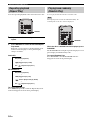
Features .................................................................. 2
Supplied Accessories ............................................. 2
Controls and Functions......................................... 3
Receiver (RX-E410) .................................................. 3
CD player (CDX-E410)............................................. 6
Remote control........................................................... 8
Connecting the System ........................................ 12
Connecting Antennas .......................................... 14
Connecting the AM loop antenna ............................ 14
Connecting the FM antenna..................................... 14
Connecting External Components ..................... 15
Connecting an MD player or a tape deck ................ 15
Connecting an MD recorder or a CD recorder ........ 15
Connecting a YAMAHA iPod universal dock ........ 16
Connecting the Power Cables............................. 17
Adjusting the Clock............................................. 18
Basic Receiver Operations.................................. 19
Changing the front panel display settings................ 20
Basic Disc Playback Operations......................... 21
Switching the playback information display ........... 22
Repeating playback
(Repeat Play) ....................................................... 24
Playing back randomly
(Random Play)..................................................... 24
Customizing playback order (Program Play) .......... 25
FM/AM Tuning.................................................... 26
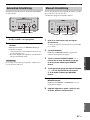
Automatic tuning ..................................................... 26
Manual tuning.......................................................... 26
Automatic preset tuning........................................... 27
Manual preset tuning ............................................... 27
Selecting preset stations........................................... 28
Radio Data System Tuning (U.K. and Europe
Models Only).................................................... 29
Selecting the Radio Data System program .............. 29
Displaying the Radio Data System information ...... 30
Setting the Timer.................................................. 32
Setting the clock timer............................................. 32
Setting the sleep timer ............................................. 33
Setting the auto-standby mode............................ 34
Controlling iPod ................................................... 35
Available iPod operations........................................ 35
Using iPod ............................................................... 36
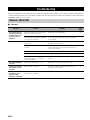
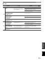
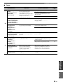
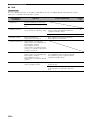
Troubleshooting.................................................... 38
Receiver (RX-E410) ................................................ 38
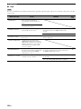
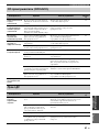
CD player (CDX-E410)........................................... 41
Remote control ........................................................ 41
Notes on Discs ....................................................... 42
Disc information ...................................................... 42
Handling a disc ........................................................ 42
Glossary................................................................. 43
Audio information ................................................... 43
Copyright and logo marks ....................................... 43
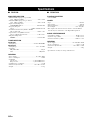
Specifications ........................................................ 44
Contents
INTRODUCTION
PREPARATION
BASIC OPERATIONS
TUNER OPERATIONS
OTHER OPERATIONS
ADDITIONAL INFORMATION

FEATURES
2 En
Receiver (RX-E410)
• Maximum RMS output power per channel
65W + 65W (1% THD, 1 kHz, 6Ω)
• 40-station FM/AM preset tuning
• iPod dock terminal
• Pure Direct mode
CD player (CDX-E410)
• Plays Audio CDs, MP3 CDs, and WMA CDs.
• CD Text data display
• Optical and coaxial digital output jacks
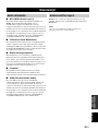
■ About this manual
• In this manual, “RX-E410” is described as “receiver” and “CDX-E410” is described as “CD player”.
• This manual describes how to operate the system using a remote control except when it is not available. Some of these operations are
also available using the front panel buttons.
• y indicates a tip for your operation.
• Notes contain important information about safety and operating instructions.
• This manual is printed prior to production. Design and specifications are subject to change in part as a result of improvements, etc. In
case of differences between the manual and the product, the product has priority.
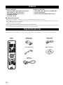
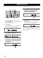
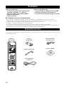
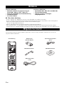
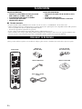
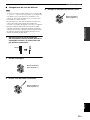
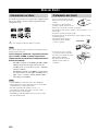
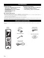
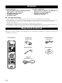
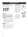
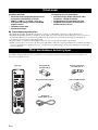
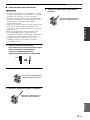
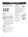
This product includes the following accessories. Before connecting this system, make sure you received all of the following parts.
Features
Supplied Accessories
STANDBY/ON
1234
56
90
78
DIMMER
REPEATPROG
FREQ/TEXT
TIME/INFO
PTY SEEK
MODE START
RANDOM
MENU
FOLDER/PRESET
ENTER
FILE
/A-E
FILE
/A-E
DISPLAY
SLEEP
CD TUNER BAND
TAPE/MD AUX/TV DOCK
INPUT VOLUME
Indoor FM antenna
System control
cable (0.6 m)
AM loop antenna
Batteries (x2)
(AA, R06, UM-3)
Remote
control
Audio pin
cable (1.5 m)

3 En
English
INTRODUCTION
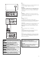
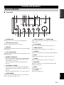
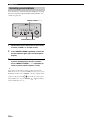
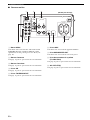
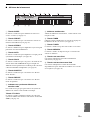
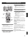
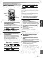
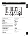
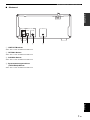
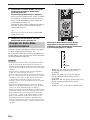
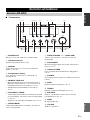
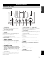
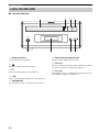
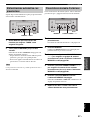
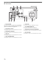
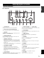
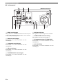
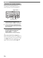
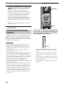
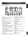
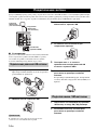
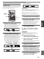
■ Front panel
1 STANDBY/ON
Turns the receiver on or sets it to the standby mode.
2 Remote control sensor
Receives signals from the remote control.
3 DISPLAY
Switches the information shown in the front panel display
(see page 20).
4 Front panel display
Shows the various infomaiton such as the clock time or the
tuning frequency.
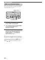
5 MEMORY (TIME ADJ)
• Stores a preset station in the memory. Hold down this
key for more than 2 seconds to preset radio stations
automatically (see page 27).
• Sets the clock before using the timer function (see
page 18).
6 AUTO/MAN’L (TIMER)
• Switches between Automatic Tuning mode and Manual
Tuning mode when tuner is selected as an input source (see
page 26).
• Turns the clock timer function on or off (see page 32).
7 PRESET/BAND
Switches between FM, AM, and the preset mode when
tuner is selected as an input source.
8 PRESET/TUNING d / u (HOUR, MIN)
Selects a tuning frequency when tuner is selected as an
input source.
9 PURE DIRECT
Turns on or off the Pure Direct mode (see page 19).
0 TIMER indicator
Lights up when the clock timer is on (see page 32).
A PHONES
Outputs audio signals for private listening with headphones.
B BASS
Adjusts the low frequency responce (see page 19).
C TREBLE
Adjusts the high frequency responce (see page 19).
D BALANCE
Adjusts the volume level of each left and right speaker
channel (see page 19).
E INPUT
Selects an input source.
F VOLUME
Adjusts the volume level.
Controls and Functions
Receiver (RX-E410)
MIN MAX
VOLUME
INPUT
BALANCE
LR
TREBLEBASS
PHONES
STANDBY/ON
TIMER
DISPLAY MEMORY
NATURAL SOUND STEREO RECEIVER RX-E410
PRESET/BAND
PRESET/TUNING
PURE DIRECT
HOURTIMER
TIME ADJ
MIN
AUTO/MAN'L
12 345 6 7 8 9
A0BCDE F

4 En
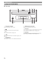
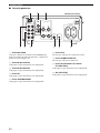
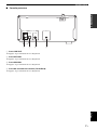
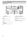
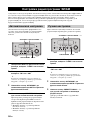
Controls and Functions
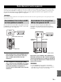
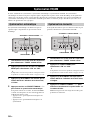
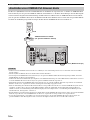
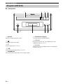
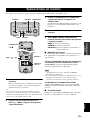
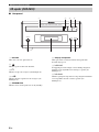
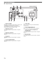
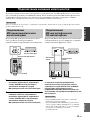
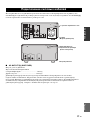
■ Rear panel
1 DOCK terminal
Use to connect a YAMAHA iPod universal dock (such as
YDS-10 sold separately) where your iPod can be stationed
(see page 16).
2 Antenna terminals
See page 14 for connection information.
3 Speaker terminals
See page 13 for connection information.
4 CD jacks
See page 12 for connection information.
5 TAPE/MD IN/OUT jacks
See page 15 for connection information.
6 AUX jacks
Use to connect the external components.
7 SUBWOOFER OUT jack
Use to connect the subwoofer.
8 System connector (TO CDX-E410) jack
See page 12 for connection information.
9 AC OUTLET(S)
See page 17 for connection information.
LR
LR
AC OUTLETS
SWITCHED
MAINS
SPEAKERS
DOCK
CD
TAPE/MD
AUX
OUT
IN
FM
GND
AM
ANTENNA
6
MIN / SPEAKER
TO CDX-E410
SUBWOOFER
OUT
100W MAX. TOTAL
75
UNBAL.
12 3
64
578 9
(Europe model)

5 En
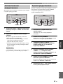
Controls and Functions
English
INTRODUCTION
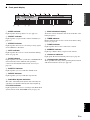
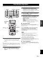
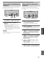
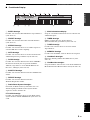
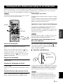
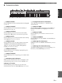
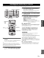
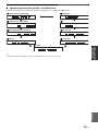
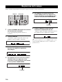
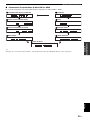
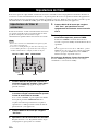
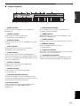
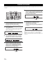
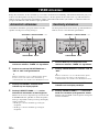
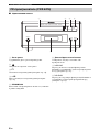
■ Front panel display
1 SLEEP indicator
Lights up when the sleep timer is on (see page 33).
2 PRESET indicator
Lights up when you preset radio stations manually (see
page 27).
3 STEREO indicator
Lights up when the receiver is receiving a strong signal
from an FM stereo broadcast.
4 AUTO indicator
Lights up when the receiver is in the Automatic Tuning
mode (see page 26).
5 DOCK indicator
Lights up when you station your iPod in a YAMAHA iPod
universal dock (such as YDS-10 sold separately)
connected to the DOCK terminal of the receiver (see
page 16).
6 SHUFFLE indicator
Lights up when you set your iPod in shuffle mode.
7 REPEAT indicator
Lights up when you set your iPod in repeat mode.
8 Radio Data System indicators
The name of the Radio Data System data offered by the
currently received Radio Data System station lights up.
PTY HOLD indicator
Lights up when the receiver is seaching for the Radio Data
System stations in the PTY SEEK mode (see page 29).
9 Multi-information display
Shows the various infomaiton such as the clock time or the
tuning frequency.
0 TIMER indicator
Flashes when the the receiver is in the clock timer setting
mode (see page 32).
A TUNED indicator
Lights up when the receiver is tuned into a station.
B MEMORY indicator
Lights up or flashes when you preset radio stations.
C iPod menu indicators
Light up the iPod menu currently selected (see page 36).
D iPod operation indicators
Show operable cursor keys when operating the iPod menu
with the menu browse mode (see page 36).
GENRES
SONGS
ALBUMS
ARTISTSPLAYLISTS
MEMORY
TUNED
TIMER
SLEEP
STEREO
AUTO
DOCK
SHUFFLE
REPEAT
PS
PTY RT CT PTY
HOLD
PRESET
1 234567 8
0AB C
D
9

6 En
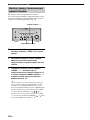
Controls and Functions
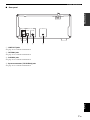
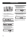
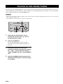
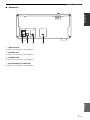
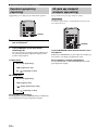
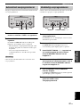
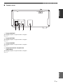
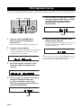
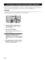
■ Front panel
1 Disc tray
Holds a disc to be played back.
2
Opens and closes the disc tray.
3 s
Stops playback (see page 21).
4 h/e
Starts or pauses playback (see page 21).
5 STANDBY/ON
Turns the CD player on or sets it to the standby mode.
6 Front panel display
Shows the current status of the CD player.
7 b/w
Skips to the begining of the current track. Press and hold
to fast reverse (see page 21).
8 f/a
Skips to the next track. Press and hold to fast forward (see
page 21).
CD player (CDX-E410)
STANDBY/ON
NATURAL SOUND COMPACT DISC PLAYER CDX-E410
5
1234
678

7 En
Controls and Functions
English
INTRODUCTION
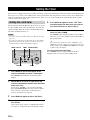
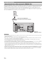
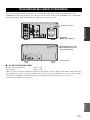
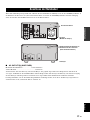
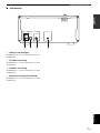
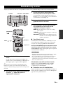
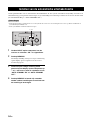
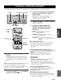
■ Rear panel
1 LINE OUT jacks
See page 12 for connection information.
2 OPTICAL jack
See page 15 for connection information.
3 COAXIAL jack
See page 15 for connection information.
4 System connector (TO RX-E410) jack
See page 12 for connection information.
L
R
LINE OUT
OPTICAL COAXIAL
DIGITAL OUT TO RX-E410
MAINS
12 43

8 En
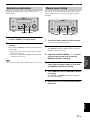
Controls and Functions
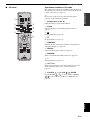
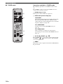
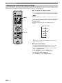
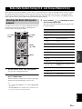
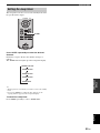
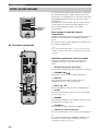
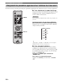
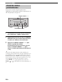
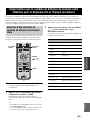
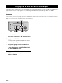
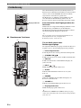
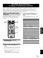
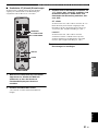
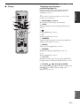
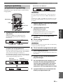
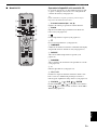
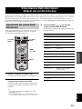
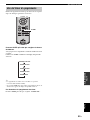
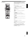
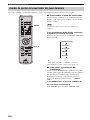
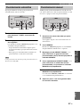
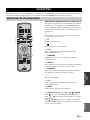
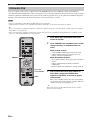
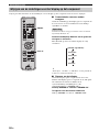
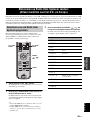
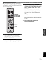
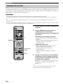
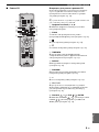
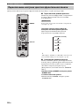
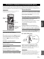
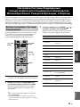
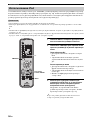
■ Common functions
This remote control can operate the PianoCraft system
components (including tuner functions) and an iPod
stationed in a YAMAHA iPod universal dock connected to
the receiver.
To operate the CD player, tuner functions, or an iPod
using the remote control, you need to set the receiver to
the corresponding input mode.
To switch the input mode of the receiver
Press the corresponding input selection key on the remote
control (or INPUT on the front panel).
The name of the corresponding input source appears in the
front panel display of the receiver.
y
For a complete list of the remote control functions used to control
your iPod, refer to “Available iPod operations” (see page 35).
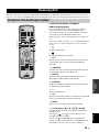
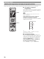
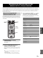
Operations common to all modes
The following operations are available for the receiver
when it is set to any input mode.
1 Infrared signal transmitter
Sends signals to the component you want to control.
2 STANDBY/ON ( )
Turns the receiver on or sets it to the standby mode.
3 DISPLAY
Switches the information shown in the front panel display
(see page 20).
4 INPUT /
Selects the input source on the receiver.
5 SLEEP
Sets the sleep timer on the receiver (see page 33).
6 DIMMER
Changes the brightness of the receiver’s front panel
display (see page 20).
7 VOLUME +/–
Adjusts the overall volume level on the receiver.
8 Input selection keys
Select the input source on the receiver.
y
STANDBY/ON, DIMMER and SLEEP operations also control
the CD player by the system control connection (see page 12).
Remote control
DISPLAY
SLEEP
CD TUNER BAND
TAPE/MD AUX/TV DOCK
INPUT VOLUME
Input
selection
keys
STANDBY/ON
1234
56
90
78
DIMMER
REPEATPROG
FREQ/TEXT
TIME/INFO
PTY SEEK
MODE START
RANDOM
MENU
FOLDER/PRESET
ENTER
FILE
/A-E
FILE
/A-E
DISPLAY
SLEEP
CD TUNER BAND
TAPE/MD AUX/TV DOCK
INPUT VOLUME
STANDBY/ON
1234
56
90
78
DIMMER
REPEATPROG
FREQ/TEXT
TIME/INFO
PTY SEEK
MODE START
RANDOM
MENU
FOLDER/PRESET
ENTER
FILE
/A-E
FILE
/A-E
DISPLAY
SLEEP
CD TUNER BAND
TAPE/MD AUX/TV DOCK
INPUT VOLUME
1
2
3
4
5
6
7
8

9 En
Controls and Functions
English
INTRODUCTION
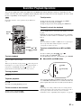
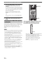
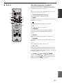
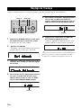
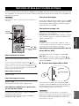
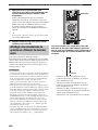
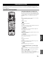
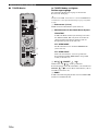
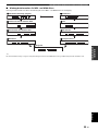
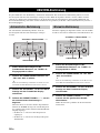
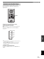
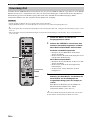
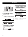
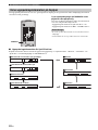
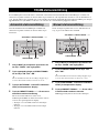
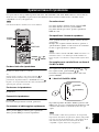
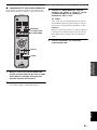
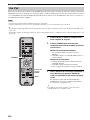
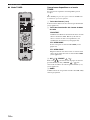
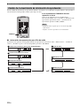
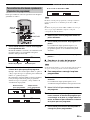
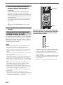
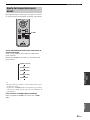
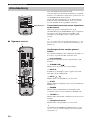
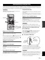
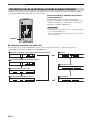
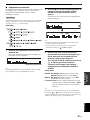
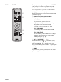
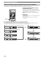
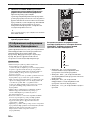
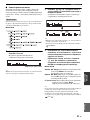
■ CD mode Operations available in CD mode
The following operations are available for the CD player if
the CD player is connected to the receiver with the system
control connection (see page 12).
y
Press CD to set the receiver to the CD mode before
carrying out the following operations.
1 Number keys (1 to 9, 0)
Input numerals to specify track numbers.
2 PROG
Sets the CD player to the track program mode (see
page 25).
3 e
Pauses playback (see page 21).
4 s
Stops playback (see page 21).
5 TIME/INFO
Switches the disc information shown in the CD player’s
front panel display (see page 22).
6 REPEAT
Selects the Repeat Play mode (see page 24).
7 RANDOM
Turns on/off the Random Play feature (see page 24).
8 h
Starts playback (see page 21).
9 b, a
Skips to the beginning of the current track or next track.
Press and hold to fast reverse or fast forward (see
page 21).
0 FOLDER / , FILE / , ENTER
Press FOLDER / to select a folder and FILE
/ to select a file for an MP3 or a WMA disc (see
page 21).
STANDBY/ON
1234
56
90
78
DIMMER
REPEATPROG
FREQ/TEXT
TIME/INFO
PTY SEEK
MODE START
RANDOM
MENU
FOLDER/PRESET
ENTER
FILE
/A-E
FILE
/A-E
DISPLAY
SLEEP
CD TUNER BAND
TAPE/MD AUX/TV DOCK
INPUT VOLUME
9
62
3
4
5
1
7
8
0

10 En
Controls and Functions
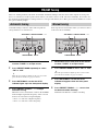
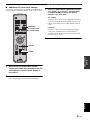
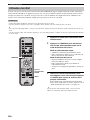
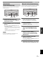
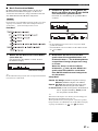
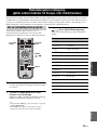
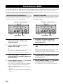
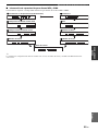
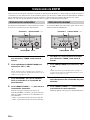
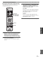
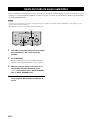
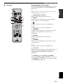
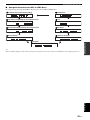
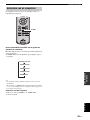
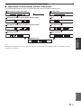
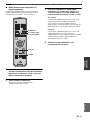
■ TUNER mode Operations available in TUNER mode
The following operations are available for the receiver.
y
Press TUNER to set the receiver to the TUNER mode before
carrying out the following operations.
1 Number keys (1 to 8)
Selects preset station number (see page 28).
2 Radio Data System tuning keys
FREQ/TEXT
Switches the Radio Data System display between the
PS mode, PTY mode, RT mode, CT mode (if the
station offers the corresponding data services) and the
frequency display (see page 30).
PTY SEEK MODE
Sets the receiver to the PTY SEEK mode (see
page 29).
PTY SEEK START
Starts searching for a station once the desired
program type is selected in the PTY SEEK mode (see
page 29).
3 A-E / , PRESET /
Press A-E / to select a preset station group (A to E)
and PRESET / to select a preset station number
(1 to 8) (see page 28).
4 BAND
Switches the radio reception mode between FM, AM and
the preset mode.
STANDBY/ON
1234
56
90
78
DIMMER
REPEATPROG
FREQ/TEXT
TIME/INFO
PTY SEEK
MODE START
RANDOM
MENU
FOLDER/PRESET
ENTER
FILE
/A-E
FILE
/A-E
DISPLAY
SLEEP
CD TUNER BAND
TAPE/MD AUX/TV DOCK
INPUT VOLUME
1
2
3
4

11 En
Controls and Functions
English
INTRODUCTION
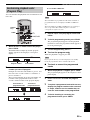
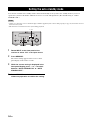
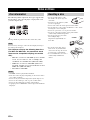
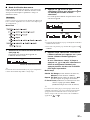
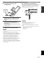
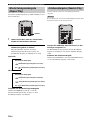
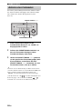
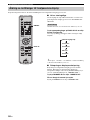
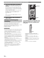
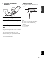
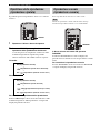
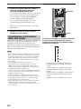
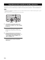
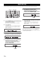
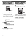
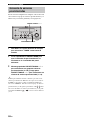
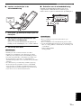
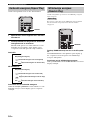
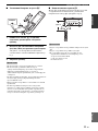
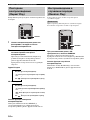
■ Installing the batteries in the remote
control
1 Press the mark on the battery cover and
open the cover.
2 Insert the two supplied batteries (AA, R06,
UM-3) into the battery compartment.
Make sure you insert the batteries according to the
polarity markings (+ and –).
3 Close the battery cover.
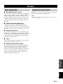
• Do not use an old battery together with new one.
• Do not use different types of batteries (for example, alkaline
and manganese) together. Each type of battery has its own
characteristics even if they are similar in shape.
• If the batteries run out, immediately remove them from the
remote control to prevent an explosion or acid leak.
• Dispose of the batteries according to the regional regulations.
• If a battery starts leaking, dispose of it immediately. Be careful
not to let leaking battery acid come into contact with your skin
or clothing. Before inserting new batteries, wipe the
compartment clean.
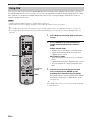
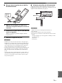
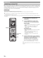
■ Using the remote control
Use the remote control within 6 m (20 feet) of the
component you want to control and point it toward its
remote control sensor (see page 3).
• Be careful not to spill liquid on the remote control.
• Be careful not to drop the remote control.
• Do not leave the remote control in the following places:
– hot or humid places, such as near a heater or in a bathroom
– extremely cold places
– dusty places
Notes
Press
Notes
MIN MAX
VOLUME
INPUT
BALANCE
LR
TREBLEBASS
PHONES
STANDBY/ON
TIMER
DISPLAY MEMORY
NATURAL SOUND STEREO RECEIVER RX-E410
PRESET/BAND
PRESET/TUNING
PURE DIRECT
HOURTIMER
TIME ADJ
MIN
AUTO/MAN'L
30˚ 30˚
Within 6 m
(20 feet)

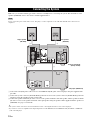
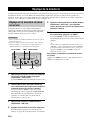
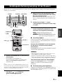
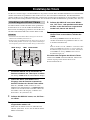
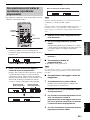
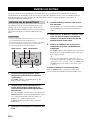
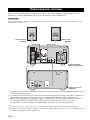
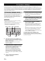
CONNECTING THE SYSTEM
12 En
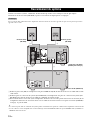
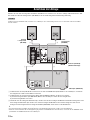
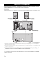
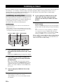
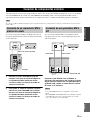
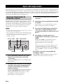
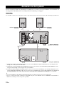
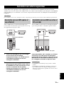
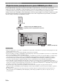
Make sure you read the following procedure and notes carefully before connecting the system. For information on the
speakers (NX-E800), refer to the owner’s manual supplied with it.
Do not connect the power cable of the receiver, CD player, or other components to the wall outlet until all cable connections are
completed.
1 Connect the CD (L/R) jacks of the receiver to the LINE OUT (L/R) jacks of the CD player using the supplied audio
pin cable.
2 Connect the system connector (TO CDX-E410) jack of the receiver to the system connector (TO RX-E410) jack of the
CD player using the supplied system control cable.
3 Connect the speaker terminals (L) of the receiver to the speaker terminals of the left speaker and the speaker terminals
(R) of the receiver to the speaker terminals of the right speaker using the speaker cables supplied with the speaker set
(NX-E800). See page 13 for details.
y
• The system control connection is used to transmit the remote control signals from the receiver to the CD player.
• If you want to connect an amplifier with a digital input instead of the RX-E410, use the DIGITAL OUT (COAXIAL or OPTICAL)
jacks of the CD player.
Connecting the System
Note
LR
LR
MAINS
SPEAKERS
DOCK
CD
TAPE/MD
AUX
OUT
IN
FM
GND
AM
ANTENNA
75
UNBAL.
TO CDX-E410
SUBWOOFER
OUT
100W MAX. TOTAL
AC OUTLETS
SWITCHED
6
MIN / SPEAKER
L
R
LINE OUT
OPTICAL COAXIAL
DIGITAL OUT TO RX-E410
MAINS
1
3
3
2
Receiver (RX-E410)
(Europe model)
CD player (CDX-E410)
Left speaker
(NX-E800)
Right speaker
(NX-E800)

Connecting the System
13 En
English
PREPARATION
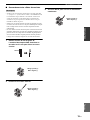
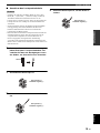
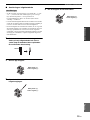
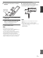
■ Connecting the speaker cable
• Be sure to connect the left channel (L), right channel (R), “+”
(red) and “–” (black) properly. If the connections are faulty, no
sound will be heard from the speakers, and if the polarity of the
speaker connections is incorrect, the sound will be unnatural
and lack bass.
• Do not let the bare speaker wires touch each other or do not let
them touch any metal part of the receiver. This could damage
the receiver and/or the speakers.
• When connecting another speaker set instead of the NX-E800,
be sure to use speakers with the specified impedance shown on
the rear panel of the receiver and magnetically shielded. In case
the magnetically shielded speakers interfere with the monitor,
place the speakers away from the monitor.
1 Remove approximately 10 mm (3/8 in) of
insulation from the end of each speaker
cable and then twist the exposed wires of the
cable together to prevent short circuits.
2 Unscrew the knob.
3 Insert the bare wire into the terminal.
4 Tighten the knob to secure the wire.
Notes
10 mm (3/8 in)
Red: positive (+)
Black: negative (–)
Red: positive (+)
Black: negative (–)
Red: positive (+)
Black: negative (–)

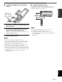
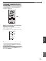
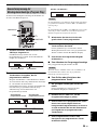
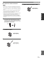
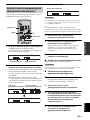
CONNECTING ANTENNAS
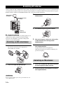
14 En
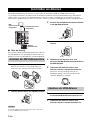
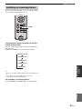
To enjoy radio on the receiver, connect the supplied AM and FM antennas to the designated terminals. If there is a
problem of weak radio wave reception in your area or you want to improve radio reception, we recommend that you use
optional outdoor antennas. For details, consult the nearest authorized YAMAHA dealer or service center.
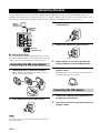
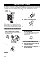
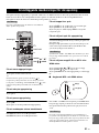
■ About grounding
For maximum safety and minimum interference, connect
the antenna GND terminal to a good earth ground. A good
earth ground is a metal stake driven into moist earth.
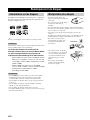
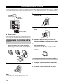
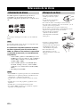
1 Attach the antenna stand to the antenna.
When attaching the antenna to the wall, you do not
need to use the antenna stand.
2 Press down the tab of the AM terminal.
Depending on the product, the shape of the tab is different from
the described illust.
3 Insert the AM loop antenna lead wires into
the AM terminal.
4 Replace the tab back to secure the wire.
5 Repeat steps 2 to 4 to insert the AM loop
antenna lead wires into the GND terminal.
6 Place the antenna away from the receiver and
speaker cables.
While listening to the radio, rotate the antenna head
to find the best angle for reception.
1 Connect the supplied indoor FM antenna to
the FM jack of the receiver.
2 Place the antenna away from the receiver and
speaker cables.
Connecting Antennas
Connecting the AM loop antenna
Note
LR
LR
SPEAKERS
DOCK
CD
TAPE/MD
AUX
OUT
IN
FM
GND
AM
ANTENNA
75
UNBAL.
6
MIN / SPEAKER
Indoor FM
antenna
(supplied)
AM loop
antenna
(supplied)
Ground
(GND terminal)
Connecting the FM antenna

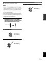
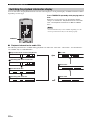
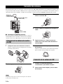
CONNECTING EXTERNAL COMPONENTS
15 En
English
PREPARATION
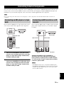
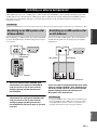
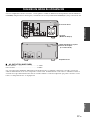
You can connect various audio components, such as an MD player, a tape deck or a YAMAHA iPod universal dock to the
receiver. Also you can connect an MD recorder or a CD recorder to the CD player using the DIGITAL OUT jacks. For
information on your external component, refer to the owner’s manual supplied with each component.
Do not connect the power cable of the receiver, CD player, or other components to the wall outlet until all cable connections are
completed.
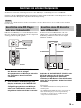
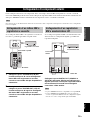
If you connect an MD player or a tape deck to the receiver,
you can enjoy audio sources played on the component.
1 Connect the TAPE/MD IN (L/R) jacks of the
receiver to the analog output jacks of an MD
player or a tape deck using a commercially
available audio pin cable.
2 To record audio output from the receiver,
connect the TAPE/MD OUT (L/R) jacks of the
receiver to the analog input jacks of an MD
player or a tape deck using a commercially
available audio pin cable.
If you connect an MD recorder or a CD recorder to the CD
player with a digital connection, you can make a digital
recording.
Connect the DIGITAL OUT (COAXIAL or
OPTICAL) jack of the CD player to the digital
input (coaxial or optical) jack of an MD recorder
or a CD recorder using a commercially available
coaxial or optical cable.
• The DIGITAL OUT jacks are compatible with PCM signals.
• The DIGITAL OUT (OPTICAL) jack is designed based on EIA
standards. To make a digital connection, use an optical cable
that meets EIA standards.
Connecting External Components
Note
Connecting an MD player or a tape
deck
LR
DOCK
CD
TAPE/MD
AUX
OUT
IN
FM
GND
AM
ANTENNA
75
UNBAL.
L
R
ANALOG
OUTIN
MD player or
tape deck
Audio pin cable
Receiver
Connecting an MD recorder or a CD
recorder
Notes
L
R
LINE OUT
OPTICAL COAXIAL
DIGITAL OUT TO RX-E410
COAXIALOPTICAL
MD recorder or
CD recorder
CD player
Optical cable
or
Coaxial cable

Connecting External Components
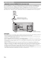
16 En
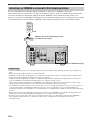
The receiver (RX-E410) is equipped with the DOCK terminal on the rear panel that allows you to connect a YAMAHA
iPod universal dock (such as YDS-10 sold separately) where you can station your iPod and control playback of your iPod
using the supplied remote control. Connect a YAMAHA iPod universal dock (such as YDS-10 sold separately) to the
DOCK terminal on the rear of the receiver using its dedicated cables. Once the connection is complete, station your iPod
in the YAMAHA iPod universal dock.
• Do not connect the power cable of the receiver, CD player, or other components to the wall outlet until all cable connections are
completed.
• Only iPod (Click and Wheel), iPod nano, and iPod mini are supported.
• You need a YAMAHA iPod universal dock (such as YDS-10 sold separately) and its dedicated cable compatible with the DOCK
terminal of the receiver.
• Do not connect any iPod accessories (such as headphones, a wired remote control, or an FM transmitter) to your iPod when it is
stationed in a YAMAHA iPod universal dock (such as YDS-10 sold separately).
• Unless your iPod is firmly stationed in a YAMAHA iPod universal dock (such as YDS-10 sold separately) connected to the DOCK
terminal of the receiver, audio signals may not be output properly.
• Once the connection between your iPod and the receiver is complete and the receiver is set to DOCK mode (see page 8), “iPod
connected” appears in the front panel display. If the connection between your iPod and the receiver fails, a status message appears in
the front panel display. For a complete list of connection status message, see the iPod section in “Troubleshooting” on page 38.
• Your iPod battery is automatically charged when your iPod is stationed in a YAMAHA iPod universal dock (such as YDS-10 sold
separately) connected to the DOCK terminal of the receiver as long as the receiver is turned on.
• Depending on the type of the iPod, you may need to insert one of the iPod adapters supplied with a YAMAHA iPod universal dock
(such as YDS-10 sold separately) into the dock slot before you station your iPod.
Connecting a YAMAHA iPod universal dock
Notes
LR
LR
AC OUTLETS
SWITCHED
MAINS
SPEAKERS
DOCK
CD
TAPE/MD
AUX
OUT
IN
FM
GND
AM
ANTENNA
75
UNBAL.
TO CDX-E410
SUBWOOFER
OUT
100W MAX. TOTAL
6
MIN / SPEAKER
Receiver (Europe model)
YAMAHA iPod universal dock
(such as YDS-10 sold separately)
iPod

CONNECTING THE POWER CABLES
17 En
English
PREPARATION
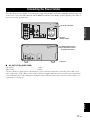
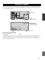
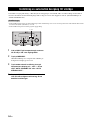
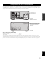
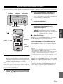
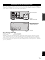
Once all connections are complete, connect the power cable of the CD player to the AC OUTLET(S) terminal on the rear
of the receiver (or the AC wall outlet if the AC OUTLET(S) terminal is not available), and then plug the power cable of
the receiver into the AC wall outlet.
■ AC OUTLET(S) (SWITCHED)
U.K. model............................................................. 1 outlet
Other models......................................................... 2 outlets
Use these outlet(s) to supply power to the CD player or any connected components. Connect the power cable of your
other components to these outlet(s). Power to these outlet(s) is supplied when the receiver is turned on. For information
on the maximum power or the total power consumption of the components that can be connected to these outlet(s), see
“Specifications” on page 44.
Connecting the Power Cables
LR
LR
MAINS
SPEAKERS
DOCK
CD
TAPE/MD
AUX
OUT
IN
FM
GND
AM
ANTENNA
75
UNBAL.
TO CDX-E410
SUBWOOFER
OUT
AC OUTLETS
SWITCHED
100W MAX. TOTAL
6
MIN / SPEAKER
L
R
LINE OUT
OPTICAL COAXIAL
DIGITAL OUT TO RX-E410
MAINS
CD player
Receiver
(Europe model)
To the AC wall outlet
To AC OUTLET(S) on the
rear panel of the receiver
(or the AC wall outlet )
Seite laden ...
Seite laden ...
Seite laden ...
Seite laden ...
Seite laden ...
Seite laden ...
Seite laden ...
Seite laden ...
Seite laden ...
Seite laden ...
Seite laden ...
Seite laden ...
Seite laden ...
Seite laden ...
Seite laden ...
Seite laden ...
Seite laden ...
Seite laden ...
Seite laden ...
Seite laden ...
Seite laden ...
Seite laden ...
Seite laden ...
Seite laden ...
Seite laden ...
Seite laden ...
Seite laden ...
Seite laden ...
Seite laden ...
Seite laden ...
Seite laden ...
Seite laden ...
Seite laden ...
Seite laden ...
Seite laden ...
Seite laden ...
Seite laden ...
Seite laden ...
Seite laden ...
Seite laden ...
Seite laden ...
Seite laden ...
Seite laden ...
Seite laden ...
Seite laden ...
Seite laden ...
Seite laden ...
Seite laden ...
Seite laden ...
Seite laden ...
Seite laden ...
Seite laden ...
Seite laden ...
Seite laden ...
Seite laden ...
Seite laden ...
Seite laden ...
Seite laden ...
Seite laden ...
Seite laden ...
Seite laden ...
Seite laden ...
Seite laden ...
Seite laden ...
Seite laden ...
Seite laden ...
Seite laden ...
Seite laden ...
Seite laden ...
Seite laden ...
Seite laden ...
Seite laden ...
Seite laden ...
Seite laden ...
Seite laden ...
Seite laden ...
Seite laden ...
Seite laden ...
Seite laden ...
Seite laden ...
Seite laden ...
Seite laden ...
Seite laden ...
Seite laden ...
Seite laden ...
Seite laden ...
Seite laden ...
Seite laden ...
Seite laden ...
Seite laden ...
Seite laden ...
Seite laden ...
Seite laden ...
Seite laden ...
Seite laden ...
Seite laden ...
Seite laden ...
Seite laden ...
Seite laden ...
Seite laden ...
Seite laden ...
Seite laden ...
Seite laden ...
Seite laden ...
Seite laden ...
Seite laden ...
Seite laden ...
Seite laden ...
Seite laden ...
Seite laden ...
Seite laden ...
Seite laden ...
Seite laden ...
Seite laden ...
Seite laden ...
Seite laden ...
Seite laden ...
Seite laden ...
Seite laden ...
Seite laden ...
Seite laden ...
Seite laden ...
Seite laden ...
Seite laden ...
Seite laden ...
Seite laden ...
Seite laden ...
Seite laden ...
Seite laden ...
Seite laden ...
Seite laden ...
Seite laden ...
Seite laden ...
Seite laden ...
Seite laden ...
Seite laden ...
Seite laden ...
Seite laden ...
Seite laden ...
Seite laden ...
Seite laden ...
Seite laden ...
Seite laden ...
Seite laden ...
Seite laden ...
Seite laden ...
Seite laden ...
Seite laden ...
Seite laden ...
Seite laden ...
Seite laden ...
Seite laden ...
Seite laden ...
Seite laden ...
Seite laden ...
Seite laden ...
Seite laden ...
Seite laden ...
Seite laden ...
Seite laden ...
Seite laden ...
Seite laden ...
Seite laden ...
Seite laden ...
Seite laden ...
Seite laden ...
Seite laden ...
Seite laden ...
Seite laden ...
Seite laden ...
Seite laden ...
Seite laden ...
Seite laden ...
Seite laden ...
Seite laden ...
Seite laden ...
Seite laden ...
Seite laden ...
Seite laden ...
Seite laden ...
Seite laden ...
Seite laden ...
Seite laden ...
Seite laden ...
Seite laden ...
Seite laden ...
Seite laden ...
Seite laden ...
Seite laden ...
Seite laden ...
Seite laden ...
Seite laden ...
Seite laden ...
Seite laden ...
Seite laden ...
Seite laden ...
Seite laden ...
Seite laden ...
Seite laden ...
Seite laden ...
Seite laden ...
Seite laden ...
Seite laden ...
Seite laden ...
Seite laden ...
Seite laden ...
Seite laden ...
Seite laden ...
Seite laden ...
Seite laden ...
Seite laden ...
Seite laden ...
Seite laden ...
Seite laden ...
Seite laden ...
Seite laden ...
Seite laden ...
Seite laden ...
Seite laden ...
Seite laden ...
Seite laden ...
Seite laden ...
Seite laden ...
Seite laden ...
Seite laden ...
Seite laden ...
Seite laden ...
Seite laden ...
Seite laden ...
Seite laden ...
Seite laden ...
Seite laden ...
Seite laden ...
Seite laden ...
Seite laden ...
Seite laden ...
Seite laden ...
Seite laden ...
Seite laden ...
Seite laden ...
Seite laden ...
Seite laden ...
Seite laden ...
Seite laden ...
Seite laden ...
Seite laden ...
Seite laden ...
Seite laden ...
Seite laden ...
Seite laden ...
Seite laden ...
Seite laden ...
Seite laden ...
Seite laden ...
Seite laden ...
Seite laden ...
Seite laden ...
Seite laden ...
Seite laden ...
Seite laden ...
Seite laden ...
Seite laden ...
Seite laden ...
Seite laden ...
Seite laden ...
Seite laden ...
Seite laden ...
Seite laden ...
Seite laden ...
Seite laden ...
Seite laden ...
Seite laden ...
Seite laden ...
Seite laden ...
Seite laden ...
Seite laden ...
Seite laden ...
Seite laden ...
Seite laden ...
Seite laden ...
Seite laden ...
Seite laden ...
Seite laden ...
Seite laden ...
Seite laden ...
Seite laden ...
Seite laden ...
Seite laden ...
Seite laden ...
Seite laden ...
Seite laden ...
Seite laden ...
Seite laden ...
Seite laden ...
Seite laden ...
Seite laden ...
Seite laden ...
Seite laden ...
Seite laden ...
Seite laden ...
Seite laden ...
Seite laden ...
Seite laden ...
Seite laden ...
Seite laden ...
Seite laden ...
Seite laden ...
Seite laden ...
Seite laden ...
Seite laden ...
Seite laden ...
Seite laden ...
Seite laden ...
Seite laden ...
Seite laden ...
Seite laden ...
Seite laden ...
Seite laden ...
Seite laden ...
Seite laden ...
Seite laden ...
Seite laden ...
Seite laden ...
Seite laden ...
Seite laden ...
Seite laden ...
Seite laden ...
Seite laden ...
Seite laden ...
Seite laden ...
Seite laden ...
Seite laden ...
Seite laden ...
Seite laden ...
Seite laden ...
Seite laden ...
Seite laden ...
Seite laden ...
Seite laden ...
Seite laden ...
Seite laden ...
Seite laden ...
Seite laden ...
Seite laden ...
Seite laden ...
-
 1
1
-
 2
2
-
 3
3
-
 4
4
-
 5
5
-
 6
6
-
 7
7
-
 8
8
-
 9
9
-
 10
10
-
 11
11
-
 12
12
-
 13
13
-
 14
14
-
 15
15
-
 16
16
-
 17
17
-
 18
18
-
 19
19
-
 20
20
-
 21
21
-
 22
22
-
 23
23
-
 24
24
-
 25
25
-
 26
26
-
 27
27
-
 28
28
-
 29
29
-
 30
30
-
 31
31
-
 32
32
-
 33
33
-
 34
34
-
 35
35
-
 36
36
-
 37
37
-
 38
38
-
 39
39
-
 40
40
-
 41
41
-
 42
42
-
 43
43
-
 44
44
-
 45
45
-
 46
46
-
 47
47
-
 48
48
-
 49
49
-
 50
50
-
 51
51
-
 52
52
-
 53
53
-
 54
54
-
 55
55
-
 56
56
-
 57
57
-
 58
58
-
 59
59
-
 60
60
-
 61
61
-
 62
62
-
 63
63
-
 64
64
-
 65
65
-
 66
66
-
 67
67
-
 68
68
-
 69
69
-
 70
70
-
 71
71
-
 72
72
-
 73
73
-
 74
74
-
 75
75
-
 76
76
-
 77
77
-
 78
78
-
 79
79
-
 80
80
-
 81
81
-
 82
82
-
 83
83
-
 84
84
-
 85
85
-
 86
86
-
 87
87
-
 88
88
-
 89
89
-
 90
90
-
 91
91
-
 92
92
-
 93
93
-
 94
94
-
 95
95
-
 96
96
-
 97
97
-
 98
98
-
 99
99
-
 100
100
-
 101
101
-
 102
102
-
 103
103
-
 104
104
-
 105
105
-
 106
106
-
 107
107
-
 108
108
-
 109
109
-
 110
110
-
 111
111
-
 112
112
-
 113
113
-
 114
114
-
 115
115
-
 116
116
-
 117
117
-
 118
118
-
 119
119
-
 120
120
-
 121
121
-
 122
122
-
 123
123
-
 124
124
-
 125
125
-
 126
126
-
 127
127
-
 128
128
-
 129
129
-
 130
130
-
 131
131
-
 132
132
-
 133
133
-
 134
134
-
 135
135
-
 136
136
-
 137
137
-
 138
138
-
 139
139
-
 140
140
-
 141
141
-
 142
142
-
 143
143
-
 144
144
-
 145
145
-
 146
146
-
 147
147
-
 148
148
-
 149
149
-
 150
150
-
 151
151
-
 152
152
-
 153
153
-
 154
154
-
 155
155
-
 156
156
-
 157
157
-
 158
158
-
 159
159
-
 160
160
-
 161
161
-
 162
162
-
 163
163
-
 164
164
-
 165
165
-
 166
166
-
 167
167
-
 168
168
-
 169
169
-
 170
170
-
 171
171
-
 172
172
-
 173
173
-
 174
174
-
 175
175
-
 176
176
-
 177
177
-
 178
178
-
 179
179
-
 180
180
-
 181
181
-
 182
182
-
 183
183
-
 184
184
-
 185
185
-
 186
186
-
 187
187
-
 188
188
-
 189
189
-
 190
190
-
 191
191
-
 192
192
-
 193
193
-
 194
194
-
 195
195
-
 196
196
-
 197
197
-
 198
198
-
 199
199
-
 200
200
-
 201
201
-
 202
202
-
 203
203
-
 204
204
-
 205
205
-
 206
206
-
 207
207
-
 208
208
-
 209
209
-
 210
210
-
 211
211
-
 212
212
-
 213
213
-
 214
214
-
 215
215
-
 216
216
-
 217
217
-
 218
218
-
 219
219
-
 220
220
-
 221
221
-
 222
222
-
 223
223
-
 224
224
-
 225
225
-
 226
226
-
 227
227
-
 228
228
-
 229
229
-
 230
230
-
 231
231
-
 232
232
-
 233
233
-
 234
234
-
 235
235
-
 236
236
-
 237
237
-
 238
238
-
 239
239
-
 240
240
-
 241
241
-
 242
242
-
 243
243
-
 244
244
-
 245
245
-
 246
246
-
 247
247
-
 248
248
-
 249
249
-
 250
250
-
 251
251
-
 252
252
-
 253
253
-
 254
254
-
 255
255
-
 256
256
-
 257
257
-
 258
258
-
 259
259
-
 260
260
-
 261
261
-
 262
262
-
 263
263
-
 264
264
-
 265
265
-
 266
266
-
 267
267
-
 268
268
-
 269
269
-
 270
270
-
 271
271
-
 272
272
-
 273
273
-
 274
274
-
 275
275
-
 276
276
-
 277
277
-
 278
278
-
 279
279
-
 280
280
-
 281
281
-
 282
282
-
 283
283
-
 284
284
-
 285
285
-
 286
286
-
 287
287
-
 288
288
-
 289
289
-
 290
290
-
 291
291
-
 292
292
-
 293
293
-
 294
294
-
 295
295
-
 296
296
-
 297
297
-
 298
298
-
 299
299
-
 300
300
-
 301
301
-
 302
302
-
 303
303
-
 304
304
-
 305
305
-
 306
306
-
 307
307
-
 308
308
-
 309
309
-
 310
310
-
 311
311
-
 312
312
-
 313
313
-
 314
314
-
 315
315
-
 316
316
-
 317
317
-
 318
318
-
 319
319
-
 320
320
-
 321
321
-
 322
322
-
 323
323
-
 324
324
-
 325
325
-
 326
326
-
 327
327
-
 328
328
-
 329
329
-
 330
330
-
 331
331
-
 332
332
-
 333
333
-
 334
334
-
 335
335
-
 336
336
-
 337
337
-
 338
338
-
 339
339
-
 340
340
-
 341
341
-
 342
342
-
 343
343
-
 344
344
-
 345
345
-
 346
346
-
 347
347
-
 348
348
-
 349
349
-
 350
350
-
 351
351
-
 352
352
-
 353
353
-
 354
354
-
 355
355
-
 356
356
-
 357
357
-
 358
358
-
 359
359
-
 360
360
-
 361
361
-
 362
362
-
 363
363
-
 364
364
-
 365
365


Yamaha MCR-E410 Bedienungsanleitung
- Kategorie
- CD-Spieler
- Typ
- Bedienungsanleitung
- Dieses Handbuch ist auch geeignet für
in anderen Sprachen
- English: Yamaha MCR-E410 Owner's manual
- français: Yamaha MCR-E410 Le manuel du propriétaire
- español: Yamaha MCR-E410 El manual del propietario
- italiano: Yamaha MCR-E410 Manuale del proprietario
- русский: Yamaha MCR-E410 Инструкция по применению
- Nederlands: Yamaha MCR-E410 de handleiding
- dansk: Yamaha MCR-E410 Brugervejledning
- svenska: Yamaha MCR-E410 Bruksanvisning
- Türkçe: Yamaha MCR-E410 El kitabı
- suomi: Yamaha MCR-E410 Omistajan opas
- română: Yamaha MCR-E410 Manualul proprietarului
Verwandte Papiere
-
Yamaha CRX-E320 Bedienungsanleitung
-
Yamaha CDX-397 Bedienungsanleitung
-
Yamaha YDS-11 Bedienungsanleitung
-
Yamaha MCR-640 Bedienungsanleitung
-
-
-
-
Yamaha RX-V563 Bedienungsanleitung
-
-
Yamaha RX-V661 Bedienungsanleitung