Kicker 2017 KXM 8-Channel Amplifier Bedienungsanleitung
- Kategorie
- Musikinstrumentenverstärker
- Typ
- Bedienungsanleitung

KXMA800.8
Manual del Propietario | Español
AMPLIFICADOR DEL LA SERIE KXM.8
Benutzerhandbuch | Deutsch
VERSTÄRKER DER KXM.8-SERIE
Manuel d’utilisation | Française
AMPLIFICATEUR DE SÉRIE KXM.8
KXM
AMPLIFIERS
Owner’s Manual
2017 KXM 8-CH Amp Rev D.indd 12017 KXM 8-CH Amp Rev D.indd 1 10/7/2019 2:21:06 PM10/7/2019 2:21:06 PM

2
KXM.8 SERIES AMPLIFIERS
OWNER’S MANUAL
INSTALLATION
Mounting: Choose a structurally sound location to mount your KICKER amplifi er. Make sure there are no
items behind the area where the screws will be driven. Choose a location that allows at least 4” (10cm)
of open ventilation for the amplifi er. If possible, mount the amplifi er in the climate-controlled passenger
compartment. Drill four holes using a 7/64” (3mm) bit and use the supplied #8 screws to mount the
amplifi er.
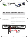
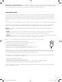
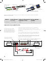
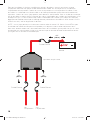
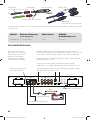
Wiring: The KXM amplifi er’s RCA inputs will receive either high or low level signals from your car stereo’s
source unit. A high-level signal can be run from the source unit’s speaker outputs to the stereo RCA
input on the end panel of the amplifi er using the KICKER KISL as shown. Alternatively, the signal can be
delivered to the amplifi er using the low-level RCA outputs on the source unit. Keep the audio signal cable
away from factory wiring harnesses and other power wiring. If you need to cross this wiring, cross it at a
90 degree angle.
PERFORMANCE
MODEL: KXMA800.8
IMPORTANT SAFETY WARNING
PROLONGED CONTINUOUS OPERATION OF AN AMPLIFIER, SPEAKER, OR SUBWOOFER
IN A DISTORTED, CLIPPED OR OVER-POWERED MANNER CAN CAUSE YOUR AUDIO
SYSTEM TO OVERHEAT, POSSIBLY CATCHING FIRE AND RESULTING IN SERIOUS
DAMAGE TO YOUR COMPONENTS AND/OR VEHICLE. AMPLIFIERS REQUIRE UP TO 4
INCHES (10CM) OPEN VENTILATION. SUBWOOFERS SHOULD BE MOUNTED WITH AT
LEAST 1 INCH (2.5CM) CLEARANCE BETWEEN THE FRONT OF THE SPEAKER AND ANY
SURFACE.
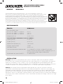
Model: KXMA800.8
RMS Power
@ 14.4V, 4 stereo, ≤ 1% THD+N
@ 14.4V, 2 stereo, ≤ 1% THD+N
@ 14.4V, 4Ω mono, ≤ 1% THD+N
50 x 8
100 x 8
200 x 4
Length [in, cm] 14-3/4, 37.4
Specifi cations common to all models:
Height [in, cm] 2-1/8, 5.5
Width [in, cm] 8-5/16, 21
Frequency Response [Hz] 10Hz–20kHz
Signal-to-Noise Ratio [dB] 95dB
Input Sensitivity 250mV–10V
Selectable Electronic Crossover Off; Variable HP, 10–500Hz; Variable LP, 40–500Hz; 400Hz–
5,000Hz with 10X Switch (bandpass capable); Slope: 24dB/
octave"
KickEQ™ Bass Boost 0–18dB @ 40Hz
2017 KXM 8-CH Amp Rev D.indd 22017 KXM 8-CH Amp Rev D.indd 2 10/7/2019 2:21:24 PM10/7/2019 2:21:24 PM

3
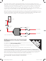
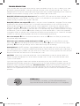
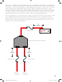
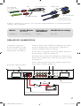
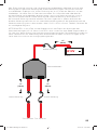
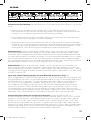
Install a fuse within 7” (18cm) of the battery and in-line with the power cable connected to your amplifi er.
POWER WIRING
source unit
high-level speaker
outputs
to amplifi er
shield
+
–
core conductor
KICKER KISL (optional)
from source unit high-
level speaker outputs
OR
to amplifi er
Model External Fuse
(sold separately)
Power/Ground Wire KICKER Wiring Kit
KXMA800.8 1 x 120 Ampere 4 Gauge PK4, CK4
/
REM +12VGND
POWER
AMP3
AMP4 BRIDGED
L
+
L
-
R
+
R
-
BRIDGED
AMP1
AMP2 BRIDGED
L
+
L
-
R
+
R
-
BRIDGED
AMP1
L
R
AMP2 AMP3 AMP4
AUTO
TURN-ON
12V/DC/AUDIO
AMP2/AMP3
FADER
AMP1/AMP2
FADER
AMP3/AMP4
FADER
ON OFF ON OFF
ON OFF
OFF/ON OFF/ON
AMP1
AMP2
RADIO
DETECT
AMP3
AMP4
RADIO
DETECT
12V
Use the FADER switches to select which inputs are active with
respect to their paired output. ON will activate the second input.
for example:
If you are using a single RCA pair of inputs, set all FADER
switches to OFF.
For any amp section being driven by additional RCA input(s), set
the FADER switch(es) to ON.
If you are using all four RCA pairs of inputs, set all FADER
switches to ON.
battery
external fuse
remote turn-on (see page 6)
≤7”
(18cm)
ABYC-compliant power terminals
Amplifi er uses 304-stainless
steel screws and conformal
coated PCB for increased
weather resistance
aluminum bottom plate
audio inputs
2017 KXM 8-CH Amp Rev D.indd 32017 KXM 8-CH Amp Rev D.indd 3 10/7/2019 2:21:25 PM10/7/2019 2:21:25 PM

4
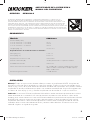
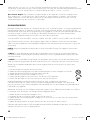
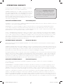
For multiple amplifi er installations where distribution blocks are used, each amplifi er should have its
proper-rated fuse, or breaker, installed between the amplifi er and the distribution block within seven inches
of the block, or on the distribution block if it provides for fusing. The primary power wire should also be
fused between the battery and distribution block, within seven inches of the battery’s B+ terminal, with
a fuse or breaker rated at least to the sum of the individual amplifi er’s fuse values, but not to exceed
1.5-times the sum of the individual fuse values (not to exceed the ampacity of the thermal insulation of the
wiring as shown in U.S.C.G. CFR33 183.425, Table 5). See the diagram below.
NOTE: Seven inches is the standard distance under U.S. Coast Guard CFR33 for placement of fuses or
breakers as required by law for new boat manufacturing. We recommend trying to adhere to this standard
in a consumer installation. Failure to do so does not mean you are breaking the law, but it does put the
safety of your boat and passengers at risk in the event of a power wire short circuit.
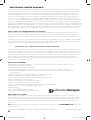
KICKER will now provide a three-year warranty with all KXA-
Series Amplifi er purchases paired with a qualifying KICKER
Installation Kit* .
This extends the standard warranty by an additional year. Amplifi er and Kit must be
purchased from an Authorized KICKER Dealer.
KICKER KXM amplifi er success is currently at an unheard-of rate, making the extended
warranty program even more benefi cial to you.
Using poor-quality, under-spec wiring kits will impede KXM amplifi er performance.
A superior-quality KICKER installation Kit is guaranteed to extend the life of KXM amplifi ers.
The new extended warranty applies only to KICKER amplifi ers and accessories sold to consumers by Authorized KICKER
Dealers in the United States of America or its possessions. It also only applies to the original purchaser of KICKER amplifi ers
and accessories. One warranty extension per amplifi er is allowed regardless of the number of amplifi er installation kits
purchased. This program does not apply to “B”-stock product or factory-refurbished product.
This offer is for a limited time, so see your local Authorized KICKER Dealer soon for details.
*U.S.A. Only | EE.UU. solamente | Nur USA | Les USA Seulement
12V
external
fuse
to amplifi er
to amplifi er
≤7”
(18cm)
external
fuse
≤7”
(18cm)
external
fuse
power distribution block
battery
≤7”
(18cm)
2017 KXM 8-CH Amp Rev D.indd 42017 KXM 8-CH Amp Rev D.indd 4 10/7/2019 2:21:26 PM10/7/2019 2:21:26 PM

5
/
REM +12VGND
POWER
AMP3
AMP4 BRIDGED
L
+
L
-
R
+
R
-
BRIDGED
AMP1
AMP2 BRIDGED
L
+
L
-
R
+
R
-
BRIDGED
AMP1
L
R
AMP2 AMP3 AMP4
AUTO
TURN-ON
12V/DC/AUDIO
AMP2/AMP3
FADER
AMP1/AMP2
FADER
AMP3/AMP4
FADER
ON OFF ON OFF
ON OFF
OFF/ON OFF/ON
AMP1
AMP2
RADIO
DETECT
AMP3
AMP4
RADIO
DETECT
/
REM +12VGND
POWER
AMP3
AMP4 BRIDGED
L
+
L
-
R
+
R
-
BRIDGED
AMP1
AMP2 BRIDGED
L
+
L
-
R
+
R
-
BRIDGED
AMP1
L
R
AMP2 AMP3 AMP4
AUTO
TURN-ON
12V/DC/AUDIO
AMP2/AMP3
FADER
AMP1/AMP2
FADER
AMP3/AMP4
FADER
ON OFF ON OFF
ON OFF
OFF/ON OFF/ON
AMP1
AMP2
RADIO
DETECT
AMP3
AMP4
RADIO
DETECT
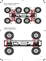
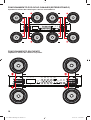
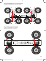
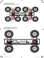
BRIDGED OPERATION
minimum impedance of 4 ohms
EIGHT CHANNEL OPERATION
minimum impedance of 2 ohm
2017 KXM 8-CH Amp Rev D.indd 52017 KXM 8-CH Amp Rev D.indd 5 10/7/2019 2:21:26 PM10/7/2019 2:21:26 PM

6
OPERATION
Automatic Turn-On Selection: The KXM series offers three different automatic turn-on modes that can
be selected on the end panel; +12V, DC Offset, and Audio. Using either the DC Offset or Audio mode
causes the REM terminal to have +12V out for turning on additional amplifi ers.
• Remote Turn-On: Set the switch to +12V to use the remote turn-on lead from your source unit. Run 18
gauge wire from the Remote Turn-On Lead on your source unit to the terminal labeled REM between the
amplifi er’s positive and negative power terminals. This is the preferred automatic turn-on method.
• DC Offset Turn-On: If Remote Turn-On is not an option, the next best setting is DC Offset. The DC Offset
mode detects a 3V DC offset from the HI-Level speaker outputs when the source unit has been turned on.
• Signal Sense Turn-On: The Audio setting is the fi nal alternative for Automatic turn-on. This is a Signal Sense
turn-on method that detects the incoming audio signal from your source unit and automatically turns on the
amp. This turn-on method will not work properly if the input gain control is not set appropriately.
Radio Detect: The RCA inputs on KICKER KXM amplifi ers are capable of receiving either Hi or Low-
level signals from your source unit. If you are using Hi-Level inputs, but your source unit cannot detect an
audio system present or refuses to play audio out of one or more speakers, you may need to set RADIO
DETECT to ON. This will activate a load resistor at the amplifi er’s inputs and tell the source unit there are
speakers present. Do NOT use Radio Detect if you are using a Low-Level input signal; doing so will greatly
reduce the input signal.
Fader Switches: Turn the Fader switch(es) OFF if you are running more than a single pair of RCA inputs
to the amplifi er. Turn the Fader switch(es) ON if you want to drive those channels from a single input. For
example, if you are using AMP 1, AMP 2, AMP 3, and AMP 4 RCA inputs, switch the AMP 1/AMP 2
FADER, AMP 2/AMP 3 FADER , and AMP 3/AMP 4 FADER buttons to OFF.
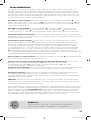
Input Gain Control with Gain Matching: The input gain control is not a volume control. It matches the
output of the source unit to the input level of the amplifi er and features Gain Matching to prevent clipping
the input. For a quick setup, turn the source unit up to about 3/4 volume (if the source unit goes to 30,
turn it to 25). KICKER recommends using the test tones at www.kicker.com/support/ to reach the most
accurate and best performing settings. Next, slowly turn (clockwise) the gain on the amplifi er up until you
see the Gain LED light up or hear audible distortion, then turn it down a little. If the GAIN knob’s backlight
comes on, the input is still clipping. For full instructions on Gain Matching, please see the next page.
Crossover Switches with Frequency Multiplier: Use the XOVER switches on the end panel of the
amplifi er to set the internal crossovers of AMPS 1 & 2 to OFF, HI-PASS, LO-PASS, or BAND-PASS
(AMP 2 only). When the switch is set to OFF, a full bandwidth signal will be amplifi ed. Set the switch to
HP if you want the amplifi er’s internal crossover to serve as a high-pass fi lter. Set the switch to LP if you
want the amplifi er’s internal crossover to serve as a low-pass fi lter. Set the switch to BP when a specifi c
frequency range is required. Never change the crossover switches with the audio system on!
Set the 1X/10X frequency multiplier switch to the setting that is appropriate for your application. A setting
of 10X will set the range of the AMP 1 crossover to 100–5,000Hz, and the crossover of AMP 2 to
100–5,000Hz.
Mini-USB for internal use only; do NOT remove or tamper. KICKER is not responsible for any damage to
equipment resulting from connections made to this port.
KXMA800.8
PRT
GAIN
110
X-OVER X-OVER X-OVER X-OVER
OFF/HP/LP OFF/HP/LP
OFF/HP/LP/BP OFF/HP/LP/BP
50010
HI-PASS
Hz
50040
LO-PASS
Hz 50010
HI-PASS
Hz 50040
LO-PASS
Hz180
KICK EQ
dB 180
KICK EQ
dB 180
KICK EQ
dB
1X/10X
LO-PASS
RANGE
1X/10X
LO-PASS
RANGE
1X/10X
RANGE
1X/10X
RANGE
50010
FREQ.
Hz 50010
FREQ.
Hz
AMP1 AMP2 AMP3 AMP4
GAIN
110
GAIN
110
180
KICK EQ
dB
GAIN
110
GAIN
MATCH
GAIN
MATCH
GAIN
MATCH
GAIN
MATCH
2017 KXM 8-CH Amp Rev D.indd 62017 KXM 8-CH Amp Rev D.indd 6 10/7/2019 2:21:26 PM10/7/2019 2:21:26 PM

7
GAIN MATCHING
In any audio system, the goal is to reach maximum input and output levels without distortion or clipping.
The engineers at KICKER have taken the guesswork, and hassle, out of matching the output voltage of
your source unit to the amplifi er with the Gain Matching feature. To begin, you’ll need to download the
KICKER test tones from www.kicker.com/test-tones. The following fi les are available in MP3 and WAV
formats:
1kHz @ 0dBFS, 50Hz @ 0dBFS, 1kHz @ -10dBFS, 50Hz @ -10dBFS, 1kHz @ -5dBFS, 50Hz @ -5dBFS
These test tones are sine waves meant to provide a consistent signal for the KX amplifi er to reference.
The different recording levels are designed to give you the perfect gain match for your application.
0dBFS: Designed for audiophile applications to give you distortion free audio output with the most
dynamic range.
-5dBFS: Designed for normal/daily applications, there will be less dynamic range but higher potential
audio output levels. With this set up you can get some occasional clipping from the amplifi er.
-10dBFS: Designed only for Subwoofer applications, there will be less dynamic range but higher potential
audio output levels. With this set up you can get some clipping from the amplifi er.
Afterwards, use the following procedure to accurately Gain Match your amplifi er(s):
1. Disconnect the speakers from the KX amplifi er.
2. Set all EQ and crossover settings to fl at on your source unit.
3. Play the downloadable fi le from KICKER.com
4. Turn the source unit up to 3/4 volume.
5. Increase the gain of the amplifi er until the Gain LED turns on.
6. Decrease the gain of the amplifi er until the Gain LED turns off.
All level matching circuitry in the KX amplifi ers is at the beginning of the signal chain. If you are going to
use features like bass boost, SHOCwave or EQ settings, it may be necessary to readjust the gain to a
lower setting to compensate for increased output at those frequencies.
Once the amp and source unit are gain matched, you will want to make certain you are not overdriving
your speakers. Use the following procedure:
1. Set the source until volume to 0.
2. Reconnect the speakers to the KX amplifi er.
3. Slowly increase the volume level of the source unit as you listen for audible distortion.
4. If you can hear clipping, decrease the gain of the amplifi er until it is gone.
Likewise, you can use the CLIP indicator feature of the KXARC remote to easily identify which amplifi er’s
output is clipping and when.
GAIN
MATCH
KICK EQ Bass Boost Control: The variable bass boost control on the side of the KXMA400.4 amplifi er
is designed to give you increased output, 0–18dB, at 40Hz. The setting for this control is subjective. If you
turn it up, you must readjust the input gain control to avoid clipping the amplifi er.
2017 KXM 8-CH Amp Rev D.indd 72017 KXM 8-CH Amp Rev D.indd 7 10/7/2019 2:21:27 PM10/7/2019 2:21:27 PM

8
TROUBLESHOOTING
If your amplifi er does not appear to be working, check the obvious things fi rst such as blown fuses, poor
or incorrect wiring connections, incorrect setting of crossover switch and gain controls, etc. There is a
Protection (PRT) LED on the side panel of your Kicker KXM series amplifi er. Depending on the state of the
amplifi er and the vehicle’s charging system, the LED will either glow red or be off.
Red (PRT) LED fl ickering with loud music? The red (PRT) LED indicates low battery voltage. Check
all the connections in your vehicle’s charging system. It may be necessary to replace or charge your
vehicle’s battery or replace your vehicle’s alternator.
Red (PRT) LED on, no output?
Amplifi er is very hot = thermal protection is engaged. Test for proper
impedance at the speaker terminals with a VOM meter (see the diagrams in this manual for minimum
recommended impedance and multiple speaker wiring suggestions). Also check for adequate airfl ow
around the amplifi er.
Amplifi er shuts down only while vehicle is running = voltage protection circuitry is
engaged. Voltage to the amplifi er is not within the 10–16 volt operating range. Have the vehicle’s charging
and electrical system inspected.
Amplifi er will only play at low volume levels = short circuit protection
is engaged. Check for speaker wires shorted to each other or to the vehicle chassis. Check for damaged
speakers or speaker(s) operating below the minimum recommended impedance.
No or low output?
Check the balance control on source unit
Check the RCA (or speaker input)
and speaker output connections.
Alternator noise-whining sound with engine’s RPM?
Check for damaged RCA (or speaker
input) cable
Check the routing of RCA (or speaker input) cable
Check the source unit for proper
grounding
Check the gain settings and turn them down if they are set too high.
Ground Noise? KICKER amplifi ers are engineered to be fully compatible with all manufacturers’ head
units. Some head units may require additional grounding to prevent noise from entering the audio signal. If
you are experiencing this problem with your head unit, in most cases running a ground wire from the RCA
outputs on the head unit to the chassis will remedy this issue.
CAUTION: When jump starting the vehicle, be sure that connections made with jumper cables are
correct. Improper connections can result in blown amplifi er fuses as well as the failure of other critical
systems in the vehicle.
If you have more questions about the installation or operation of your new KICKER product, see the
Authorized KICKER Dealer where you made your purchase. For more advice on installation, click on the
SUPPORT tab on the KICKER homepage, www.kicker.com. Choose the TECHNICAL SUPPORT tab,
choose the subject you are interested in, and then download or view the corresponding information.
Please E-mail support@kicker.com or call Technical Services (405) 624-8583 for unanswered or specifi c
questions.
KXMA800.8
50 x 8 @ 4 ohms, 14.4VDC, 1% THD, CEA-2006B (Watts)
Signal to Noise Ratio -75dB CEA-2006B (ref: 1W, A-weighted)
2017 KXM 8-CH Amp Rev D.indd 82017 KXM 8-CH Amp Rev D.indd 8 10/7/2019 2:21:27 PM10/7/2019 2:21:27 PM

9
Modelo:
KXMA800.8
Potencia RMS [Vatios]
a 14.4V, 4 stereo, ≤ 1% THD+N
a 14.4V, 2 stereo, ≤ 1% THD+N
a 14.4V, 4Ω mono, ≤ 1% THD+N
50 x 8
100 x 8
200 x 4
Longitud [pulg, cm] 14-3/4, 37.4
Especifi caciones en común de todos los modelos:
Altura [pulg, cm] 2-1/8, 5.5
Ancho [pulg, cm] 8-5/16, 21
Respuesta de frecuencia ± 1dB 10Hz–20kHz
Relación señal-ruido [dB] >95dB, ponderación A, re: potencia nominal
Sensibilidad de entrada 250mV–10V
Divisor de frecuencias electrónico seleccionable Off; Variable HP, 10–500Hz; Variable LP, 40–500Hz;
400Hz–5,000Hz con interruptor 10X (BP capaces);
Slope: 24dB/octave”
Refuerzo de graves KickEQ
™
0–18dB @ 40Hz
AMPLIFICADOR DE LA SERIE KXM.8
MANUAL DEL PROPIETARIO
INSTALACIÓN
Montaje: Escoja un lugar estructuralmente sólido para montar el amplifi cador KICKER. Asegúrese de
que no haya nada por detrás de dónde van a entrar los tornillos. Escoja un lugar en que queden por lo
menos 4 plg. (10 cm) de espacio abierto de ventilación alrededor del amplifi cador. Si es posible, monte el
amplifi cador en el compartimiento de pasajeros, con ambiente acondicionado. Haga cuatro agujeros con
una broca de 7/64 de plg. (3 mm) y monte el amplifi cador con los tornillos N° 8 que se suministran.
Cableado: Las entradas RCA del amplifi cador KXM recibirán señales de alto o bajo nivel desde la unidad
fuente del estéreo de su automóvil. Una señal de alto nivel se puede transmitir desde las salidas de los
altavoces de la unidad fuente hasta la entrada RCA del estéreo en el panel inferior del amplifi cador utilizando
el KICKER KISL, como se muestra en la imagen. Alternativamente, la señal se puede transmitir hacia el
amplifi cador utilizando las salidas RCA de bajo nivel en la unidad fuente. Mantenga el cable de señal de
audio lejos de los arneses de cableado de fábrica y de otros cables eléctricos. Si necesita cruzar este
cableado, hágalo a un ángulo de 90 grados.
RENDIMIENTO
MODELOS: KXMA800.8
ADVERTENCIA IMPORTANTE DE SEGURIDAD: LA OPERACIÓN PROLONGADA Y CONTINUA DE UN
AMPLIFICADOR DE MANERA DISTORSIONADA O CORTADA PUEDE PROVOCAR QUE SU SISTEMA DE
AUDIO SE SOBRECALIENTE CON LA POSIBILIDAD DE INCENDIARSE Y PROVOCAR DAÑOS GRAVES A SUS
COMPONENTES O VEHÍCULO. ¡LOS PRODUCTOS KICKER PUEDEN PRODUCIR NIVELES DE SONIDO QUE
PUEDEN DAÑAR PERMANENTEMENTE SU OÍDO! SUBIR EL VOLUMEN DE UN SISTEMA A UN NIVEL EN EL
CUAL SE ESCUCHA UNA DISTORSIÓN ES MÁS DAÑINO PARA SUS OÍDOS QUE ESCUCHAR UN SISTEMA SIN
DISTORSIÓN AL MISMO NIVEL DE VOLUMEN. EL UMBRAL DEL DOLOR ES SIEMPRE UN INDICADOR DE QUE
EL NIVEL DEL SONIDO ES MUY ALTO Y PUEDE DAÑAR PERMANENTEMENTE SU AUDICIÓN. USE EL SENTIDO
COMÚN AL CONTROLAR EL VOLUMEN.
2017 KXM 8-CH Amp Rev D.indd 92017 KXM 8-CH Amp Rev D.indd 9 10/7/2019 2:21:27 PM10/7/2019 2:21:27 PM

10
/
REM +12VGND
POWER
AMP3
AMP4 BRIDGED
L
+
L
-
R
+
R
-
BRIDGED
AMP1
AMP2 BRIDGED
L
+
L
-
R
+
R
-
BRIDGED
AMP1
L
R
AMP2 AMP3 AMP4
AUTO
TURN-ON
12V/DC/AUDIO
AMP2/AMP3
FADER
AMP1/AMP2
FADER
AMP3/AMP4
FADER
ON OFF ON OFF
ON OFF
OFF/ON OFF/ON
AMP1
AMP2
RADIO
DETECT
AMP3
AMP4
RADIO
DETECT
12V
batería
fusible externo
encendido a distancia (página 13)
≤7”
(18cm)
Modelo Fusible Externo
(no incluido)
Cable de Alimentación y
Conexión a Tierra
Kit de cableado
KICKER
KXMA800.8 1 x 120 Ampere Calibre 4 PK4, CK4
Cable de salida
de altavoz de
alto nivel
Hacia el amplifi cador
Hacia el
amplifi cador
Conexión a tierra o blindaje
+
–
cable central
Instale un fusible a menos de 7 plg. (18 cm) de la batería y en línea con el cable de alimentación
conectado al amplifi cador.
KICKER KISL
Cable de salida de
altavoz de alto nivel
O
CABLEADO DE ALIMENTACIÓN
Placa con fondo
de aluminio
El amplifi cador utiliza tornillos
de acero inoxidable tipo 304 y
placa de circuito impreso con
recubrimiento conformado para
una mayor resistencia al clima.
Terminales de energía
aprobados por ABYC
Use los interruptores del ATENUADOR para seleccionar
las entradas que estarán activas con respecto a su salida
sincronizada. El modo ACTIVADO activará la segunda entrada.
Por ejemplo:
Si usa un solo par de entradas de RCA, coloque todos los
interruptores del ATENUADOR en posición DESACTIVADO.
Para toda sección del amplifi cador que esté impulsada por
entradas de RCA adicionales, coloque los interruptores del
ATENUADOR en posición ACTIVADO.
Si usa los cuatro pares de entradas de RCA, coloque todos los
interruptores del ATENUADOR en posición ACTIVADO.
2017 KXM 8-CH Amp Rev D.indd 102017 KXM 8-CH Amp Rev D.indd 10 10/7/2019 2:21:28 PM10/7/2019 2:21:28 PM

11
Para varias instalaciones de amplifi cadores donde se utilizan bloques de distribución, cada amplifi cador
debe poseer su fusible de grado apropiado, o interruptor, instalado entre el amplifi cador y el bloque de
distribución a siete pulgadas del bloque, o sobre el bloque de distribución si admite fusibles. El principal
cable de alimentación también debe fusionarse entre la batería y el bloque de distribución, a siete
pulgadas del terminal B+ de la batería, con un fusible o interruptor con una clasifi cación al menos de la
suma de los valores individuales del fusible del amplifi cador, pero que no supere 1,5 veces la suma de
los valores individuales del fusible (que no supere la ampacidad del aislamiento térmico del cableado
como se demuestra en U.S.C.G. CFR33 183.425, Tabla 5). Vea el siguiente diagrama.
NOTA: Siete pulgadas es la distancia estándar según la Guardia Costera de los Estados Unidos, CFR33,
para la colocación de fusibles o interruptores como lo requiere la ley para la fabricación de nuevos
barcos. Recomendamos cumplir con este estándar en caso de ser instalado por el consumidor. El no
hacerlo no signifi ca que no cumple con la ley, pero pone en riesgo la seguridad de su barco y de los
pasajeros en caso de cortocircuito eléctrico.
12V
fusible externo
Hacia el
amplifi cador
Hacia el
amplifi cador
≤7”
(18cm)
fusible externo
≤7”
(18cm)
≤7”
(18cm)
fusible externo
Bloqueo de distribución de energía
batería
2017 KXM 8-CH Amp Rev D.indd 112017 KXM 8-CH Amp Rev D.indd 11 10/7/2019 2:21:28 PM10/7/2019 2:21:28 PM

12
/
REM +12VGND
POWER
AMP3
AMP4 BRIDGED
L
+
L
-
R
+
R
-
BRIDGED
AMP1
AMP2 BRIDGED
L
+
L
-
R
+
R
-
BRIDGED
AMP1
L
R
AMP2 AMP3 AMP4
AUTO
TURN-ON
12V/DC/AUDIO
AMP2/AMP3
FADER
AMP1/AMP2
FADER
AMP3/AMP4
FADER
ON OFF ON OFF
ON OFF
OFF/ON OFF/ON
AMP1
AMP2
RADIO
DETECT
AMP3
AMP4
RADIO
DETECT
/
REM +12VGND
POWER
AMP3
AMP4 BRIDGED
L
+
L
-
R
+
R
-
BRIDGED
AMP1
AMP2 BRIDGED
L
+
L
-
R
+
R
-
BRIDGED
AMP1
L
R
AMP2 AMP3 AMP4
AUTO
TURN-ON
12V/DC/AUDIO
AMP2/AMP3
FADER
AMP1/AMP2
FADER
AMP3/AMP4
FADER
ON OFF ON OFF
ON OFF
OFF/ON OFF/ON
AMP1
AMP2
RADIO
DETECT
AMP3
AMP4
RADIO
DETECT
FUNCIONAMIENTO EN PUENTE
impedancia mínima de 4 ohmios en puente
FUNCIONAMIENTO POR OCHO CANALES (ESTEREOFÓNICO)
impedancia mínima de 2 ohmio por canal en estereofónico
2017 KXM 8-CH Amp Rev D.indd 122017 KXM 8-CH Amp Rev D.indd 12 10/7/2019 2:21:28 PM10/7/2019 2:21:28 PM

13
Selección de Encendido Automático: La serie KXM ofrece dos modalidades de encendido automático que:
+12V, y compensación de CC.
• Encendido a Distancia: Instale cable calibre 18 desde el conductor de encendido a distancia de la unidad
fuente hasta la terminal etiquetada REM entre las terminales de alimentación positiva y negativa del
amplifi cador.
• Encendido por Compensación de CC: En la modalidad de compensación de CC, el amplifi cador detecta una
subida de 3V de las salidas de altavoz de alto nivel cuando la unidad fuente se ha encendido.
• Encendido por Detección de Señal: La modalidad de es la opción fi nal de encendido automático. Este es
un método de encendido en que el amplifi cador detecta la señal de audio procedente de la unidad fuente
y se enciende automáticamente. Este método de encendido no funciona correctamente si el control de
amplifi cación de entrada no se ha fi jado correctamente.
Detección de radio: Las entradas RCA de los amplifi cadores KICKER KXM pueden recibir señales de alto o bajo
nivel desde la unidad fuente. Si usa entradas de alto nivel, pero su unidad fuente no puede detectar un sistema
de audio presente o rechaza la reproducción de audio en uno o más altavoces, es probable que deba activar la
Detección de radio. Esto activará un resistor de carga en las entradas del amplifi cador y comunicará a la unidad
fuente la presencia de altavoces. NO utilice la Detección de radio si usa una señal de entrada de bajo nivel; si lo
hace, se reducirá notablemente la señal de entrada.
Interruptor del atenuador: Deprima el interruptor del atenuador si está operando dos juegos de entrada
(delantero y trasero por ejemplo) al amplifi cador. Deje el interruptor del atenuador apagado si desea manejar
todos los canales desde una única entrada estéreo.
Interruptores de transición con multiplicador de frecuencia: Use los interruptores XOVER en el panel fi nal
del amplifi cador para ajustar las transiciones internas de AMPS 1 y 2 a APAGADO, PASO ALTO, PASO BAJO,
o PASO DE BANDA (únicamente AMP 2). Cuando el interruptor se ajusta a APAGADO, se amplifi cará una señal
completa de banda ancha. Ajuste el interruptor a HP si desea que la transición interna del amplifi cador sirva como
un fi ltro de paso alto. Ajuste el interruptor a LP si desea que la transición interna del amplifi cador sirva como un fi ltro
de paso bajo. Ajuste este interruptor a BP cuando requiera un rango de frecuencia específi co. ¡Nunca cambie los
interruptores de transición cuando esté encendido el sistema de audio!
Ajuste el interruptor del multiplicador de frecuencia 1X/10X a la selección que sea apropiada para su aplicación.
Un ajuste de 10X seleccionará el rango de transición de AMP 1 a 100–5,000Hz, y la transición de AMP 2 a
100–5,000Hz.
Control de ganancia de entrada con Sincronización de ganancia: El control de ganancia de entrada no es
un control de volumen. Sincroniza la salida de la unidad fuente con el nivel de entrada del amplifi cador, y cuenta
con Sincronización de ganancia para evitar recortes de la entrada. Para realizar una confi guración rápida, suba el
volumen de la unidad fuente hasta aproximadamente 3/4 (si la unidad fuente llega a 30, súbala a 25). Luego, suba
lentamente (hacia la derecha) la ganancia en el amplifi cador hasta que se encienda la luz LED de ganancia o hasta
que escuche una distorsión, luego bájela un poco. KICKER recomienda que se usen los tonos de prueba en www.
kicker.com/support/ para alcanzar los ajustes más exactos y de mejor desempeño. Si se enciende la luz de fondo
de la perilla GAIN (Ganancia), signifi ca que aún hay recorte en la entrada. Lea la siguiente página para obtener
todas las instrucciones sobre la Sincronización de ganancia.
Refuerzo de Bajos: El control variable de refuerzo de bajos ubicado en el panel de extremo del amplifi cador
ha sido diseñado para dar una mayor salida de bajos, de 0 a 18 dB a 40 Hz. La confi guración de este control es
subjetiva. Si usted lo sube, debe volver a ajustar el control de amplifi cación para evitar la limitación de la señal del
amplifi cador.
FUNCIONAMIENTO
KXMA800.8
PRT
GAIN
110
X-OVER X-OVER X-OVER X-OVER
OFF/HP/LP OFF/HP/LP
OFF/HP/LP/BP OFF/HP/LP/BP
50010
HI-PASS
Hz
50040
LO-PASS
Hz 50010
HI-PASS
Hz 50040
LO-PASS
Hz180
KICK EQ
dB 180
KICK EQ
dB 180
KICK EQ
dB
1X/10X
LO-PASS
RANGE
1X/10X
LO-PASS
RANGE
1X/10X
RANGE
1X/10X
RANGE
50010
FREQ.
Hz 50010
FREQ.
Hz
AMP1 AMP2 AMP3 AMP4
GAIN
110
GAIN
110
180
KICK EQ
dB
GAIN
110
GAIN
MATCH
GAIN
MATCH
GAIN
MATCH
GAIN
MATCH
2017 KXM 8-CH Amp Rev D.indd 132017 KXM 8-CH Amp Rev D.indd 13 10/7/2019 2:21:29 PM10/7/2019 2:21:29 PM

14
SINCRONIZACIÓN DE GANANCIA
En un sistema de audio, el objetivo es lograr los niveles máximos de entrada y salida sin distorsión ni
recortes. Con la función “Sincronización de ganancia”, los ingenieros de KICKER lograron que no sea
necesario hacer conjeturas ni complicarse a la hora de sincronizar el voltaje de salida de su unidad de
alimentación con el amplifi cador. Para comenzar, deberá descargar los tonos de prueba de KICKER
desde www.kicker.com/test-tones Los siguientes archivos están disponibles en formato MP3 y WAV:
1 kHz a 0 dBFS, 50 Hz a 0 dBFS, 1 kHz a -10 dBFS, 50 Hz a -10 dBFS, 1 kHz a -5 dBFS, 50 Hz a -5
dBFS
Estos tonos de prueba son ondas senoidales que tienen como fi n ofrecer una señal uniforme para que el
amplifi cador KX pueda tener como referencia. Los diferentes niveles de grabación están diseñados para
darle una sincronización de ganancia perfecta para su aplicación.
0 dBFS: Diseñado para aplicaciones de afi cionados a la música, para ofrecerle una salida de audio sin
distorsiones con el rango más dinámico.
-5 dBFS: Diseñado para aplicaciones normales/diarias, ofrece menos rango dinámico, pero niveles
de salida de audio potencialmente más altos. Con esta confi guración, puede haber algunos recortes
ocasionales desde el amplifi cador.
-10 dBFS: Diseñado únicamente para aplicaciones de subwoofers, ofrece menos rango dinámico, pero
niveles de salida de audio potencialmente más altos. Con esta confi guración, puede haber algunos
recortes desde el amplifi cador.
A continuación, siga este procedimiento para Sincronizar ganancia en forma precisa en sus
amplifi cadores:
1. Desconecte los altavoces del amplifi cador KX.
2. Coloque todos los ajustes del ecualizador y del divisor de frecuencias en plano en su
unidad de alimentación.
3. Reproduzca el archivo descargado desde KICKER.com.
4. Suba el volumen de la unidad de alimentación a 3/4 de su capacidad.
5. Aumente la ganancia del amplifi cador hasta que se encienda la luz LED de ganancia.
6. Disminuya la ganancia del amplifi cador hasta que se apague la luz LED de ganancia.
Todos los circuitos de sincronización de nivel de los amplifi cadores KX están al inicio de la cadena de
señal. Si va a utilizar funciones como el potencializador de graves, SHOCwave o confi guraciones del
ecualizador, es posible que necesite reajustar la ganancia a una confi guración inferior para compensar
una mayor salida en esas frecuencias.
Cuando el amplifi cador y la unidad de alimentación tienen la ganancia sincronizada, debería asegurarse
de no usar los altavoces excesivamente. Use el siguiente procedimiento:
1. Establezca el volumen de la unidad de alimentación en 0.
2. Vuelva a conectar los altavoces al amplifi cador KX.
3. Aumente en forma lenta el nivel de volumen de la unidad de alimentación a medida que escucha para
detectar si hay distorsión.
4. Si oye recortes, disminuya la ganancia del amplifi cador hasta que hayan desaparecido.
De la misma forma, puede utilizar la función del indicador CLIP del control remoto KXARC para identifi car
con facilidad cuál es el amplifi cador cuya salida tiene recortes, y en qué momento los tiene.
GAIN
MATCH
2017 KXM 8-CH Amp Rev D.indd 142017 KXM 8-CH Amp Rev D.indd 14 10/7/2019 2:21:29 PM10/7/2019 2:21:29 PM

15
RESOLUCIÓN DE PROBLEMAS
Si su amplifi cador parece no estar funcionando, revise lo obvio primero: fusibles quemados, conexiones malas o incorrectas,
posición incorrecta de los selectores de crossover y amplifi cación, etc. Su amplifi cador modelo KXM de KICKER cuenta
con los LED de protección (PRT) y de encendido (PWR) en el panel de alimentación lateral. Dependiendo del estado del
amplifi cador y del sistema de carga del vehículo, los LED se iluminarán en verde o en rojo. Cuando el LED se ilumina en verde,
indica que el amplifi cador está encendido y no hay ningún problema.
¿El indicador luminoso LED verde está apagado y no hay salida? Con un voltímetro/ohmímetro (VOM), verifi que
lo siguiente:
Hay +12V en la terminal de alimentación (debe leerse entre +12V y +16V).
Hay +12V en la terminal de
encendido a distancia (debe leerse entre +12V y +16V).
No hay conexiones invertidas de alimentación o conexión a tierra.
La terminal de conexión a tierra tiene la conductividad adecuada.
No hay fusibles quemados.
¿El Indicador luminoso LED verde está encendido y no hay salida? Verifi que lo siguiente:
Las conexiones RCA
están bien.
Las salidas de altavoces están bien pues han sido puestas a prueba con un altavoz en buenas condiciones.
Se ha cambiado la unidad fuente por una unidad fuente en buenas condiciones.
Con un medidor VOM confi gurado para
medir voltaje de “CA”, se ha buscado una señal en el cable RCA que alimenta el amplifi cador.
¿El indicador luminoso LED de “protection” destella con la música fuerte? El indicador luminoso LED rojo indica
que hay bajo voltaje de batería. Revise todas las conexiones del sistema de carga eléctrica del vehículo. Puede ser necesario
cambiar o cargar la batería del vehículo o cambiar el alternador del vehículo.
¿El indicador luminoso LED de “protection” está encendido y no hay salida?
El amplifi cador está muy caliente
= Se ha activado el circuito de protección térmica. Con un medidor VOM, compruebe que las terminales de altavoz tengan
la impedancia correcta (vea en este manual los diagramas que contienen datos de impedancia mínima recomendada y
sugerencias de cableado de varios altavoces). Asegúrese también de que haya un fl ujo de aire adecuado alrededor del
amplifi cador.
El amplifi cador se apaga sólo cuando el vehículo está en marcha = Se ha activado el circuito de protección
contra sobrevoltaje. El voltaje al amplifi cador no está dentro del intervalo de funcionamiento de 10V a 16V. Haga inspeccionar
el sistema eléctrico y de carga eléctrica del automóvil.
El amplifi cador sólo funciona a bajo volumen = Se ha activado el
circuito de protección contra cortocircuitos. Asegúrese de que los cables de los altavoces no estén en cortocircuito entre sí o
con el chasis del vehículo. Vea si hay altavoces dañados o funcionando a menos de la impedancia mínima recomendada.
¿No hay salida de uno de los canales?
Revise el control de balance de la unidad fuente.
Revise las conexiones RCA
(o de entrada de altavoz) y de salida de altavoz del canal.
¿Hay ruido sibilante de alternador asociado a las RPM del motor?
Vea si hay algún cable RCA (o de entrada
de altavoz) dañado.
Revise el encaminamiento del cable RCA (o de entrada de altavoz).
Vea si la unidad fuente tiene
conexión a tierra apropiada.
Revise las confi guraciones de amplifi cación y bájelas si están muy altas.
¿Hay baja respuesta de bajos? Invierta la conexión de uno de los altavoces de positiva a negativa en los canales
estereofónicos y/o de subwoofer; si los bajos mejoran, el altavoz estaba fuera de fase.
¿Hay ruido de conexión a tierra? Los amplifi cadores KICKER son totalmente compatibles con las unidades fuente de
todos los fabricantes. Algunas unidades principales pueden necesitar más conexión a tierra para evitar que entre ruido a la
señal de audio. En la mayoría de los casos, este problema con la unidad principal se resuelve instalando un cable de conexión
a tierra desde las salidas RCA de la unidad principal al chasis.
PRECAUCIÓN: Cuando haga arrancar el vehículo con cables de arranque conectados a una batería externa, asegúrese de
que las conexiones de los cables de arranque sean correctas. Conectar los cables de arranque de manera incorrecta puede
quemar los fusibles del amplifi cador y causar fallas en otros sistemas del vehículo.
Si tiene más preguntas sobre la instalación de su nuevo producto KICKER, vaya al distribuidor autorizado de KICKER donde
lo compró. Si necesita más consejos sobre la instalación, haga clic en la lengüeta SUPPORT (apoyo) de la página Web de
KICKER, www.KICKER.com. Escoja la lengüeta TECHNICAL SUPPORT (apoyo técnico), escoja el tema que le interese
y luego descargue o vea la información correspondiente. Envíe un mensaje por correo electrónico a [email protected]
o comuníquese con Servicios Técnicos llamando al (405) 624-8583 si tiene preguntas específi cas o a las cuales no haya
encontrado respuesta.
KXMA800.8
50 x 8 @ 4 ohmios, 14.4VCC, 1% THD, CEA-2006B (W)
Relación de Señal a Ruido -75dB CEA-2006 (ref: 1W, ponderado en A)
2017 KXM 8-CH Amp Rev D.indd 152017 KXM 8-CH Amp Rev D.indd 15 10/7/2019 2:21:29 PM10/7/2019 2:21:29 PM

16
Modèle:
KXMA800.8
Puissance RMS, Watts
@ 14.4V, 4 stereo, ≤ 1% THD+N
@ 14.4V, 2 stereo, ≤ 1% THD+N
@ 14.4V, 4Ω mono, ≤ 1% THD+N
50 x 8
100 x 8
200 x 4
Longueur [po, cm] 14-3/4, 37,4
Caractéristiques communes à tous les modèles :
Hauteur [po, cm] 2-1/8, 5,5
Largeur [po, cm] 8-5/16, 21
Réponse en fréquence [Hz] 10Hz–20kHz
Rapport signal-bruit [dB] >95dB
Sensibilité d’Entrée 250mV–10V
Crossover électronique sélectionnable Off; Variable HP, 10–500Hz; Variable LP, 40–500Hz;
400Hz–5,000Hz avec commutateur multiplicateur par 10
(passe-bande capable); Slope: 24dB/octave”
Amplifi cation des graves KickEQ™ 0–18dB @ 40Hz
AMPLIFICATEUR SÉRIE KXM.8
MANUEL D’UTILISATION
INSTALLATION
Montage: Choisissez un emplacement de structure saine pour monter votre amplifi cateur KICKER.
Assurez-vous que l’arrière de l’emplacement où vous allez enfoncer les vis ne comporte aucun élément.
Choisissez un endroit assurant au moins 10 cm (4 po) de dégagement de ventilation ouverte pour
l’amplifi cateur. Si possible, montez l’amplifi cateur dans l’habitacle passager climatisé. Percez quatre trous
à l’aide d’un foret de 3 mm (7/64 po) et utilisez les vis nº 8 fournies pour monter l’amplifi cateur.
Câblage: Les entrées RCA de l’amplifi cateur KXM recevront des signaux haut ou bas niveau en
provenance d’autoradio de votre voiture. Il est possible de connecter les sorties des haut-parleurs de
l’autoradio à l’entrée stéréo RCA sur le panneau latéral de l’amplifi cateur à l’aide du câble KICKER KISL,
comme illustré. Une autre option consiste à connecter le signal à l’amplifi cateur en utilisant les sorties
RCA de bas niveau sur l’autoradio. Gardez le câble du signal audio à distance du faisceau de câblage en
usine et des autres câbles d’alimentation. Si vous avez besoin de couper ce câblage, faites-le à un angle
de 90 degrés.
PERFORMANCES
MODÈLE: KXMA800.8
AVERTISSEMENT DE SÉCURITÉ IMPORTANT: UN FONCTIONNEMENT CONTINU ET
PROLONGÉ D’UN AMPLIFICATEUR EN DISTORSION OU EN SATURATION PEUT PROVOQUER
LA SURCHAUFFE DE VOTRE SYSTÈME AUDIO, UN POTENTIEL DÉPART D’INCENDIE ET
SÉRIEUSEMENT ENDOMMAGER VOS COMPOSANTS ET/OU VOTRE VÉHICULE. LES PRODUITS
KICKER PEUVENT PRODUIRE DES NIVEAUX SONORES SUSCEPTIBLES D’ENDOMMAGER L’OUÏE
DE FAÇON IRRÉVERSIBLE! L’AUGMENTATION DU VOLUME D’UN SYSTÈME JUSQU’À UN NIVEAU
PRÉSENTANT UNE DISTORSION AUDIBLE ENDOMMAGE DAVANTAGE L’OUÏE QUE L’ÉCOUTE
D’UN SYSTÈME SANS DISTORSION AU MÊME VOLUME. LE SEUIL DE LA DOULEUR EST
TOUJOURS LE SIGNE QUE LE NIVEAU SONORE EST TROP ÉLEVÉ ET RISQUE D’ENDOMMAGER
L’OUÏE DE FAÇON IRRÉVERSIBLE. RÉGLEZ LE VOLUME EN FAISANT PREUVE DE BON SENS.
2017 KXM 8-CH Amp Rev D.indd 162017 KXM 8-CH Amp Rev D.indd 16 10/7/2019 2:21:29 PM10/7/2019 2:21:29 PM

17
CÂBLAGE DE L’ALIMENTATION
/
REM +12VGND
POWER
AMP3
AMP4 BRIDGED
L
+
L
-
R
+
R
-
BRIDGED
AMP1
AMP2 BRIDGED
L
+
L
-
R
+
R
-
BRIDGED
AMP1
L
R
AMP2 AMP3 AMP4
AUTO
TURN-ON
12V/DC/AUDIO
AMP2/AMP3
FADER
AMP1/AMP2
FADER
AMP3/AMP4
FADER
ON OFF ON OFF
ON OFF
OFF/ON OFF/ON
AMP1
AMP2
RADIO
DETECT
AMP3
AMP4
RADIO
DETECT
12V
terminaisons conformes ABYC
base en aluminium
Utilisez les commutateurs FADER pour sélectionner les entrées
actives en fonction de leur sortie appairée. La position ON
activera la deuxième entrée. Par exemple :
Si vous utilisez une seule des paires RCA d’entrée, mettez tous
les commutateurs FADER en position OFF.
Pour toute autre partie de l’ampli alimentée par une ou plusieurs
entrées RCA supplémentaires, mettez le(s) interrupteur(s) FADER
en position ON.
Si vous utilisez les quatre paires RCA d’entrée, mettez tous les
commutateurs FADER en position ON.
Modèle Fusible Externe
(non inclus)
Fil de Masse /
Alimentation
KICKER Kit de câblage
KXMA800.8 1 x 120 Ampères Calibre 4 PK4, CK4
Fil de sortie de
haut-parleur de
haut niveau
Fil de sortie de haut-
parleur de haut niveau
Vers l’amplifi cateur
Masse ou blindage
+
–
Âme
Batterie
Mise sous tension à distance (page 20)
≤7”
(18cm)
Installez un fusible dans un rayon de 18 cm (7 po) de la batterie directement sur le câble d’alimentation
raccordé à votre amplifi cateur.
KICKER KISL
OU
Vers l’amplifi cateur
Fusible Externe
L’amplifi cateur utilise des vis
en acier inoxydable 304 et des
circuits imprimés à revêtement
conforme pour une meilleure
2017 KXM 8-CH Amp Rev D.indd 172017 KXM 8-CH Amp Rev D.indd 17 10/7/2019 2:21:30 PM10/7/2019 2:21:30 PM

18
12V
Vers
l’amplifi cateur
Vers
l’amplifi cateur
Fusible ExterneFusible Externe
≤7”
(18cm)
≤7”
(18cm)
Fusible Externe
répartiteur de puissance
Batterie
≤7”
(18cm)
Pour des installations à plusieurs amplifi cateurs où des répartiteurs sont mis en œuvre, chaque
amplifi cateur doit avoir son propre fusible correctement calibré, ou un coupe-circuit, installé entre
l’amplifi cateur et le répartiteur à moins de 18 cm du répartiteur ou sur le répartiteur lui-même s’il sert
de fusible. Un fusible doit aussi être installé sur le câble d’alimentation principal entre la batterie et le
répartiteur, à moins de 18 cm (sept pouces) de la borne B+ de la batterie, avec un fusible ou un coupe-
circuit de calibre au moins égal à la somme des valeurs individuelles des fusibles de l’amplifi cateur, mais
ne dépassant pas 1,5 fois la somme des valeurs individuelles des fusibles (sans dépasser l’intensité
électrique de l’isolation thermique du câblage comme présenté dans le tableau 5 de la norme U.S.C.G.
CFR33 183.425). Voir le diagramme ci-dessous.
NOTE : 18 cm (sept pouces) est la distance standard selon la norme U.S. Coast Guard CFR33 pour
l’installation de fusibles ou coupe-circuit imposée par la loi pour la construction de bateaux neufs.
Nous vous recommandons de suivre cette norme dans les installations grand public. Ne pas la suivre
ne constitue pas une infraction à la loi, mais met en risque la sécurité de votre embarcation et de vos
passagers en cas de court-circuit électrique.
2017 KXM 8-CH Amp Rev D.indd 182017 KXM 8-CH Amp Rev D.indd 18 10/7/2019 2:21:30 PM10/7/2019 2:21:30 PM

19
/
REM +12VGND
POWER
AMP3
AMP4 BRIDGED
L
+
L
-
R
+
R
-
BRIDGED
AMP1
AMP2 BRIDGED
L
+
L
-
R
+
R
-
BRIDGED
AMP1
L
R
AMP2 AMP3 AMP4
AUTO
TURN-ON
12V/DC/AUDIO
AMP2/AMP3
FADER
AMP1/AMP2
FADER
AMP3/AMP4
FADER
ON OFF ON OFF
ON OFF
OFF/ON OFF/ON
AMP1
AMP2
RADIO
DETECT
AMP3
AMP4
RADIO
DETECT
/
REM +12VGND
POWER
AMP3
AMP4 BRIDGED
L
+
L
-
R
+
R
-
BRIDGED
AMP1
AMP2 BRIDGED
L
+
L
-
R
+
R
-
BRIDGED
AMP1
L
R
AMP2 AMP3 AMP4
AUTO
TURN-ON
12V/DC/AUDIO
AMP2/AMP3
FADER
AMP1/AMP2
FADER
AMP3/AMP4
FADER
ON OFF ON OFF
ON OFF
OFF/ON OFF/ON
AMP1
AMP2
RADIO
DETECT
AMP3
AMP4
RADIO
DETECT
FONCTIONNEMENT PONTÉ
impédance minimum de 4 ohms
FONCTIONNEMENT À HUIT CANAUX
impédance minimum de 2 ohms par canal
2017 KXM 8-CH Amp Rev D.indd 192017 KXM 8-CH Amp Rev D.indd 19 10/7/2019 2:21:30 PM10/7/2019 2:21:30 PM

20
UTILISATION
Sélection de Mise sous Tension Automatique : La série KXM propose deux modes d’allumage
automatique différents ; +12 V et décalage en continu.
• Mise sous Tension à Distance : Faites passer un fi l de calibre 18 à partir du fi l de mise sous tension
à distance sur votre appareil source jusqu’à la borne étiquetée REM entre la borne négative et la
borne positive d’alimentation de l’amplifi cateur. Il s’agit de la méthode préférée de mise sous tension
automatique.
• Mise sous Tension en Mode DC Offset : Le mode DC Offset détecte une surtension de 3 volts en
provenance des sorties de haut-parleur de niveau haut (HI) quand l’appareil source a été mis en
marche.
• Démarrage par détection de signal : La position audio est la dernière alternative de démarrage
automatique. Il s’agit d’une méthode de démarrage par détection de signal qui perçoit le signal
audio entrant depuis l’unité source et démarre automatiquement l’amplifi cateur. Cette méthode de
démarrage ne fonctionnera pas correctement si le contrôle du gain d’entrée n’est pas confi guré de
manière appropriée.
Détection radio : les entrées RCA des amplifi cateurs KICKER KXM peuvent recevoir des signaux de
niveau haut ou bas en provenance de votre source sonore. Si vous utilisez des entrées de niveau haut,
mais si votre appareil source ne peut pas détecter la présence d’un système audio ou refuse de jouer
l’audio sur l’un au moins des haut-parleurs, il peut s’avérer nécessaire d’activer la détection de radio.
Ceci activera une résistance de charge aux entrées de l’amplifi cateur et indiquera à l’appareil source que
des haut-parleurs sont présents. N’utilisez PAS la détection de radio si vous utilisez un signal d’entrée de
niveau bas, cela réduirait considérablement le signal d’entrée.
Commutateurs de l’atténuateur : placez le(s) interrupteur(s) de l’atténuateur en position OFF si vous
branchez plus d’une paire d’entrée RCA à l’amplifi cateur. Mettez le(s) interrupteur(s) de l’atténuateur en
position ON si vous voulez alimenter ces voies à partir d’une seule entrée. Par exemple, si vous utilisez les
entrées RCA AMP 1, AMP 2 et AMP 3, mettez les boutons FADER AMP 1/AMP 2, AMP 2/AMP 3 et AMP
3/AMP 4 en position OFF.
Commutateurs de répartiteur avec multiplicateur de fréquence : Utilisez les commutateurs
XOVER sur le panneau d’extrémité de l’amplifi cateur pour paramétrer les répartiteurs internes des
AMPLI 1 et 2 sur OFF, PASSE-HAUT (HP), PASSE-BAS (LP) ou PASSE-BANDE (BP) pour l’AMPLI
2 seulement. Quand le commutateur est sur OFF, tout signal à large bande passante sera amplifi é.
Placez le commutateur sur HP si vous souhaitez que le répartiteur interne de l’amplifi cateur fonctionne
comme un fi ltre passe-haut. Placez le commutateur sur LP si vous souhaitez que le répartiteur interne de
l’amplifi cateur fonctionne comme un fi ltre passe-bas. Placez le commutateur sur BP quand une plage de
fréquence spécifi que est requise. Ne modifi ez jamais les commutateurs du répartiteur si le système audio
est allumé !
Placez le commutateur de multiplication en fréquence sur 1X/10X selon le réglage qui est approprié à
votre application. Un réglage à 10X mettra la plage du répartiteur de l’AMPLI 1 entre 100 et 5 000 Hz et le
répartiteur passe-bas de l’AMPLI 2 entre 400 à 5 000 Hz.
Contrôle du niveau d’entrée avec adaptation de gain : le contrôle du niveau d’entrée n’est pas un
réglage du volume. Il correspond à la sortie de l’autoradio vers le niveau d’entrée de l’amplifi cateur et dispose
d’une adaptation de gain pour éviter la saturation de l’entrée. Pour un réglage rapide, tournez l’autoradio à
environ 3/4 du volume (si l’appareil a 30 degrés, tournez-le sur 25). Ensuite, tournez lentement le gain de
l’amplifi cateur (dans le sens des aiguilles d’une montre) jusqu’à ce que le voyant d’amplifi cation s’allume ou
jusqu’à ce que vous entendiez une distorsion, puis réduisez-le un petit peu. KICKER vous recommande
d’utiliser les tonalités d’essai disponibles sur www.kicker.com/support/ afi n d’obtenir des paramètres de
KXMA800.8
PRT
GAIN
110
X-OVER X-OVER X-OVER X-OVER
OFF/HP/LP OFF/HP/LP
OFF/HP/LP/BP OFF/HP/LP/BP
50010
HI-PASS
Hz
50040
LO-PASS
Hz 50010
HI-PASS
Hz 50040
LO-PASS
Hz180
KICK EQ
dB 180
KICK EQ
dB 180
KICK EQ
dB
1X/10X
LO-PASS
RANGE
1X/10X
LO-PASS
RANGE
1X/10X
RANGE
1X/10X
RANGE
50010
FREQ.
Hz 50010
FREQ.
Hz
AMP1 AMP2 AMP3 AMP4
GAIN
110
GAIN
110
180
KICK EQ
dB
GAIN
110
GAIN
MATCH
GAIN
MATCH
GAIN
MATCH
GAIN
MATCH
2017 KXM 8-CH Amp Rev D.indd 202017 KXM 8-CH Amp Rev D.indd 20 10/7/2019 2:21:31 PM10/7/2019 2:21:31 PM
Seite laden ...
Seite laden ...
Seite laden ...
Seite laden ...
Seite laden ...
Seite laden ...
Seite laden ...
Seite laden ...
Seite laden ...
Seite laden ...
Seite laden ...
Seite laden ...
-
 1
1
-
 2
2
-
 3
3
-
 4
4
-
 5
5
-
 6
6
-
 7
7
-
 8
8
-
 9
9
-
 10
10
-
 11
11
-
 12
12
-
 13
13
-
 14
14
-
 15
15
-
 16
16
-
 17
17
-
 18
18
-
 19
19
-
 20
20
-
 21
21
-
 22
22
-
 23
23
-
 24
24
-
 25
25
-
 26
26
-
 27
27
-
 28
28
-
 29
29
-
 30
30
-
 31
31
-
 32
32


Kicker 2017 KXM 8-Channel Amplifier Bedienungsanleitung
- Kategorie
- Musikinstrumentenverstärker
- Typ
- Bedienungsanleitung
in anderen Sprachen
Verwandte Papiere
-
Kicker 5-CHANNEL Bedienungsanleitung
-
Kicker KXMA900.5 Bedienungsanleitung
-
-
-
-
-
-
-
Kicker KXA400.2/ KXA1200.2/ KXA400.4 Amplifiers Bedienungsanleitung
-