Lutron Electronics LCP128 Installationsanleitung
- Typ
- Installationsanleitung

®
Please Read
Contents
Panel Model Number Guide
LCP128 (LCP) Panels 2
GRAFIK Systems (LP) Panels 3
GRAFIK Systems (CCP) Panels 4
GRAFIK Systems (CCP/LCP) Panels 5
Panel Dimensions
Mini Panel 6
Standard Panel 7
Panel Mounting 8
Wiring/Ratings
System Wiring Overview 9
Feed and Load Wiring Overview 10
Temporary Lighting 10
Ratings 11
Feed Through Panel: Feed and Load Wiring 12
Panel with Main Lugs: Feed Wiring 14
Panel with Main Lugs: Load Wiring 15
Activate Loads in Bypass 16
Complete Installation 17
Remove Bypass Jumpers 17
Warranty 19
Contact Information 20
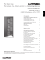
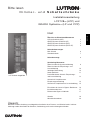
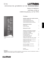
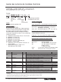
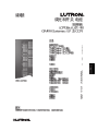
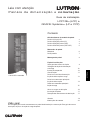
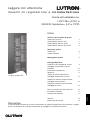
Installation Guide
LCP128TM (LCP) and
GRAFIK SystemsTM (LP and CCP)
D i m m i n g a n d S w i t c h i n g P a n e l s
Chinese
English Español Français
Português
NederlandsDeutsch
Italiano
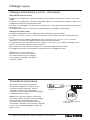
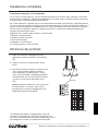
LCP Panel shown
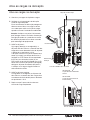
Overview
Use this guide to successfully install a dimming and switching panel. This guide describes panel installation,
wiring, and load activation.
®

®
2 Installation Guide for Dimming and Switching Panels
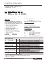
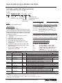
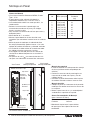
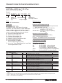
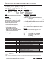
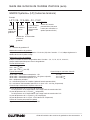
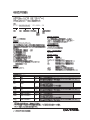
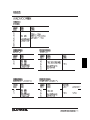
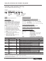
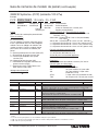
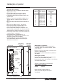
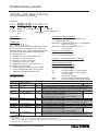
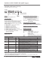
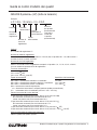
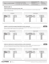
Panel Model Number Guide
LCP128TM (LCP) (120 V only)
See page 5 for 230 / 220–240 V
Modules:
Quantity and Type
Prefix
Example
L C P - 2 X 2 D 1 A 4 T - 1 2 0 4 M L - 2 0
Prefix
LCP = LCP dimming panel
Module Types
_X _S _D _Q _A _M _F _T
List modules in the order shown above. Insert the
quantity before each module code. Omit codes for
modules not used in panel. See table below for limits
on numbers of modules per panel.
X = Four-Circuit Switching (Relay) (XP)
S = One-Circuit Dimming (1U)
D = Two-Circuit Dimming (2U)
Q = Four-Circuit Dimming (4U)
A = Four-Circuit Adaptive Dimming (4A)
M = Four-Circuit Motor (4M)
F = Four-Circuit Quiet Fan Speed (4FSQ)
T = 0-10 V, DALI (broadcast), DSI, and PWM
Ballast Control (TVM)
Feed Voltage Feed Current
120 for 120 V 20 A or 175 A
Feed
Voltage
Branch Circuit
Breaker Rating
Feed
Type
Feed Type/Input Ratings
FT = Feed-through panel (circuit breakers not included)
/ 120 V
3M or 3ML = 1 phase 3 wire feed (split phase) /
120 / 240 V
4M or 4ML = 3 phase 4 wire feed / 120 / 208 V
Branch Circuit Breaker Rating
Omit for feed-through panels
20 for 20 A branch circuit breakers
Frequency - All Model Numbers and Voltages
50 / 60 Hz
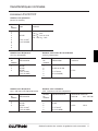
Output (Load) Ratings
Module Type Rating
XP 16 A per circuit
1U, 2U, 4U 16 A per module
4A 16 A per module, 10 A per output
4M 16 A per module, 5 A per output
(1/4 HP motor),
1 motor per output
4FSQ 2 A per output (single ceiling fan)
TVM 50 mA per channel, 750 mA per system
Module Quantity Limits
Panel Size Feed type TVM 4A 4U 4M
Mini Feed-through NA Any combination up to 3 modules
Mini Feed-through 0 to 4 Any combination up to 2 modules; must have 1 4U or XP module
minimum; each 4U or XP module can control only 2 TVM modules
Mini Breakers NA Any combination up to 3 modules
Mini Breakers 0 to 4 Any combination up to 2 modules;
must have 1 4U module minimum;
each 4U module can control only 2 TVM modules
Standard Feed-through NA Any combination up to 9 modules
Standard Feed-through 0 to 12 Any combination up to 8 modules; must have 1 4U or XP module
minimum; each 4U or XP module can control only 2 TVM modules
Standard Breakers (main lugs) NA Any combination up to 9 modules
Standard Breakers (main lugs) NA Any combination up to 7 modules
Standard Breakers (main lugs) 0 to 12 Any combination up to 7 modules;
must have 1 4U module minimum;
each 4U module can control only 2 TVM modules
Standard Breakers (main lugs) 0 to 12 Any combination up to 5 modules; must have 1 4U or XP module
minimum; each 4U or XP module can control only 2 TVM modules
Notes
• ConsultLutronforpanelswithcustombreakerneeds.
• TVM=0isaTVM-readypanel;TVMmodulescaneasilybeinstalledinthefuture.
• TVM=NAisnotTVM-ready
XP
0
0
0
0

®
Installation Guide for Dimming and Switching Panels 3
Example
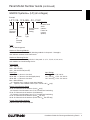
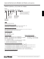
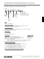
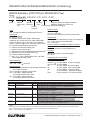
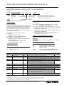
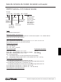
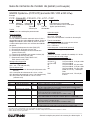
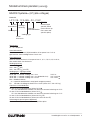
Panel Model Number Guide (continued)
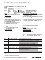
GRAFIK SystemsTM (LP) (all voltages)
Prefix
L P 7 / 2 8 - 1 2 0 4 M L - 2 0 - C G P _ _ _ _
Prefix
LP = LP dimming panel
Number of Dimming Modules
Indicates number of 4-circuit (4U) dimming modules in the panel: 1 through 8;
also indicates number of full load circuits
Number of Dimming Circuits
Indicates number of dimming circuits in the panel: 4, 8, 12, 16, 20, 24, 28, or 32;
each module has four dimming circuits
Feed Voltage
120 = 120 V
230 = 230 V (CE)
240 = 220 to 240 V (non-CE)
Feed Type Input Ratings
2M or 2ML = 1 phase 2 wire feed 120 V 175 A 50 / 60 Hz
3M or 3ML = 1 phase 3 wire feed (split phase) 120 / 240 V 175 A 50 / 60 Hz
4M or 4ML = 3 phase 4 wire feed 120 / 208 V 175 A 50 / 60 Hz
Mxx = Main Breaker;
xx = breaker size in amps (custom panel option)
IS = 3 phase 4 wire isolation switch (230 / 220 to 240 V only)
Branch Circuit Breaker Rating
20 for 20 A branch circuit breakers (120 V only)
20 A branch circuit breakers have a 16 A continuous load rating
15 for 15 A branch circuit breakers (120 V only)
15 A branch circuit breakers have a 12 A continuous load rating
13 for 13 A branch circuit breakers (230 V CE only)
16 for 16 A branch circuit breakers (220 to 240 V non-CE only)
Custom Panel Suffix (optional)
Indicates panel with special options
Number
of
Dimming
Circuits
Feed
Voltage
Feed
Type
Branch Circuit
Breaker
Rating
Number of
Dimming
Modules
Custom Panel
Suffix
(contact
Lutron for
custom
options)

®
4 Installation Guide for Dimming and Switching Panels
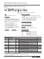
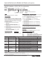
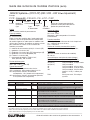
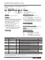
Panel Model Number Guide (continued)
Prefix
CCP = Custom combination panel
Module Types
_X _L _A _M _F _T
List modules in the order shown above. Insert
the quantity before each module code. Omit
codes for modules not used in panel. See table
below for limits on numbers of modules per
panel.
X = Four-Circuit Switching (Relay) (XP)
L = Four-Circuit Dimming (4U)
A = Four-Circuit Adaptive Dimming (4A)
M = Four-Circuit Motor (4M)
F = Four-Circuit Quiet Fan Speed (4FSQ)
T = 0-10 V, DALI (broadcast), DSI, and PWM
Ballast Control (TVM)
Feed Voltage Feed Current
120 for 120 V 15 A or 20 A or 175 A
GRAFIK SystemsTM (CCP) (120 V only)
Example
C C P - 2 X 2 L 1 A 4 T - 1 2 0 4 M L - 2 0 - C G P _ _ _
Module Quantity Limits
Panel Size Feed type TVM 4A 4U 4M
Mini Feed-through NA Any combination up to 3 modules
Mini Feed-through 0 to 4 Any combination up to 2 modules; must have 1 4U or XP module
minimum; each 4U or XP module can control only 2 TVM modules
Mini Breakers NA Any combination up to 3 modules
Mini Breakers 0 to 4 Any combination up to 2 modules;
must have 1 4U module minimum;
each 4U module can control only 2 TVM modules
Standard Feed-through NA Any combination up to 9 modules
Standard Feed-through 0 to 12 Any combination up to 8 modules; must have 1 4U or XP module
minimum; each 4U or XP module can control only 2 TVM modules
Standard Breakers (main lugs) NA Any combination up to 9 modules
Standard Breakers (main lugs) NA Any combination up to 7 modules
Standard Breakers (main lugs) 0 to 12 Any combination up to 8 modules;
must have 1 4U module minimum;
each 4U module can control only 2 TVM modules
Standard Breakers (main lugs) 0 to 12 Any combination up to 5 modules; must have 1 4U or XP module
minimum; each 4U or XP module can control only 2 TVM modules
Notes
• ConsultLutronforpanelswithcustombreakerneeds.
• TVM=0isaTVM-readypanel;TVMmodulescaneasilybeinstalledinthefuture.
• TVM=NAisnotTVM-ready
XP
0
0
0
0
Modules:
Quantity and Type
Prefix Feed
Voltage
Feed
Type
Custom
Panel Suffix
(contact Lutron for custom options)
Branch
Circuit
Breaker
Rating
Feed Type / Input Ratings
FT = Feed-through panel (circuit breakers not included) /
120 V
3M or 3ML = 1 phase 3 wire feed (split phase) / 120 / 240 V
4M or 4ML = 3 phase 4 wire feed / 120 / 208 V
2 = 1 phase 2 wire input breakers (mini only)
3 = 1 phase 3 wire input breakers (mini only)
4 = 3 phase 4 wire input breakers (mini only)
Branch Circuit Breaker Rating
20 = 20 A branch circuit breakers
15 = 15 A branch circuit breakers
Custom Panel Suffix (optional)
Indicates panel with special options
Frequency
(All Model Numbers and Voltages): 50 / 60 Hz
Output (Load) Ratings
Module Type Rating
XP, 4U 16 A per circuit
4A 16 A per module, 10 A per output
4M 16 A per module, 5 A per output
(1/4 HP motor)
4FSQ 2 A per output (single ceiling fan)
TVM 50 mA per channel, 750 mA per system

®
Installation Guide for Dimming and Switching Panels 5
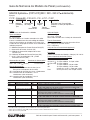
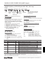
Panel Model Number Guide (continued)
Prefix
CCP = Custom combination panel
Module Types
_X _L _E _A _M _T
List modules in the order shown above. Insert the
quantity before each module code. Omit codes for
modules not used in panel. See table below for limits
on numbers of modules per panel.
X = Four-Circuit Switching (Relay) (XP)
L = Four-Circuit Dimming (4U)
E = Four-Circuit Electronic Low Voltage Dimming (4E)
A = Four-Circuit Adaptive Dimming (4A)
M = Four-Circuit Motor (4M)
T = 0-10 V, DALI (broadcast), DSI, and PWM
Ballast Control (TVM)
Feed Voltage Feed Current
230 = 230 V (CE) 10 A to 125 A
240 = 220 to 240 V (non-CE) 10 A to 125 A
Feed Type
FT = feed-through panel (circuit breakers not included)
4IS = 3 phase 4 wire isolation switch
2M = 1 phase 2 wire input breakers (mini only)
4M = 3 phase 4 wire input breakers (mini only)
GRAFIK SystemsTM (CCP/LCP) (230 / 220 to 240 V only)
Modules:
Quantity
and Type
Prefix
Example
C C P - 1 X 4 L 2 T - 2 3 0 4 I S - C E - L C P - C G P _ _ _
Feed
Voltage
Feed
Type
Custom
Panel Suffix
(contact Lutron for custom options)
Region
Suffix
Region Suffix
CE = 230 V
AU = 220 to 240 V
Note: Should match feed voltage
Controller Type
Omit for single-link circuit selector
2L = 2LinkTM circuit selector
LCP = LCP128TM
Custom Panel Suffix (optional)
Indicates panel with special options
Frequency
(All Model Numbers and Voltages)
50 / 60 Hz
Output (Load) Ratings
Module Type Rating
XP 16 A per circuit
4U (230 V ) 13 A per module, 10 A per output
4U (240 V ) 16 A per module
4A 13 A per module, 8 A per output
4E 16 A per module, 10 A per output
4M 16 A per module, 5 A per output
(1/4 HP motor), 1 motor per output
TVM 50 mA per channel, 750 mA per system
Controller
Type
Module Quantity Limits
Panel Size Feed type TVM 4A 4U 4E 4M
Mini Feed-through NA Any combination up to 3 modules
Mini Feed-through 0 to 4 Any combination up to 2 modules; must have 1 4U or XP module
minimum; each 4U or XP module can control only 2 TVM modules
Mini Input breakers NA Any combination up to 3 modules
Mini Input breakers 0 to 4 Any combination up to 2 modules;
must have 1 4U module minimum;
each 4U module can control only 2 TVM modules
Standard Feed to through 0 to 12 Any combination up to 8 modules; must have 1 4U or XP module
minimum; each 4U or XP module can control only 2 TVM modules
Standard Input breakers 0 to 12 Any combination up to 8 modules;
must have 1 4U module minimum;
each 4U module can control only 2 TVM modules
Standard Input breakers 0 to 12 Any combination up to 6 modules; must have 1 4U or XP module
minimum; each 4U or XP module can control only 2 TVM modules
Notes
• ConsultLutronforpanelswithcustombreakerneeds.
• TVM=0isaTVM-readypanel;TVMmodulescaneasilybeinstalledinthefuture.
• TVM=NAisnotTVM-ready
XP
0
0
0

®
6 Installation Guide for Dimming and Switching Panels
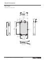
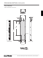
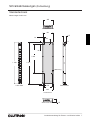
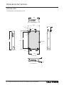
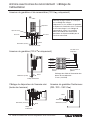
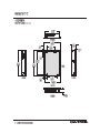
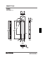
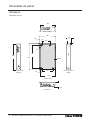
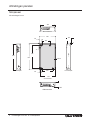
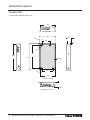
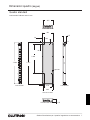
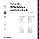
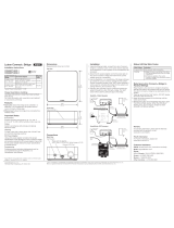
Panel Dimensions
Mini Panel
Bottom View
Top View
Right SideLeft Side
Dimensions are in inches (mm).
Front View
14.375
(365)
15.875
(403)
8.00
(203)
2.2
(56)
0.15
(4)
4.21
(107)
1.34
(34)
21.50
(546)
24.50
(622)
24.00
(610)
2.21
(56)
15.13
(384)
10.75
(273)
4.09
(104)
Cover

®
Installation Guide for Dimming and Switching Panels 7
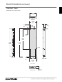
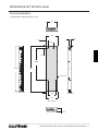
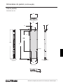
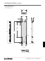
Panel Dimensions (continued)
Standard Panel
Bottom View
Top View
Right Side
Dimensions are in inches (mm).
Left Side
Front View
14.375
(365)
15.875
(403)
2.43
(62)
8.00
(203)
4.21
(107)
0.15
(4)
2.69
(68)
41.75
(1060)
59.50
(1511)
59.00
(1499)
2.43
(62)
11.00
(279)
15.125
(394)
4.15
(105)
Cover

®
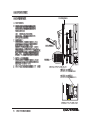
8 Installation Guide for Dimming and Switching Panels
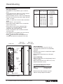
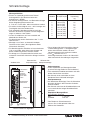
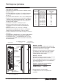
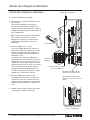
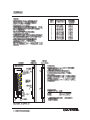
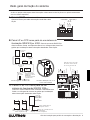
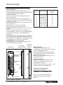
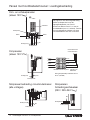
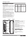
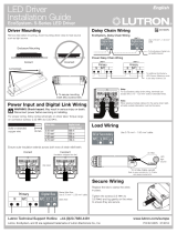
Panel Mounting
Mounting Guidelines
•ForIndoorUseOnly!NEMA,Type1enclosure,
IP20.
•Panelgeneratesheat.Mountonlywhereambient
temperature is 32 to 104 °F (0 to 40 °C).
•Relativehumiditymustbe<90%non-condensing.
•Reinforcewallstructureforpanelweightandlocal
codes; see table.
•Allow12in(305mm)clearanceaboveandbelow
panel.
•Mountwithin7°oftruevertical.
•Mountpanelwhereaudiblenoiseisacceptable.
(Internal relays click.)
•Mountpanelsoline(mains)voltagewiringis
at least 6 ft (1.8 m) from audio or electronic
equipment and associated wiring.
•Installinaccordancewithallnationalandlocal
electrical codes.
•This equipment is air-cooled. Vents must not be
blocked or you will void the warranty.
•230 V panels with 13 A circuit breakers are
intended for industrial or commercial use only.
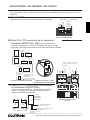
1
2
3
4
5
6
7
8
9
Max. Weight w/o
Packaging
Pounds (kg)
No.
Modules
Max. Heat
BTUs (Kcal)/Hr.
Surface Mounting
•Lutronrecommendsusing1/4in(6mm)
mounting bolts (maximum size accepted by
keyholes).
•Reinforcewallstructureasrequiredforweight
and local codes.
•Donotmountpaneldirectlytowallboard/
drywall.
Recess Mounting
•Mounttowallstudbyscrewingthroughslotsin
corners of panel.
•Mountpanelbetweenflushand1/8in(3mm)
below finished wall surface.
Side View:
Surface Mount
Side View:
Recess Mount
Front View
Recommended Mounting Heights*
(for LCP128TM systems)
Mini 45 in (1143 mm)
Standard 25 in (635 mm)
* Measure from floor to bottom of panel;
optimal viewing height for controller.
1
2
4
3
5
6
8
7
A
B
C
N
Load circuit wiring
Feed wiring
Do not
obstruct
vents!
PELV
(Class 2: USA)
Wiring
Air flow
Air flow
Low-voltage
control
wiring for
TVM loads
90 (22.68)
170 (42.84)
250 (63.00)
330 (83.16)
410 (103.32)
490 (123.48)
570 (143.64)
650 (163.80)
730 (183.96)
24 (11)
35 (16)
37 (17)
68 (25)
71 (26)
74 (27)
77 (28)
80 (29)
83 (30)
LP8/32-1204ML-20 shown

®
Installation Guide for Dimming and Switching Panels 9
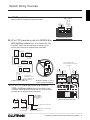
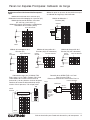
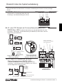
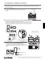
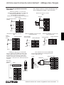
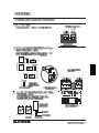
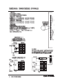
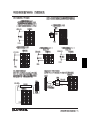
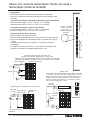
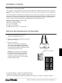
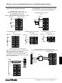
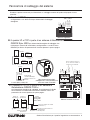
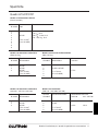
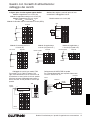
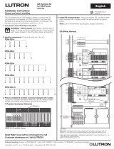
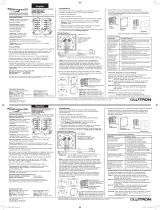
System Wiring Overview
A. LCP128TM panel: Refer to the LCP128 Setup and
Operation Manual for detailed wiring information.
B. LP or CCP panel as a part of a GRAFIK Eye®
4000 lighting system: Refer to the GRAFIK Eye 4000
Installation, Setup, and Operation Manual and the system
overview pictured here for detailed wiring information.
C. LP or CCP panel as a part of a GRAFIK
7000TM lighting system: Refer to the GRAFIK 7000
Installation, and Maintenance Guide and the system overview
pictured here for detailed wiring information.
1 2 3 4 D 5 1 2 3 4
Contact closure input
(CCI) 1
Contact closure input
(CCI) 2
Common
Signal
Common
Signal
Common
+24 V
MUX
MUX
Drain
Sense
{
{
Controller Terminals
SELECT CIRCUIT
2
1
Circuit
Data A OK
Power
1 2 3 4 5D
Common
24VFW
MUX
MUX
Drain
Sense
1 2 3 4
D
5
B
Comm
Drain
MUX
MUX
C
D
Link
A
Link
C
D
Data B OK
Common
MUX
MUX
Drain
Note: Single-link circuit
selectors will not have Link B
connector.
Common
+24 V
MUX
MUX
Drain
Sense
Circuit Selector Terminals
Incorrect: Branch, T-tap, or
home run not acceptable
Panel
Panel
To other panels,
GRAFIK Eye control
units, wallstations, or
control interfaces
Control
interface
GRAFIK
Eye
GRAFIK
Eye
Wallstation
Correct: Daisy chain OK
GRAFIK
Eye
Control
interface
Wallstation
GRAFIK 5000TM,
GRAFIK 6000®, or
GRAFIK 7000TM
panel
Power panel link
Control station device link
Lighting zone controller link
Integration to other devices
Power
panel
Power
panel

®
10 Installation Guide for Dimming and Switching Panels
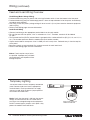
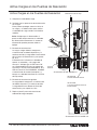
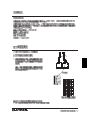
Wiring (continued)
Feed Wiring (Mains Voltage Wiring)
•Preferredfeedwiringentryforpanelswithmainlugs/isolationswitchisfromthebottomleftofthepanel.
•Preferredfeedwiringentryforfeed-throughpanelsisfromthetoporbottomleftofthepanel,wireddirectly
to module terminal blocks.
•Runwiringsothatline(mains)voltagewiringwillbeatleast6ft(1.8m)fromsoundorelectronicequipment
and its wiring.
•RefertoFeedWiringpagesformoreinformation.
Load Circuit Wiring
•Connectloadwiringtotheappropriateterminalblocksetforeachmodule.
•For230V and 240 V panels, “Hot” is referred to as “Live”. Therefore, terminals will be labeled
DL and L.
•TheDimmedHot/Live(DH/DL)terminalblockisgroupedwithanumberedHot/Live(H/L)(H1,H2,etc./L1,L2,
etc.). The number represents both the module and circuit breaker number.
•Outputterminalblocksacceptone14to10AWG(2.5to4.0mm
2
) wires. Preferred entry is from the top left
of the panel.
•Common neutrals are not permitted. Run separate neutrals for each load circuit.
•RefertoLoadWiringpagesformoreinformation.
Notice: Panels require entry of wires
as specified. Improper entry will block
serviceable parts and impede air flow
through the panel.
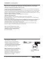
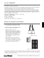
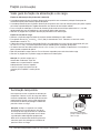
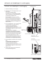
Feed and Load Wiring Overview
You do not need to install a temporary distribution
panel. Connect load wires into the appropriate
terminal blocks. Each input breaker can supply
power to a load while the bypass jumper protects
the module from load faults.
Input circuit breaker
Bypass jumper protects the
module from load faults.
Notice: Verify that the panel is fed from the correct
voltage. A feed miswire or loss of a feed neutral
can cause over-voltage damage to the equipment.
Do NOT remove bypass jumpers at this point—they
protect the modules from load faults.
Temporary Lighting

®
Installation Guide for Dimming and Switching Panels 11
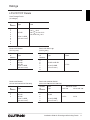
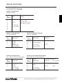
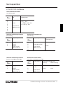
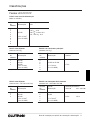
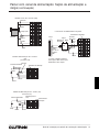
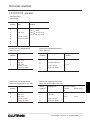
Ratings
Number
of
Modules
Feed
Type
Max.
Feed
1
2
3
4
5
6
7
8
9
1Ø 2W
14 to 10 AWG
(2.5 to 4.0 mm
2
)
120 V : 20 A
230 V : 13 A or 16 A
220 to 240 V : 16 A
LP/LCP/CCP Panels
Panels with Breaker
(120 V only)
Number
of
Modules
Feed
Type
1
2
3
1Ø 2W
1Ø 3W
3Ø, 4W
14 to 10 AWG
(2.5 to 4.0 mm
2
)
Panels with Main Lugs
(120 V only)
Number
of
Modules
Feed
Type
Maximum
Feed
4
5
6
7
8
9
1Ø 3W or 3Ø 4W
14 to 2/0 AWG
(2.5 to 70 mm
2
)
175 A
Panels with Breaker
(220 to 240 V and 230 V only)
Number
of
Modules
Feed
Type
1
2
3
1Ø 2W
1Ø 2W
3Ø 4W
14 to 10 AWG
(2.5 to 4.0 mm
2
)
Panels with Isolation Switch
(220 to 240 V and 230 V only)
Number
of
Modules
Feed
Type
Maximum Feed
230 V 220 to 240 V
4
5
6
7
8
3Ø 4W
14 to 2/0 AWG
(2.5 to 70 mm
2
)
125 A 125 A
Feed-Through Panels
(all voltages)

®
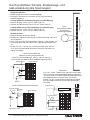
12 Installation Guide for Dimming and Switching Panels
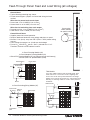
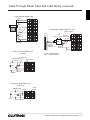
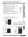
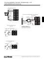
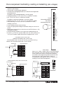
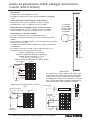
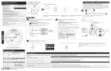
Feed-Through Panel: Feed and Load Wiring (all voltages)
N
H1
SH1
H2
SH2
H3
SH3
H4
SH4
To distribution
panel
Load
Hot/live
Switched
hot/live
4-Circuit Switching (Relay) Module (XP)
Bypass jumper
Feed
N
N
DH
H
DH
N
DH
DH
N
N
Dimmed hot/live
Hot/Live
Neutral
Neutral
Load
4-Circuit Dimming Module (4U)
4-Circuit Adaptive Dimming Module (4A)
4-Circuit ELV Dimming Module (4E: 230 V and 220 to 240 V only)
4-Circuit Quiet Fan Speed Module (4FSQ)
Bypass jumper
Feed
General Notes
•Typicaldimming/switchinglegsshown.
•Donotremovebypassjumpersuntilafterloadwiringhasbeen
verified.
Wire sizes for power feed, to each input
•Powerfeed:14to10AWG(2.5to4.0mm
2
)
•Neutralfeed:14to10AWG(2.5to4.0mm
2
)
Wire sizes for load wiring, from each output
•Dimmedhot(live):14to10AWG(2.5to4.0mm
2
)
•Loadneutral:14to10AWG(2.5to4.0mm
2
)
Control Circuit Power
•Suppliespowerforinternaloperation.
•Requiresdedicatedfeedwithsamevoltageandphaseaspanel.
•Mustbe1/4in(6mm)awayfromPELV(Class2:USA)controlwiring
harness.
•Panelvoltage(seepages2to3)indicatesfeedvoltage.
•For230V and 240 V panels, “Hot” is referred to as “Live”.
Therefore, terminals will be labeled L and DL.
See terminal
block modules
for specific wiring
details.
Bypass jumper
Feed
Neutral
Hot/Live
TVM Module
For 0-10 V, PWM, Tridonic® DSI, and DALI loads. Each
TVM controls two consecutive circuits of lighting and
are the first circuits in the panel. Maximum low-voltage
ballastcontrolcurrent:50mAperzone,750mAperpanel.
Dimming or switching module is used to switch power to
the ballast.
+ 1 –
+ 2 –
N
H/L
+
–
N
N
DH
H
DH
N
DH
DH
N
N
Ballast
Neutral
Dimmed hot/live
TVM
Circuit breaker
Circuit breaker
Circuit breaker
Neutral

®
Installation Guide for Dimming and Switching Panels 13
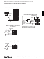
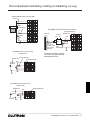
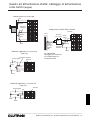
Feed-Through Panel: Feed and Load Wiring (continued)
Bypass jumper
N
N
DH
H
Dimmed hot/live
Neutral
Load
1-Circuit Dimming Module (1U)
(LCP only)
Bypass
jumper
Hot/Live
Feed
Neutral
N
N
DH
H
DH
N
Feed
Dimmed hot/live
Neutral
Load
2-Circuit Dimming Module (2U)
(LCP only)
Bypass jumper
Neutral
Hot/Live
N
N
L
H
R
N
L
R
N
N
L
R
L
R
Lower
Neutral
Hot/Live
Neutral
4-Circuit Motor Module (4M)
Feed
Raise
Hot/Live
Feed
Neutral
Neutral
Hot/
Live
N
N
DH
H
DH
N
DH
DH
N
N
Connecting an NGRX-FDBI to a Panel
Load
Lutron®
Eco-10® or
Hi-lume®
FDB ballast
Dimmed
hot/live
Lutron®
FDBI
Feed
Refer to FDBI Installation
Sheet for detailed wiring.
Circuit breaker
Circuit
breaker
Circuit breaker

®
14 Installation Guide for Dimming and Switching Panels
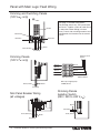
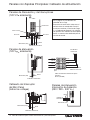
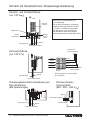
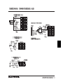
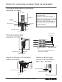
Panel with Main Lugs: Feed Wiring
Neutral
Power (hot/live)
Feed wiring
Prewired to circuit
breakers
Prewired neutral to
dimming modules
Phase A
N
Main lugs in panel
Phase B
Phase C
Phase A
N
Phase B
Phase C
Neutral
Neutral bus
Neutral bus
Power (hot/live)
Feed wiring
Dimming and Switching Panels
(120 V only)
Dimming Panels
(120 V only)
Ground bar
Breakers
N
Feed wiring
Notes
•See page 15 for load wiring details.
• On dimming panels only, the input breaker
of Circuit 1 supplies current to Load Circuit
1 and to the Control Wiring (2 A draw
max.). Panels with switching modules have
a dedicated circuit breaker for the control
circuit.
Neutral
Power (hot/live)
Main Lugs feed wiring gauge:
2/0 AWG (70 mm
2
)
Mini Panel Breaker Wiring
(all voltages)
Feed wiring
Neutral
Power (hot/live)
Dimming Panels
Isolation Switch
(230 / 220 to 240 V )

®
Installation Guide for Dimming and Switching Panels 15
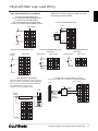
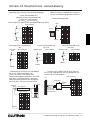
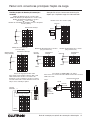
Panel with Main Lugs: Load Wiring
N
N
DH
H
N
N
DH
H
DH
N
N
N
DH
H
DH
N
DH
DH
N
N
N
N
L
H
R
N
L
R
N
N
L
R
L
R
H
N
H1
SH1
H2
SH2
H3
SH3
H4
SH4
Raise
Lower
Neutral
4-Circuit Motor Module (4M)
N
N
DH
H
N
N
DH
H
DH
N
N
N
DH
H
DH
N
DH
DH
N
N
N
N
L
H
R
N
L
R
N
N
L
R
L
R
H
N
H1
SH1
H2
SH2
H3
SH3
H4
SH4
Dimmed hot/live
Neutral
Load
1-Circuit Dimming Module (1U)
(LCP only)
Bypass jumper
N
N
DH
H
N
N
DH
H
DH
N
N
N
DH
H
DH
N
DH
DH
N
N
N
N
L
H
R
N
L
R
N
N
L
R
L
R
H
N
H1
SH1
H2
SH2
H3
SH3
H4
SH4
Dimmed hot/live
Neutral
Load
2-Circuit Dimming Module (2U)
(LCP only)
Bypass jumper
N
N
DH
H
N
N
DH
H
DH
N
N
N
DH
H
DH
N
DH
DH
N
N
N
N
L
H
R
N
L
R
N
N
L
R
L
R
H
N
H1
SH1
H2
SH2
H3
SH3
H4
SH4
Dimmed hot/live
Neutral
Load
4-Circuit Dimming Module (4U)
4-Circuit Adaptive Dimming Module (4A)
4-Circuit ELV Dimming Module
(4E: 230 V and 220 to 240 V only)
4-Circuit Fan Speed Control Module (4FSQ)
Bypass jumper
N
N
DH
H
N
N
DH
H
DH
N
N
N
DH
H
DH
N
DH
DH
N
N
N
N
L
H
R
N
L
R
N
N
L
R
L
R
H
N
H1
SH1
H2
SH2
H3
SH3
H4
SH4
Neutral
Load
Switched
hot/live
4-Circuit Switching Module (XP)
Bypass jumper
Notice: Do not remove bypass jumpers until after
load wiring has been verified.
Typical Dimming/Switching Leg Shown
Load Wiring for TVM Module
For 0-10 V, PWM, and Tridonic® DSI loads. Each
TVM controls two consecutive circuits of lighting
and are the first circuits in the panel. Maximum
low-voltage ballast control current:
50mAperzone,750mAperpanel.
+ 1 –
+ 2 –
N
H/L
+
–
N
N
DH
H
DH
N
DH
DH
N
N
Ballast
Neutral
Dimmed
hot/live
TVM
Bypass jumper
N
N
DH
H
DH
N
DH
DH
N
N
Connecting an NGRX-FDBI to a Panel
For Hi-lume® FDB or Eco-10® Fluorescent Dimming Ballast
Load
Lutron®
Eco-10 or
Hi-lume
FDB ballast
Neutral
Dimmed
hot/live
Lutron®
FDBI
Feed
Bypass jumper
Shade

®
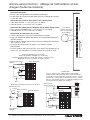
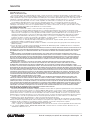
16 Installation Guide for Dimming and Switching Panels
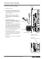
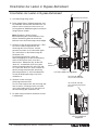
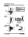
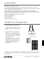
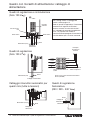
Activate Loads in Bypass
DH
DH
H
N
N
N
N
N
DH
DH
H
1
2
N
A. Complete load wiring.
B. Check that the bypass jumpers are in place.
These jumpers protect from load faults and
must be used to check load wiring when it is
installed or modified.
Notice: Verify that the panel is fed from
the correct voltage. A feed miswire or loss
of a feed neutral can cause damage to the
equipment.
C. Turn circuit breaker 1 ON.
The load(s) should energize, the breaker
should not trip, and total load current must be
within the circuit breaker’s limit and less than
or equivalent to 16 A.
Circuit breaker 1 powers the control wiring as
well as Circuit 1’s dimmer and load(s). Check
that the Power OK LED on the Controller
(LCP128TM) or circuit selector (LP or CCP) is
ON. If the Power OK LED is OFF, turn OFF the
control circuit breaker (breaker 1) and check
for a miswire on the low voltage link.
D. Turn next circuit breaker ON.
The load should energize, the breaker should
not trip, and total load current must be within
the circuit breaker’s limit and less than or
equal to 16 A.
E. Repeat step D for each circuit with completed
load wiring.
AC RMS current
Bypass jumper
Load circuit wiring
‘Power OK’ LED
at the bottom of LCP128 Controller
‘Power OK’ LED
at the top of LP/CCP Circuit Selector
Activate Loads in Bypass
LCP-8D-1204ML-20 shown
LP3/12-1204ML-20 shown

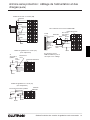
®
Installation Guide for Dimming and Switching Panels 17
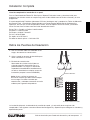
A. After all load wiring has been checked, turn
circuit breakers OFF.
B. Remove and store the bypass jumpers for
possible future use.
C. Turn circuit breakers ON.
All circuits are now set to the default Non-Dim
load type. Non-Dim load types will respond
by immediately going to full ON in any lighting
scene (except the OFF scene).
Notice: Reuse the bypass jumpers whenever
work is being done on a load. Damage caused
by short-circuits and miswiring is not covered
by the product warranty.
Panel installation, control station wiring, and load activation are now complete.
Next Step: Refer to the Setup and Operation Manual to set up the functions and operation of the panel.
DH
DH
DH
DH
H
N
N
N
N
N
Bypass jumper
Module with 4 outputs shown
Complete Installation
Remove Bypass Jumpers
You have completed your panel installation.
For Onsite Factory Commissioning, call Lutron Technical Support and select Startup to schedule a field
service visit. Allow for 10 working days between day of call and scheduled visit.
If you purchased Telephone Startup (LCP128TM only), stop here and complete the Control Location, Panel,
and Control Station Tables that are located in the back of the Setup and Operation Manual. Once the tables
are complete, call Lutron Technical Support and select Startup. Please call 24 hours prior to desired system
startup.
In the U.S., Canada, and the Caribbean: 1.800.523.9466
In Mexico: +1.888.235.2910
In Europe: +44.(0)20.7702.0657
In Asia: +65.6220.4666
In Japan: +81.3.5575.8411
In all other countries: +1.610.282.6701

®
18 Installation Guide for Dimming and Switching Panels
Notes

®
Installation Guide for Dimming and Switching Panels 19
Warranty
Lutron Electronics Co., Inc.
One Year Limited Warranty
For a period of one year from the date of purchase, and subject to the exclusions and restrictions described below, Lutron
warrants each new unit to be free from manufacturing defects. Lutron will, at its option, either repair the defective unit or
issue a credit equal to the purchase price of the defective unit to the Customer against the purchase price of comparable
replacement part purchased from Lutron. Replacements for the unit provided by Lutron or, at its sole discretion, an approved
vendor may be new, used, repaired, reconditioned, and/or made by a different manufacturer.
If the unit is commissioned by Lutron or a Lutron approved third party as part of a Lutron commissioned lighting control
system, the term of this warranty will be extended, and any credits against the cost of replacement parts will be prorated, in
accordance with the warranty issued with the commissioned system, except that the term of the unit’s warranty term will be
measured from the date of its commissioning.
EXCLUSIONS AND RESTRICTIONS
This Warranty does not cover, and Lutron and its suppliers are not responsible for:
1. Damage, malfunction or inoperability diagnosed by Lutron or a Lutron approved third party as caused by normal wear
and tear, abuse, misuse, incorrect installation, neglect, accident, interference or environmental factors, such as (a) use of
incorrect line voltages, fuses or circuit breakers; (b) failure to install, maintain and operate the unit pursuant to the operating
instructions provided by Lutron and the applicable provisions of the National Electrical Code and of the Safety Standards
of Underwriter’s Laboratories; (c) use of incompatible devices or accessories; (d) improper or insufficient ventilation;
(e) unauthorized repairs or adjustments; (f) vandalism; or (g) an act of God, such as fire, lightning, flooding, tornado,
earthquake, hurricane or other problems beyond Lutron’s control.
2. On-site labor costs to diagnose issues with, and to remove, repair, replace, adjust, reinstall and/or reprogram the unit or any
of its components.
3. Equipment and parts external to the unit, including those sold or supplied by Lutron (which may be covered by a separate
warranty).
4. The cost of repairing or replacing other property that is damaged when the unit does not work properly, even if the damage
was caused by the unit.
EXCEPT AS EXPRESSLY PROVIDED IN THIS WARRANTY, THERE ARE NO EXPRESS OR IMPLIED WARRANTIES OF
ANY TYPE, INCLUDING ANY IMPLIED WARRANTIES OF FITNESS FOR A PARTICULAR PURPOSE OR MERCHANTABILITY.
LUTRON DOES NOT WARRANT THAT THE UNIT WILL OPERATE WITHOUT INTERRUPTION OR BE ERROR FREE.
NO LUTRON AGENT, EMPLOYEE OR REPRESENTATIVE HAS ANY AUTHORITY TO BIND LUTRON TO ANY
AFFIRMATION, REPRESENTATION OR WARRANTY CONCERNING THE UNIT. UNLESS AN AFFIRMATION,
REPRESENTATION OR WARRANTY MADE BY AN AGENT, EMPLOYEE OR REPRESENTATIVE IS SPECIFICALLY INCLUDED
HEREIN, OR IN STANDARD PRINTED MATERIALS PROVIDED BY LUTRON, IT DOES NOT FORM A PART OF THE BASIS OF
ANY BARGAIN BETWEEN LUTRON AND CUSTOMER AND WILL NOT IN ANY WAY BE ENFORCEABLE BY CUSTOMER.
IN NO EVENT WILL LUTRON OR ANY OTHER PARTY BE LIABLE FOR EXEMPLARY, CONSEQUENTIAL, INCIDENTAL
OR SPECIAL DAMAGES (INCLUDING, BUT NOT LIMITED TO, DAMAGES FOR LOSS OF PROFITS, CONFIDENTIAL OR
OTHER INFORMATION, OR PRIVACY; BUSINESS INTERRUPTION; PERSONAL INJURY; FAILURE TO MEET ANY DUTY,
INCLUDING OF GOOD FAITH OR OF REASONABLE CARE; NEGLIGENCE, OR ANY OTHER PECUNIARY OR OTHER
LOSS WHATSOEVER), NOR FOR ANY REPAIR WORK UNDERTAKEN WITHOUT LUTRON’S WRITTEN CONSENT ARISING
OUT OF OR IN ANY WAY RELATED TO THE INSTALLATION, DEINSTALLATION, USE OF OR INABILITY TO USE THE
UNIT OR OTHERWISE UNDER OR IN CONNECTION WITH ANY PROVISION OF THIS WARRANTY, OR ANY AGREEMENT
INCORPORATING THIS WARRANTY, EVEN IN THE EVENT OF THE FAULT, TORT (INCLUDING NEGLIGENCE), STRICT
LIABILITY, BREACH OF CONTRACT OR BREACH OF WARRANTY OF LUTRON OR ANY SUPPLIER, AND EVEN IF LUTRON
OR ANY OTHER PARTY WAS ADVISED OF THE POSSIBILITY OF SUCH DAMAGES.
NOTWITHSTANDING ANY DAMAGES THAT CUSTOMER MIGHT INCUR FOR ANY REASON WHATSOEVER (INCLUDING,
WITHOUT LIMITATION, ALL DIRECT DAMAGES AND ALL DAMAGES LISTED ABOVE), THE ENTIRE LIABILITY OF
LUTRON AND OF ALL OTHER PARTIES UNDER THIS WARRANTY ON ANY CLAIM FOR DAMAGES ARISING OUT OF
OR IN CONNECTION WITH THE MANUFACTURE, SALE, INSTALLATION, DELIVERY, USE, REPAIR, OR REPLACEMENT
OF THE UNIT, OR ANY AGREEMENT INCORPORATING THIS WARRANTY, AND CUSTOMER’S SOLE REMEDY FOR THE
FOREGOING, WILL BE LIMITED TO THE AMOUNT PAID TO LUTRON BY CUSTOMER FOR THE UNIT. THE FOREGOING
LIMITATIONS, EXCLUSIONS AND DISCLAIMERS WILL APPLY TO THE MAXIMUM EXTENT ALLOWED BY APPLICABLE LAW,
EVEN IF ANY REMEDY FAILS ITS ESSENTIAL PURPOSE.
TO MAKE A WARRANTY CLAIM
To make a warranty claim, promptly notify Lutron within the warranty period described above by calling the Lutron Technical
Support Center at (800) 523-9466. Lutron, in its sole discretion, will determine what action, if any, is required under this
warranty. To better enable Lutron to address a warranty claim, have the unit’s serial and model numbers available when
making the call. If Lutron, in its sole discretion, determines that an on-site visit or other remedial action is necessary, Lutron
may send a Lutron Services Co. representative or coordinate the dispatch of a representative from a Lutron approved vendor
to Customer’s site, and/or coordinate a warranty service call between Customer and a Lutron approved vendor.
This warranty gives you specific legal rights, and you may also have other rights which vary from state to state. Some
states do not allow limitations on how long an implied warranty lasts, so the above limitation may not apply to you. Some
states do not allow the exclusion or limitation of incidental or consequential damages, so the above limitation or exclusion may
not apply to you.
Tridonic is a registered trademark of Zumtobel Aktiengesellschaft.
Lutron, the sunburst logo, GRAFIK Eye, GRAFIK 6000, Eco-10, and Hi-lume are reg is tered trademarks, and LCP128,
GRAFIK Systems, GRAFIK 5000, GRAFIK 7000, and 2Link are trademarks of Lutron Electronics Co., Inc.
© 2010 Lutron Electronics Co., Inc.

Contact Information
®
Lutron Electronics Co., Inc.
Made and printed in U.S.A.
P/N 032-342 Rev. A 12.15.10
Internet: www.lutron.com
E-mail: [email protected]
WORLD HEADQUARTERS
USA
Lutron Electronics Co., Inc.
7200 Suter Road, Coopersburg, PA 18036-1299
TEL +1.610.282.3800
FAX +1.610.282.1243
Toll-Free 1.888.LUTRON1
Technical Support 1.800.523.9466
North and South America Technical Hotlines
USA, Canada, Caribbean: 1.800.523.9466
Mexico: +1.888.235.2910
Central/South America: +1.610.282.6701
EUROPEAN HEADQUARTERS
United Kingdom
Lutron EA Ltd.
6 Sovereign Close, London, E1W 3JF United Kingdom
TEL +44.(0)20.7702.0657
FAX +44.(0)20.7480.6899
FREEPHONE (UK) 0800.282.107
Technical support +44.(0)20.7680.4481
ASIAN HEADQUARTERS
Singapore
Lutron GL Ltd.
15 Hoe Chiang Road, #07-03 Tower 15, Singapore 089316
TEL +65.6220.4666
FAX +65.6220.4333
Technical support +800.120.4491
Asia Technical Hotlines
Northern China: 10.800.712.1536
Southern China: 10.800.120.1536
Hong Kong: 800.901.849
Japan: +81.3.5575.8411
Macau: 0800.401
Singapore: 800.120.4491
Taiwan: 00.801.137.737
Thailand: 001.800.120.665853
Other countries: +65.6220.4666
Seite laden ...
Seite laden ...
Seite laden ...
Seite laden ...
Seite laden ...
Seite laden ...
Seite laden ...
Seite laden ...
Seite laden ...
Seite laden ...
Seite laden ...
Seite laden ...
Seite laden ...
Seite laden ...
Seite laden ...
Seite laden ...
Seite laden ...
Seite laden ...
Seite laden ...
Seite laden ...
Seite laden ...
Seite laden ...
Seite laden ...
Seite laden ...
Seite laden ...
Seite laden ...
Seite laden ...
Seite laden ...
Seite laden ...
Seite laden ...
Seite laden ...
Seite laden ...
Seite laden ...
Seite laden ...
Seite laden ...
Seite laden ...
Seite laden ...
Seite laden ...
Seite laden ...
Seite laden ...
Seite laden ...
Seite laden ...
Seite laden ...
Seite laden ...
Seite laden ...
Seite laden ...
Seite laden ...
Seite laden ...
Seite laden ...
Seite laden ...
Seite laden ...
Seite laden ...
Seite laden ...
Seite laden ...
Seite laden ...
Seite laden ...
Seite laden ...
Seite laden ...
Seite laden ...
Seite laden ...
Seite laden ...
Seite laden ...
Seite laden ...
Seite laden ...
Seite laden ...
Seite laden ...
Seite laden ...
Seite laden ...
Seite laden ...
Seite laden ...
Seite laden ...
Seite laden ...
Seite laden ...
Seite laden ...
Seite laden ...
Seite laden ...
Seite laden ...
Seite laden ...
Seite laden ...
Seite laden ...
Seite laden ...
Seite laden ...
Seite laden ...
Seite laden ...
Seite laden ...
Seite laden ...
Seite laden ...
Seite laden ...
Seite laden ...
Seite laden ...
Seite laden ...
Seite laden ...
Seite laden ...
Seite laden ...
Seite laden ...
Seite laden ...
Seite laden ...
Seite laden ...
Seite laden ...
Seite laden ...
Seite laden ...
Seite laden ...
Seite laden ...
Seite laden ...
Seite laden ...
Seite laden ...
Seite laden ...
Seite laden ...
Seite laden ...
Seite laden ...
Seite laden ...
Seite laden ...
Seite laden ...
Seite laden ...
Seite laden ...
Seite laden ...
Seite laden ...
Seite laden ...
Seite laden ...
Seite laden ...
Seite laden ...
Seite laden ...
Seite laden ...
Seite laden ...
Seite laden ...
Seite laden ...
Seite laden ...
Seite laden ...
Seite laden ...
Seite laden ...
Seite laden ...
Seite laden ...
Seite laden ...
Seite laden ...
Seite laden ...
Seite laden ...
Seite laden ...
Seite laden ...
Seite laden ...
Seite laden ...
-
 1
1
-
 2
2
-
 3
3
-
 4
4
-
 5
5
-
 6
6
-
 7
7
-
 8
8
-
 9
9
-
 10
10
-
 11
11
-
 12
12
-
 13
13
-
 14
14
-
 15
15
-
 16
16
-
 17
17
-
 18
18
-
 19
19
-
 20
20
-
 21
21
-
 22
22
-
 23
23
-
 24
24
-
 25
25
-
 26
26
-
 27
27
-
 28
28
-
 29
29
-
 30
30
-
 31
31
-
 32
32
-
 33
33
-
 34
34
-
 35
35
-
 36
36
-
 37
37
-
 38
38
-
 39
39
-
 40
40
-
 41
41
-
 42
42
-
 43
43
-
 44
44
-
 45
45
-
 46
46
-
 47
47
-
 48
48
-
 49
49
-
 50
50
-
 51
51
-
 52
52
-
 53
53
-
 54
54
-
 55
55
-
 56
56
-
 57
57
-
 58
58
-
 59
59
-
 60
60
-
 61
61
-
 62
62
-
 63
63
-
 64
64
-
 65
65
-
 66
66
-
 67
67
-
 68
68
-
 69
69
-
 70
70
-
 71
71
-
 72
72
-
 73
73
-
 74
74
-
 75
75
-
 76
76
-
 77
77
-
 78
78
-
 79
79
-
 80
80
-
 81
81
-
 82
82
-
 83
83
-
 84
84
-
 85
85
-
 86
86
-
 87
87
-
 88
88
-
 89
89
-
 90
90
-
 91
91
-
 92
92
-
 93
93
-
 94
94
-
 95
95
-
 96
96
-
 97
97
-
 98
98
-
 99
99
-
 100
100
-
 101
101
-
 102
102
-
 103
103
-
 104
104
-
 105
105
-
 106
106
-
 107
107
-
 108
108
-
 109
109
-
 110
110
-
 111
111
-
 112
112
-
 113
113
-
 114
114
-
 115
115
-
 116
116
-
 117
117
-
 118
118
-
 119
119
-
 120
120
-
 121
121
-
 122
122
-
 123
123
-
 124
124
-
 125
125
-
 126
126
-
 127
127
-
 128
128
-
 129
129
-
 130
130
-
 131
131
-
 132
132
-
 133
133
-
 134
134
-
 135
135
-
 136
136
-
 137
137
-
 138
138
-
 139
139
-
 140
140
-
 141
141
-
 142
142
-
 143
143
-
 144
144
-
 145
145
-
 146
146
-
 147
147
-
 148
148
-
 149
149
-
 150
150
-
 151
151
-
 152
152
-
 153
153
-
 154
154
-
 155
155
-
 156
156
-
 157
157
-
 158
158
-
 159
159
-
 160
160


Lutron Electronics LCP128 Installationsanleitung
- Typ
- Installationsanleitung
in anderen Sprachen
- English: Lutron Electronics LCP128 Installation guide
- français: Lutron Electronics LCP128 Guide d'installation
- español: Lutron Electronics LCP128 Guía de instalación
- italiano: Lutron Electronics LCP128 Guida d'installazione
- Nederlands: Lutron Electronics LCP128 Installatie gids
- português: Lutron Electronics LCP128 Guia de instalação
Verwandte Papiere
-
Lutron Electronics QSGR-6D Quick Installation And Operation Manual
-
 Lutron Electronics PALLADIOM WIN-BC-LWC Series Benutzerhandbuch
-
 Lutron Electronics SO-2BO Installationsanleitung
-
Lutron Electronics Grafik 5000 Installation Instructions Manual
-
 Lutron Electronics EcoSystem 5-Series Installationsanleitung
-
 Lutron Electronics PDW-QS Series Installationsanleitung
-
 Lutron Electronics seeTouch QSWS2-3BRLIR Installationsanleitung
-
 Lutron Electronics CONNECT-BDG-2 Installation Instructions Manual
-
 Lutron Electronics Homeworks QS seeTouch HQWIS-NB-NONE Installationsanleitung
-
 Lutron Electronics PowPak RMKS-DAL4-SZ Installation Instructions Manual


Sonstige Unterlagen
-
 Tridonic BasicDIM ILD 16DPI 69f Installationsanleitung
-
Emerson MITX-430 Benutzerhandbuch
-
CAME 67600740 Installationsanleitung
-
Yamaha PM4000 Benutzerhandbuch
-
Peavey IA 400 Power Amplifier Benutzerhandbuch
-
Hitachi CP2896TAN Benutzerhandbuch
-
-
-
Hikvision UD20201B-A Benutzerhandbuch
-
Lutron GRX-TVI Benutzerhandbuch
