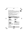
ABB RVC Installation And Operating Instructions Manual
- Typ
- Installation And Operating Instructions Manual

Power Factor Controller
RVC
Installation and operating
instructions
Régulateur de facteur de
puissance RVC
Instructions d’installation et
d’utilisation
Regolatori del fattore di
potenza RVC
Istruzioni di installazione e
funzionamento
Reguladores del factor de
potencia RVC
Instrucciones de instalación y
de funcionamiento
Controlador de Fator de
Potência RVC
Instalação e instruções de
operação
Blindleistungsregler RVC
Installations- und
Bedienungsanleitung
Cos ϕ -regelaars type RVC
Installatie- en
gebruiksaanwijzing
Reaktiv effektregulator
RVC
Installations- och
användarhandbok
Loistehonsäätimet RVC
Asennus- ja käyttöohjeet
Güç Faktörü Kontrol
Cihaz› RVC
Kurma ve Çal›st›rma
Yönergeleri
Qthlirsy Rtmsekers
Irvoy RVC
Odgey Ejasrsargy jai
Keisotqay
Регулятор коэффициента
мощности RVC
Инструкция по установке и
эксплуатации
en
fr
it
es
pt
de
nl
sv
fi
tr
el
zhs
ru
zht
RVA Manual p1-3 11/29/05 17:02 Page 1

English Page 4 Be
(2
Français Page 14 Av
(2
Italiano Pagina 24 Pr
(2
Español Página 34 An
(2
Português Página 44 An
as
Deutsch Seite 54 Ve
An
Nederlands Bladzijde 64
Zo
&
Svenska Sid 74 Fö
till
Suomi Sivu 84 Va
(2
Türkçe Sayfa 94 Ku
k›s
Ekkgmij Rekda 104 Cia
di
русский Стр. 136
Пе
ин
en
fr
it
es
pt
de
nl
sv
fi
tr
el
zhs
zht
ru
RVA Manual p1-3 11/29/05 17:02 Page 2

Before use, ensure that you have in hands both parts of the manual
(2GCS201086A0050 1/2 & 2/2).
Avant utilisation, assurez-vous d'avoir les 2 parties du manuel
(2GCS201086A0050 1/2 & 2/2).
Prima dell’uso assicurarsi di avere entrambe le parti del manuale
(2GCS201086A0050 1/2 & 2/2).
Antes de usar este manual asegúrese de que posee sus dos partes
(2GCS201086A0050 1/2 y 2/2).
Antes de ligar o equipamento, assegure que você tem em mãos ambas
as partes do manual (2GCS201086A0050 1/2 & 2/2).
Vergewissern Sie sich vor der Benutzung, das Ihnen beide Teile der
Anleitung vorliegen (2GCS201086A0050 1/2 & 2/2).
Zorg er voor beide delen van de handleiding (2GCS201086A0050 1/2
& 2/2) bij de hand te houden vooraleer U de regelaar in gebruik neemt.
Före användning, säkerställ att du har båda delarna av manualen
tillgänglig (2GCS201086A0050 1/2 & 2/2).
Varmista ennen käyttöä että sinulla on käyttöohjeen molemmat osat
(2GCS201086A0050 1/2 ja 2/2).
Kullanmadan önce (2GCS201086A0050 1/2 & 2/2). manual’in iki
k›sm›n›nda tar›f›n›zda mevcut oldu¤undan emin olun.
Cia som oqh pqoqallasirl sot qthlirs, ha pqpei ma vese rsgm
diherg ray jai sa do eveiqdia (2GCS201086A0050 1/2 & 2/2).
Перед началом работы проверьте наличие обеих частей
инструкции (2GCS201086A0050 1/2 & 2/2).
en
fr
it
es
pt
de
nl
sv
fi
tr
el
zhs
zht
ru
RVA Manual p1-3 11/29/05 17:02 Page 3

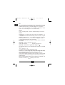
4
Thanks for selecting RVC range of PF controllers for your automatic
capacitor bank.
READ THIS FIRST
About this instruction manual
This Instruction Manual is designed to help you quickly install and
operate the RVC Controller. Before installation and operation of the
RVC Controller, read this notice carefully. Keep it at the disposal of
people in charge of installation, maintenance and operation.
Safety
Installation, maintenance and operation of the PF controller
must be performed by qualified electricians. Disconnect all
power connections before working on the PF controller.
For cleaning, remove the dust with a dry cloth. Do not use abrasives,
solvents or alcohol. Before cleaning please turn off the power supply.
Do not open the PF controller’s housing. There are no user
serviceable parts inside.
The PF controller is connected to a current transformer. Do not
unplug the current transformer connections before making sure it is
short-circuited or connected to another parallel load of sufficiently
low impedance. Failure to do so can create dangerous over
voltages.
Do not use this product for any other purpose than its original aim.
All cables connected to the PF controller must conform to the local
regulations. They should be able to withstand at least 60°C ambient
temperature. External disconnection devices (e.g. a switch) and
external overcurrent protection devices (e.g. fuses) must be
provided for the protection of the PF controller (refer to # 6, F1 and
F2) and for the protection of the capacitor bank (refer to # 6, F3, F4
and F5). These devices must be installed in the same cubicle as the
PF controller. The typical protection level of the disconnection
circuits for the PF controller is 6A. For the capacitor bank, the
protection level depends on its rating.
en
RVA Manual TEXT-final.qxd 5/12/2005 16:57 Page 4

5
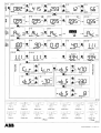
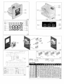
# 1. Front view
1.1. Mounting brackets
1.2. LCD display
1.3. Keypad
# 2. Rear view
2.1. Mounting brackets
2.2. L2 & L3, voltage
connection inputs
2.3. k & I, current connection
inputs
2.4. Steps outputs
# 3. LCD display
3.1. Activated outputs
3.2. Overtemperature indication
3.3. Disconnection indication
3.4. User settable parameters
3.5. Modes
3.6. Demand for switching on or
off capacitor steps
3.7. Inductive PF
3.8. Capacitive PF
3.9. Alarm indication
3.10. Measurement unit
3.11. Refer to § Feature
# 4. Keyp
ad
4.1. Mode button
4.2. - button
4.3. + button
# 5. Mounting
5.1. Slide the controller into the
capacitor bank cubicle.
5.2. Insert the mounting brackets
in the corresponding fixation
holes of the controller. Pull the
mounting brackets backwards.
5.3. Turn the screw into the
mounting brackets and tighten
until the controller is fixed.
en
Electromagnetic compatibility
This PF Controller has been verified for compliance with EU
(European Union) directives for EMC (electromagnetic compatibility)
for operation at 50 Hz and bears the CE marking to this effect.
When an apparatus is used in a system, EU directives may require
that the system be verified for EMC compliance.
The following guidelines are helpful in improving the EMC
performance of a system:
1. Metallic enclosures generally improve EMC performance.
2. Run cables away from apertures in the enclosure.
3. Run cables close to grounded metallic structures.
4. Use multiple ground straps for doors or other panels parts as
required.
5. Avoid common ground impedances.
FIGURES (refer to doc n° 2GCS201086A0050 1/2)
RVA Manual TEXT-final.qxd 5/12/2005 16:57 Page 5

6
SWITCHING STRATEGY
Reactive power requirement is calculated based on average reactive
load during a switching delay time (40 sec. recommended).
RVC decides on the number of steps based on above and switches
on the biggest step first to avoid intermediate switching. During this
switching sequence, a fixed 12-second delay time between each
step is introduced in order to avoid transient problems and to fulfill
EMC requirements. The default switching is circular (# 8.) which
increases lifetime of capacitors/contactors.
MODES
AUTO mode (default)
RVC decides on the number of steps required to reach the target PF
based on user setting (target PF, C/k, ...)
Display of cos ϕ, Vrms, Irms, THDV, THDI. (refer to 10.1)
MAN mode
This mode allows the user to control the power factor manually.
Display of cos ϕ, manual switching of steps. (refer to 10.2.)
en
# 6. Wiring diagram
k, I: leads of the current
transformer
L2, L3: 2 of the 3 phases
M1, M2: leads of the normally
open alarm contact
A: output relay common source
1-12: outputs
# 7. Leads connection
7.1. Push the lever of the
connector backwards with a
screwdriver.
7.2. Insert the wire in the
corresponding connection hole
while keeping the pressure on
the lever.
7.3. Release the screwdriver.
7.4. The wire is properly
connected.
If the connections (CT and
voltage) are done properly, the
RVC will display the PF
measurement screen, in the
Auto mode (refer to # 10.)
Note
: wire size 2.5 mm²
RVA Manual TEXT-final.qxd 5/12/2005 16:57 Page 6

7
AUTO SET mode
Automatic setting of PHASE, C/k, DELAY, STEPS of outputs 1, 2,
3, ... RVC makes the commissioning easy with its AUTO SET mode.
The user only needs to set the desired PF (default factory setting is
1.0) by going to MAN SET mode. This process may take several
minutes to complete. Please refer to 10.3.
Note
: the default time delay is set at 40 sec. If a different delay time
is needed, please do it before starting the AUTO SET procedure.
MAN SET mode
Manual setting of COS ϕ, PHASE, C/k, DELAY, STEPS of outputs 1,
2, 3, ..., Vrms Max, Vrms Min, THDV Max.
Please refer to § Programmable parameters and to 10.4.
Apart from these parameters, RVC has some special features like
target PF in regenerative mode, linear or circular switching mode,
overvoltage and undervoltage threshold limit. (refer to 10.4.)
Note
: any parameter set automatically by the controller can later be
overwritten by the user by using MAN SET mode.
PROGRAMMABLE PARAMETERS
Following are the user programmable parameters with acceptable
values indicated.
COS
ϕϕ
The controller has to reach the target cos ϕ by switching steps.
0.7 ind cos phi 0.7 cap.
PHASE
Used to correct the phase shift due to all possible connections of CT
and voltage circuit (refer to # 11.)
en
RVA Manual TEXT-final.qxd 5/12/2005 16:57 Page 7

C/k
It is the sensitivity of the controller which is set to about 2/3 of the
current of the smallest switched step. C/k is related to the power of
smallest step (Q in kvar), V (nominal voltage in V), k (CT ratio).
0.01 c/k 3.00 (refer to # 9. C/k table for a 3-phase / 400V
system, or use formula given in # 9. for other cases).
DELAY
1 sec switching delay 999 sec. Default setting is 40 seconds.
STEPS
There are max. 12 outputs, each can be set from 0 (disabled), 1...9,
or F (fixed).
‘1’ represents the smallest switched step (refer to c/k ratio). A typical
sequence could be 1:1:2:4... for a 200 kvar bank with 25 kvar as
smallest (represented by ‘1’) and 100 kvar as biggest (‘4’) steps.
‘0’ means that the output is never connected.
‘F’ means that the output is always connected unless a protection
event arises.
FEATURE 1: Linear / circular (refer to # 8.)
Linear: last in first out Circular: first in first out
FEATURE 2: Generative / regenerative target cos
ϕϕ
An alternative target cos ϕ is activated when power flow is reversed
(P < 0).
- 0.7 cos phi - 1.0.
The negative sign indicates regenerative mode.
Protection 1 & 2: Overvoltage (Max Vrms)/undervoltage (Min Vrms)
User settable parameter for protection of capacitor bank.
Recommended values: 0.9 Vnom < Vmin ; Vmax < 1.1 Vnom.
If the system voltage exceeds this limit, all steps are disconnected
one by one. In case of undervoltage, the disconnection is faster (< 1
network period).
Below certain specified voltage, these protections are disabled. This
condition is shown by a “ “ display on the screen.
8
en
RVA Manual TEXT-final.qxd 5/12/2005 16:57 Page 8

Protection 3: Over THDV (Max THDV)
If the THDV exceeds this over THDV limit set by the user, all steps
are disconnected. The reset delay time (default 40 sec) is
automatically doubled each time this event takes place.
Below certain specified THD level, this protection is disabled. This
condition is shown by a “ “ display on the screen.
ALARM AND PROTECTION
RVC controller has a Normally Open (NO) type of alarm contact.
This contact activates (OPEN) when the following situation arise:
9
Reset blinking closed disconnected
(40s)
Alarm ON open all connected
cos
ϕϕ
since more than
6 min.
Over- ON blinking ON open disconnected when
temperature T internal > 85°C
Over- ON blinking ON open disconnected
voltage
Under- ON blinking ON open fast disconnection
voltage <1 network period
Over ON blinking ON open disconnected
THDV
Alarm
relay
en
RVA Manual TEXT-final.qxd 5/12/2005 16:57 Page 9

10
en
Fault
The controller does not switch
on or off steps although there is
a considerable variable inductive
load.
The controller does not seem to
activate any steps.
One of the arrow indicators
flashes.
The preset power factor is not
achieved.
All capacitors are switched on
although the required reactive
power is relatively low.
The controller is connected but
does not work (nothing on
display).
The AUTO SET procedure stops
and the controller displays an
error message “FXX”.
All capacitors are switched off
and the alarm icon is on for more
than 40 sec.
Solution
• Check that the controller is in
automatic Mode.
• Check setting of phase shift
and C/k.
• Check that the CT short-circuit
bridge is removed.
Wait for the delay time between
switching and/or the power
outage delay time.
Normal situation when the actual
inductive current varies around
the set sensitivity (C/k).
At low or no load, a low power
factor can correspond to a very
small inductive current. The
corresponding capacitor steps
are too large for compensation.
If the average cos ϕ over a
period of time is too low, the
preset cos ϕ may be increased.
Check settings of phase and C/k
values.
Check the voltage protection
settings, fuses and voltage
supply.
Please identify the meaning of
the error message (see table on
next page) and act accordingly.
Check the network voltage and
Vmax / Vmin / THDV max
protection parameters.
TROUBLESHOOTING
RVA Manual TEXT-final.qxd 5/12/2005 16:57 Page 10

11
ERROR MESSAGES
Description Recommended action
F1 Current too small. Check that the CT short-circuit is
removed and re-start AUTO SET.
F2 Phase not found Re-start AUTO SET procedure
after 10 trials. under more stable conditions.
Load is varying too quickly.
F3 Phase error: Check connections,
closest value is 0°. capacitors and fuses.
The controller could not find
a known configuration.
F4 ---closest value is 30°.--- ------
F5 ---closest value is 60°.--- ------
F6 ---closest value is 90°.--- ------
F7 ---closest value is 120°.--- ------
F8 ---closest value is 150°.--- ------
F9 ---closest value is 180°.--- ------
F10 ---closest value is 210°.--- ------
F11 ---closest value is 240°.--- ------
F12 ---closest value is 270°.--- ------
F13 ---closest value is 300°.--- ------
F14 ---closest value is 330°.--- ------
F15 C/k not found after 10 trials. Re-start AUTO SET procedure
The load is varying too under more stable conditions.
quickly.
F16 C/k too small (< 0.01). Adapt the step size or the CT
Step size too small ratio.
or CT too big.
F17 C/k too high (> 3.00). Adapt the step size or the CT
Step size too big ratio.
or CT too small.
F18 Sequence not found after Re-start AUTO SET procedure
10 trials. The load is varying under more stable conditions.
too quickly.
F19 Unknown sequence. The Check connections,
controller could not find a capacitors and fuses.
known sequence.
en
RVA Manual TEXT-final.qxd 5/12/2005 16:57 Page 11

12
en
Measuring system:
Micro-processor system for
balanced three-phase networks
or single-phase networks.
Operating voltage:
100V to 440V.
Voltage tolerance:
+/- 10% on indicated operating
voltages.
Frequency range:
50 or 60 Hz +/- 5% (automatic
adjustments to network
frequency).
Measuring circuit terminals
(L2, L3 and k, l):
CAT. III rated.
Current input:
1A or 5A (RMS).
Current input impedance:
<0.1 Ohm (recommended CT
class 1.0, 10 VA min).
Consumption of the
controller:
8 VA max.
Output contact rating:
•
Max. continuous current: 1.5A.
•
Max. peak current: 5A.
•
Max. voltage: 440 Vac.
•
Terminal A is rated for a
continuous current of 16A.
Alarm contact:
•
Normally open contact.
•
Max. continuous current: 5A.
•
Rated/max. breaking voltage:
250Vac/440Vac.
Power factor setting:
From 0.7 inductive to 0.7
capacitive.
Starting current setting (C/k):
•
0.01 to 3A .
•
automatic measurement of C/k.
Number of outputs:
RVC 3: 3 RVC 10: 10
RVC 6: 6 RVC 12: 12
RVC 8: 8
Switching time between steps:
programmable from 1s to 999s
(independent of reactive load).
Switching sequences:
User defined.
TESTING
MAN mode: add one step, the power factor (cos ϕ) should improve
indicated by a value which is bigger in the inductive range as before.
AUTO mode: after setting the target cos ϕ, RVC should reach this
value after having switched steps.
TECHNICAL SPECIFICATIONS
RVA Manual TEXT-final.qxd 5/12/2005 16:57 Page 12

13
Mode of switching:
Integral, direct, circular or linear.
Saving-function:
All programmed parameters and
modes are saved in a non-
volatile memory.
Power outage release:
Quick automatic disconnection in
less than 20ms (50Hz) in case of
power outage or voltage drop.
Power outage reset delay time:
40s.
Overvoltage and undervoltage
protection.
Autoadaptation to the phase-
rotation of the network and
the CT-terminals.
Not affected by the harmonics.
Working with generative and
regenerative loads.
LCD contrast automatically
compensated with
temperature.
Operating temperature:
-10°C to 60°C.
Storage temperature:
-30°C to 85°C.
Mounting position:
Vertical panel mounting.
Dimensions:
144x144x80 mm (hxwxd).
Weight:
0.4 kg (unpacked).
Connector:
Spring clamp terminal block,
max 2.5 mm².
Front plate protection:
IP 40.
Relative humidity:
Maximum 95%; non-condensing.
CE Marked.
en
RVA Manual TEXT-final.qxd 5/12/2005 16:57 Page 13

54
de
Danke, das Sie einen RVC-Blindleistungsregler für Ihre automatische
Kondensatorbank ausgewählt haben.
BITTE ZUERST LESEN
Zu dieser Anleitung
Diese Anleitung wurde so gestaltet, dass Sie Ihnen hilft, den RVC
Blindleistungsregler schnell zu installieren und in Betrieb zu nehmen.
Vor der Installation und der Inbetriebnahme des RVC Reglers lesen Sie
bitte sorgfältig diese Anleitung. Halten Sie die Anleitung für alle mit
der Installation, der Wartung und dem Betrieb betrauten Personen zur
Einsicht bereit.
Sicherheit
Installation, Wartung und Betrieb des RVC Blindleistungsreglers
dürfen nur durch entsprechend qualifizierte Elektriker
vorgenommen werden. Schalten Sie den Regler spannungsfrei bevor
Sie an ihm arbeiten. Reinigen Sie den Regler indem Sie
Staubablagerungen mit einem trockenen Tuch abwischen. Benutzen
Sie weder scharfe Reinigungsmittel, noch Alkohol oder Lösungsmittel.
Schalten Sie den Regler vor der Reinigung spannungsfrei.
Öffnen Sie nicht das Gehäuse des Blindleistungsreglers. Innerhalb
des Gehäuses befinden sich keine wartungsfähigen Teile.
Der Blindleistungsregler ist an einen Stromwandler angeschlossen.
Trennen Sie die Verbindungen des Stromwandlers nicht ab, solange
Sie nicht sichergestellt haben, dass dieser kurzgeschlossen ist oder
an eine andere parallele Last mit ausreichend geringem
Scheinwiderstand angeschlossen ist. Das Nichtbeachten dieses
Hinweises kann gefährliche Überspannungen zur Folge haben.
Verwenden Sie dieses Produkt für keinen anderen als den ursprünglich
vorgesehenen Einsatz. Alle am Blindleistungsregler angeschlossenen
Leiter müssen den örtlichen Vorschriften entsprechen. Sie sollten
mindestens für eine Umgebungstemperatur von 60°C geeignet sein.
Externe Trennvorrichtungen (z. B. Schalter) und
Überstromschutzeinrichtungen (z. B. Sicherungen) müssen zum Schutz
des Reglers (siehe # 6, F1 und F2) sowie zum Schutz der
Kondensatorbank (siehe # 6, F3, F4 und F5) eingesetzt werden. Diese
Schutzeinrichtungen müssen im selben Schaltschrank eingebaut
werden, wie der Regler. Die übliche Absicherung des Reglers ist 6 A,
die Absicherung der Kondensatorbank ist abhängig von der
Stufenleistung.
RVA Manual TEXT-final.qxd 5/12/2005 16:57 Page 54

55
de
# 1. Frontansicht
1.1. Montageklammern
1.2. LCD-Display
1.3. Tastenblock
# 2. Rückansicht
2.1. Montageklammern
2.2. L2 & L3,
Eingangsanschlüsse f. Spannung
2.3. k & I, Eingangsanschlüsse
f. Strom
2.4. Ausgänge f. Kondensatorstufen
# 3. LCD-Display
3.1. Aktivierte Ausgänge
3.2. Übertemperaturanzeige
3.3. Schutzabschaltung
3.4. Vorgabewerte des Benutzers
3.5. Betriebsarten
3.6. Anforderung zum Ein- oder
Ausschalten von
Kondensatorstufen
3.7. Induktiver Leistungsfaktor
3.8. Kapazitiver Leistungsfaktor
3.9. Alarmanzeige
3.10. Einheit der Messgrösse
3.11. Siehe Abschnitt “Feature”
# 4. T
astenblock
4.1. Taste MODE (Betriebsart)
4.2. Taste -
4.3. Taste +
# 5. Mont
age
5.1. Schieben Sie den Regler in
den Reglerausschnitt.
5.2. Setzen Sie die
Montageklammern in die
entsprechenden
Befestigungsöffnungen des
Reglers ein. Ziehen Sie die
Montageklammern nach hinten.
Elektromagnetische Verträglichkeit
Dieser Blindleistungsregler wurde auf seine Konformität mit den EU-
Richtlinien für Elektromagnetische Verträglichkeit (EMV) für den Betrieb
mit 50 Hz geprüft und entsprechend mit dem CE-Zeichen versehen.
Wenn eine Einrichtung innerhalb eines Systems eingesetzt wird, so
können EU-Richtlinien möglicherweise erfordern, dass das System
auf seine Konformität hinsichtlich EMV zu prüfen ist.
Durch Berücksichtigung folgender Richtlinien kann die EMV-
Leistungsfähigkeit eines Systems verbessert werden:
1. Metallgehäuse verbessern generell die EMV-Leistungsfähigkeit.
2. Führen Sie Kabel abseits von Öffnungen im Gehäuse.
3. Führen Sie Kabel nahe zu geerdeten Metallstrukturen.
4. Setzen Sie je nach Bedarf mehrfache Erdungslaschen für Türen
und andere Gehäuseteile ein.
5. Vermeiden Sie Erdübergangswiderstände.
ABBILDUNGEN (Siehe Dokument n° 2GCS201086A0050 1/2)
RVA Manual TEXT-final.qxd 5/12/2005 16:57 Page 55

56
de
SCHALTSTRATEGIE
Die notwendige Kompensationsblindleistung wird aus der
durchschnittlichen Last während der Schaltverzögerungszeit
(empfohlen: 40 s) berechnet. Der RVC berechnet die Anzahl benötigter
Stufen und schaltet die grösste Stufe zuerst, um unnötige
Zwischenschritte zu vermeiden. Das Einschalten erfolgt mit einer
festen Verzögerungszeit von 12 Sekunden zwischen den Stufen, um
transiente Probleme zu vermeiden und EMV-Anforderungen zu erfüllen.
Kreisschaltung (siehe # 8.) ist voreingestellt, um die Lebensdauer der
Kondensatoren/Schütze nicht unnötig zu verkürzen.
BETRIEBSARTEN
AUTO mode (Standard)
Der RVC berechnet die Anzahl benötigter Stufen, um den gewünschten
Leistungsfaktor gemäss den vorgegebenen Anlagenparametern zu
erreichen (target PF, C/k, ...)
Anzeige von cos ϕ, Vrms, Irms, THDV, THDI. (siehe 10.1).
5.3. Drehen Sie die Schraube in
die Montageklammern und ziehen
Sie die Verbindung so weit an,
dass der Regler fest montiert ist.
# 6. V
erdrahtungsplan
k, I: Zuleitungen des
Stromwandlers (CT)
L2, L3: 2 der 3 Phasen (nicht von
Stromwandler überwacht)
M1, M2: Anschlussklemmen des
Schliesser-Alarmkontaktes (NO)
A: Stromversorgung Ausgangsrelais
1-12: Ausgänge
# 7. Anschluß der Zuleitungen
7.1. Drücken Sie den Hebel des
Steckverbinders mit einem
Schraubendreher nach hinten.
7.2. Setzen Sie den
Anschlußdraht in die
entsprechende
Verbindungsöffnung ein,
während Sie den Druck auf den
Hebel beibehalten.
7.3. Entfernen Sie den
Schraubendreher.
7.4. Der Anschlußdraht ist korrekt
verbunden.
Bei korrekter Verdrahtung
(Wandler und Spannung) zeigt der
Regler im “AUTO”-Modus den
Leistungsfaktor an (siehe # 10.)
Achtung
: Anschlussquerschnitt
2.5 mm²
RVA Manual TEXT-final.qxd 5/12/2005 16:57 Page 56

57
de
MAN mode
In dieser Betriebsart kann der Nutzer den Leistungsfaktor manuell
beeinflussen.
Anzeige von cos ϕ, manuelles Schalten von Stufen (siehe 10.2.).
AUTO SET mode
Selbstprogrammierung von PHASE, C/k, DELAY, STEPS der Ausgänge
1, 2, 3, ... Die Inbetriebsetzung des RVC wird durch den AUTO SET
mode sehr vereinfacht.
Der Nutzer muss nur den gewünschten Soll-Leistungsfaktor eingeben
(Werkseinstellung: 1,0) während er durch den MAN SET mode geht.
Die Selbstprogrammierung kann einige Minuten dauern (siehe 10.3).
Hinweis
: Als Verzögerungszeit sind 40 s voreingestellt. Falls eine
andere Zeit gewünscht wird ändern Sie diese bitte vor dem AUTO
SET.
MAN SET mode
Manuelle Eingabe von COS ϕ, PHASE, C/k, DELAY, STEPS der
Ausgänge 1, 2, 3, ..., Vrms Max, Vrms Min, THDV Max.
Siehe Abschnitte programmierbare Parameter und 10.4.
Neben diesen Parametern hat der RVC einige spezielle Funktionen,
wie Leistungsfaktor bei generatorischer Last, lineare oder
Kreisschaltung Über- und Unterspannungsgrenzwerte (siehe 10.4).
Hinweis
: Jeder bei der Selbstprogrammierung gefundene Wert kann
später im MAN SET mode geändert werden.
PROGRAMMIERBARE PARAMETER
Im folgenden sind die vom Nutzer programmierbaren Parameter und
Ihre zulässigen Werte angegeben.
COS
ϕϕ
Der Regler muss den Soll-cos ϕ durch Schalten von Stufen erreichen.
0.7 ind cos phi 0.7 cap.
PHASE
Wird benutzt, um mögliche Phasendrehungen durch die möglichen
Kombinationen von Wandlereinbau und Spannungsanschluss zu
korrigieren (siehe # 11.).
RVA Manual TEXT-final.qxd 5/12/2005 16:57 Page 57

58
de
C/k
Dies ist die Ansprechempfindlichkeit des Reglers, die auf 2/3 des
Sekundärstromes der kleinsten Stufe gesetzt wird. C/k hängt ab von
der Leistung der kleinsten Stufe (Q in kvar), der Spannung
(Nennspannung in V) und dem Wandlerübersetzungsverhältnis k.
0.01 c/k 3.00 (siehe # 9. C/k Tabelle für ein Dreiphasensystem
400V, oder in anderen Fällen mit der Formel in # 9.).
DELAY
1 Sek Verzögerungszeit 999 Sek. Voreingestellt sind 40 Sekunden.
STEPS
Der Regler hat max. 12 Ausgänge, jeder kann auf 0 (deaktiviert), 1 …
9 oder F (Feststufe) gesetzt werden.
‘1’ entspricht der kleinsten Schaltstufe (Referenz für C/k-Wert). Eine
typische Schaltfolge kann 1:1:2:4… for a 200 kvar bank with 25 kvar
als kleinste (‘1’), 50 kvar (‚2’) und 100 kvar als grösste Stufen (‘4’).
‘0’ bedeutet, dass der Ausgang nie eingeschaltet wird (nicht belegt,
defekt).
‘F’ bedeutet, dass der Ausgang immer eingeschaltet ist, falls keine
Schutzabschaltung erfolgt.
FEATURE 1: Linear / circular (siehe # 8.)
Linear: Zuletzt eingeschaltet / zuerst ausgeschaltet
Circular: Kreisschaltung, zuerst eingeschaltet / zuerst ausgeschaltet
FEATURE 2: Erzeuger- / Verbraucher- Soll-cos
ϕϕ
Ein alternativer Soll-cos ϕ wird aktiviert, wenn sich die
Wirkleistungsrichtung umkehrt (P < 0).
- 0.7 cos phi - 1.0.
Das negative Vorzeichen weist auf die Wirkleistungsrückspeisung hin.
Schutz 1 & 2: Überspannung (Max Vrms) / Unterspannung (Min Vrms)
Vom Nutzer vorgebbarer Wert für den Schutz der Kondensatorbank.
Empfohlene Werte: 0.9 Vnom < Vmin ; Vmax < 1.1 Vnom.
Falls die Netzspannung über dem Grenzwert liegt werden alle Stufen
nacheinander ausgeschaltet. Bei Unterspannung erfolgt die Abschaltung
schneller (< 1 Netzperiode).
RVA Manual TEXT-final.qxd 5/12/2005 16:57 Page 58

59
de
Unterhalb eines bestimmten Werte ist diese Funktion deaktiviert. Dieser
Zustand wird mit “ “ im Display angezeigt.
Schutz 3: Spannungsverzerrung THDV zu gross (Max THDV)
Falls der THDV den vom Nutzer vorgegebenen THDV-Grenzwert
überschreitet werden alle Stufen abgeschaltet. Die Reset-
Verzögerungszeit (Voreinstellung 40 s) wird jedes Mal verdoppelt,
wenn dies auftritt.
Unterhalb eines bestimmten THD-Wertes ist diese Funktion deaktiviert.
Dieser Zustand wird mit “ “ im Display angezeigt.
ALARM UND SCHUTZ
Der RVC-Regler hat einen Schliesser-Alarmkontakt (NO).
Der Kontakt wird aktiviert (geöffnet), wenn:
Startzeit blinkt ge- ausgeschaltet
(40s) schlossen
Alarm EIN offen alle seit mehr als
cos
ϕϕ
6 min
zugeschaltet
Über- EIN blinkt EIN offen Ausgeschaltet, falls
temperatur T intern > 85°C
Über- EIN blinkt EIN offen ausgeschaltet
spannung
Unter- EIN blinkt EIN offen schnelle Abschaltung
spannung <1 Netzperiode
THDV EIN blinkt EIN offen ausgeschaltet
zu gross
Alarm-
Kontakt
RVA Manual TEXT-final.qxd 5/12/2005 16:57 Page 59

60
de
Störung
Der Regler schaltet Stufen nicht
ein oder aus, obwohl eine
bedeutende variable, induktive
Last vorliegt.
Der Regler scheint keine Stufe
zu aktivieren.
Eine der Anzeigen blinkt.
Der voreingestellte Leistungsfaktor
wird nicht erreicht.
Alle Kondensatoren sind
eingeschaltet, obwohl die
benötigte Blindleistung relativ
niedrig ist.
Der Regler ist angeschlossen,
arbeitet jedoch nicht (keinerlei
Anzeigen am Display).
Lösung
• Überprüfen Sie, ob der Regler
sich in der Betriebsart AUTO
(Automatik) befindet.
• Überprüfen Sie die Einstellung
der Phasenverschiebung und
des Wertes für C/k.
• Überprüfen Sie, ob die
Kurzschlußbrücke am
Stromwandler entfernt wurde.
Warten Sie die Verzögerungszeit
zwischen den Schaltvorgängen
und/oder die Verzögerungszeit
bei Stromausfall ab.
Normale Situation, wenn der
tatsächliche induktive Strom im
Bereich der eingestellten
Empfindlichkeit (C/k) schwankt.
Bei geringer oder keiner Last
kann ein niedriger
Leistungsfaktor einem sehr
geringen induktiven Strom
entsprechen.
Die entsprechenden
Kondensatorstufen sind für eine
Kompensation zu groß. Falls der
Mittelwert des Leistungsfaktors
cos ϕ über eine bestimmte
Zeitdauer zu klein ist, sollte der
voreingestellte Leistungsfaktor
cos ϕ möglicherweise erhöht
werden.
Überprüfen Sie die Einstellung
der Werte für Phase und C/k.
Prüfen Sie die Einstellwerte für
Über-/Unterspannungsschutz,
die Sicherungen und die
Versorgungsspannung.
STÖRUNGSBEHEBUNG
RVA Manual TEXT-final.qxd 5/12/2005 16:57 Page 60
Seite wird geladen ...
Seite wird geladen ...
Seite wird geladen ...
Seite wird geladen ...
Seite wird geladen ...
Seite wird geladen ...
-
 1
1
-
 2
2
-
 3
3
-
 4
4
-
 5
5
-
 6
6
-
 7
7
-
 8
8
-
 9
9
-
 10
10
-
 11
11
-
 12
12
-
 13
13
-
 14
14
-
 15
15
-
 16
16
-
 17
17
-
 18
18
-
 19
19
-
 20
20
-
 21
21
-
 22
22
-
 23
23
-
 24
24
-
 25
25
-
 26
26


ABB RVC Installation And Operating Instructions Manual
- Typ
- Installation And Operating Instructions Manual
in anderen Sprachen
- English: ABB RVC
Andere Dokumente
-
Candy GO F 166/L Datenblatt
-
Exquisit KS 16-4 RV A++ Datenblatt
-
Yamaha AST-A10 Bedienungsanleitung
-
-
Mettler Toledo Rainin SmartStand Benutzerhandbuch
-
Behringer MA6480A Schnellstartanleitung
-
Behringer EUROCOM MA6000M Schnellstartanleitung
-
-
-
Caraudio Systems V4-NBT Installationsanleitung