ITALIANOPOLSKIESPAÑOL
FRANCAISDEUTSCHENGLISH
13
MICROPHONE STATION STATUS DISPLAY
To view the status information of individual microphone stations, adjust the individual volume and in order to make changes in the micro-
phone station menu, press the switch corresponding to the desired microphone station (in this example RX1 = MIC 1). To adjust the volume,
use the pressure rotary encoder PUSH TO ENTER (rotate right = increase volume, rotate left = lower volume). In order to make changes in
the microphone station menu, press on the pressure rotary encoder.
Switch RX 1 - RX 4
Battery status
Frequency channel and frequency group
- Active antenna and radio signal level
- Audio signal level with Peak display (PK)
- Volume adjustment
Microphone station with priority
Mute function activated (mute)
Microphone station number and radio frequency
IR SYNC RUN
To synchronise the microphone station with the radio channel set in the receiver, bring the infrared port of the microphone station in direct visual
contact with the infrared port of the receiver (distance approx. 10 cm) and turn on the microphone station. Press the switch corresponding to
the desired microphone station (in this example RX 1 = MIC 1) and then press the pressure rotary encoder
PUSH TO ENTER. Now select the IR SYNC RUN menu item by rotating the encoder (light background) and press the encoder once more to
launch the synchronisation process. After a few seconds, the process is completed and the display of the microphone station switches for a
short time to “IR SYNC”, confirming successful synchronisation. When daisy-chaining the receivers, the microphone station numbers are
assigned automatically (Master = MIC 1 - 4, Slave 1 = MIC 5 - 8, Slave 2 = MIC 9 - 12, Slave 3 = MIC 13 - 16, Slave 4 = MIC 17 - 20). The
microphone station numbers are automatically transmitted to the microphone station during the synchronisation process and are shown on the
display. To cancel the operation, press the encoder. To return to the main display, select EXIT now by rotating the encoder (light background)
and confirm by pressing the encoder. Then press the switch corresponding to the desired microphone station (RX 1 - 4). After approximately 10
seconds of inactivity, the display will automatically return to the main screen.
FREQ AUTO RUN
Automatic frequency search (frequency scan) to determine an interference-free radio frequency in the current environment and to allow for
optimal reception. For this purpose, leave the corresponding transmitter off, but other radio systems turned on, if necessary. To start the
automatic frequency search, press the switch corresponding to the desired microphone station (in this example RX 1 = MIC 1) and press
the pressure rotary encoder PUSH TO ENTER. Now select the FREQ AUTO RUN menu item by rotating the encoder (light background). To
confirm the operation, press the encoder. Progress is now indicated on the display by an animation and the scanning process is completed
after a few seconds (to cancel, press the encoder). The resulting frequency is automatically enabled and, as in “IR SYNC RUN”, you can now
switch on the transmitter and synchronise it with the receiver. To return to the main display, select EXIT now by rotating the encoder (light
background) and confirm by pressing the encoder. Then press the switch corresponding to the desired microphone station (RX 1 - 4). After
approximately 10 seconds of inactivity, the display will automatically return to the main screen.
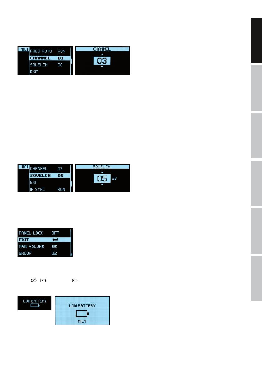
CHANNEL
Menu item to manually adjust the frequency channel. Press the switch corresponding to the desired microphone station (in this example RX
1 = MIC 1) and then press the pressure rotary encoder
PUSH TO ENTER. Now select the CHANNEL menu item by rotating the encoder (light background) and press the encoder 2x to adjust the
frequency channel as desired by rotating the encoder. Confirm the entry by pressing the encoder. If you press the encoder only 1x, you can
exit this menu item without changes by rotating the encoder and selecting the arrow symbol (light background) and confirm by pressing the
encoder. To return to the main display, select EXIT now by rotating the encoder (light background) and confirm by pressing the encoder. Then
press the switch corresponding to the desired microphone station (RX 1 - 4). After approximately 10 seconds of inactivity, the display will
automatically return to the main screen. Synchronise the microphone station with the radio frequency set in the receiver as described in IR
SYNC RUN.
Note: Only frequency channels which are not already used by another microphone station can be set.
SQUELCH
The squelch control prevents unwanted background noise when the transmitter is turned off. In addition, sudden background noises are suppressed
when the signal transmitted from the transmitter to the receiver is not strong enough (for instance because of excessive distance) Set the squelch
control (with the transmitter switched off) to the lowest setting, which still effectively suppresses background noises. With an increased squelch
level and in unfavourable conditions, the transmission range may decrease. Press the switch corresponding to the desired microphone station (in
this example RX 1 = MIC 1) and then press the pressure rotary encoder
PUSH TO ENTER. Now select the SQUELCH menu item by rotating the encoder (light background) and press the encoder 2x to adjust the squelch
level as desired (00 - 50 dB) by rotating the encoder. Confirm the entry by pressing the encoder. If you press the encoder only 1x, you can exit this
menu item without changes by rotating the encoder and selecting the arrow symbol (light background) and confirm by pressing the encoder. To
return to the main display, select EXIT now by rotating the encoder (light background) and confirm by pressing the encoder. Then press the switch
corresponding to the desired microphone station (RX 1 - 4). After approximately 10 seconds of inactivity, the display will automatically return to the
main screen.
EXIT (in the microphone station menu)
To return to the main display, select EXIT on the encoder by rotating the encoder (light background) and confirm by pressing the encoder.
Then press the switch corresponding to the desired microphone station (RX 1 - 4). After approximately 10 seconds of inactivity, the display
will automatically return to the main screen.
BATTERY STATUS
The battery status of the microphone station will appear in the display and is constantly updated. When the batteries are fully charged, the
symbol
( = approx. 70%, = approx. 30%) will appear. As soon as the charge of the batteries is low, the display on the transmitter
will show “LOW BATTERY” and the display on the receiver “LOW BATTERY” approximately every 4 seconds, and the number of the microphone
station with low batteries will be displayed. Replace the batteries immediately.


